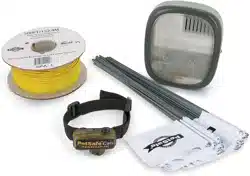
Loading ...
Loading ...
Loading ...
8 www.petsafe.net
Additional Boundary Wire
ExtradirectburialBoundaryWirecanbepurchasedin150m(500ft)
spools at the store where you purchased the kit or through the Customer
Care Centre.
Note: When adding Boundary Wire, it must act as a continuous loop.
The table at right indicates the approximate length of Boundary Wire
needed for a square, Single Loop layout. Length will vary due to the
amount of twisted wire and layout used. Remember that a Double
Loop will require twice as much wire.
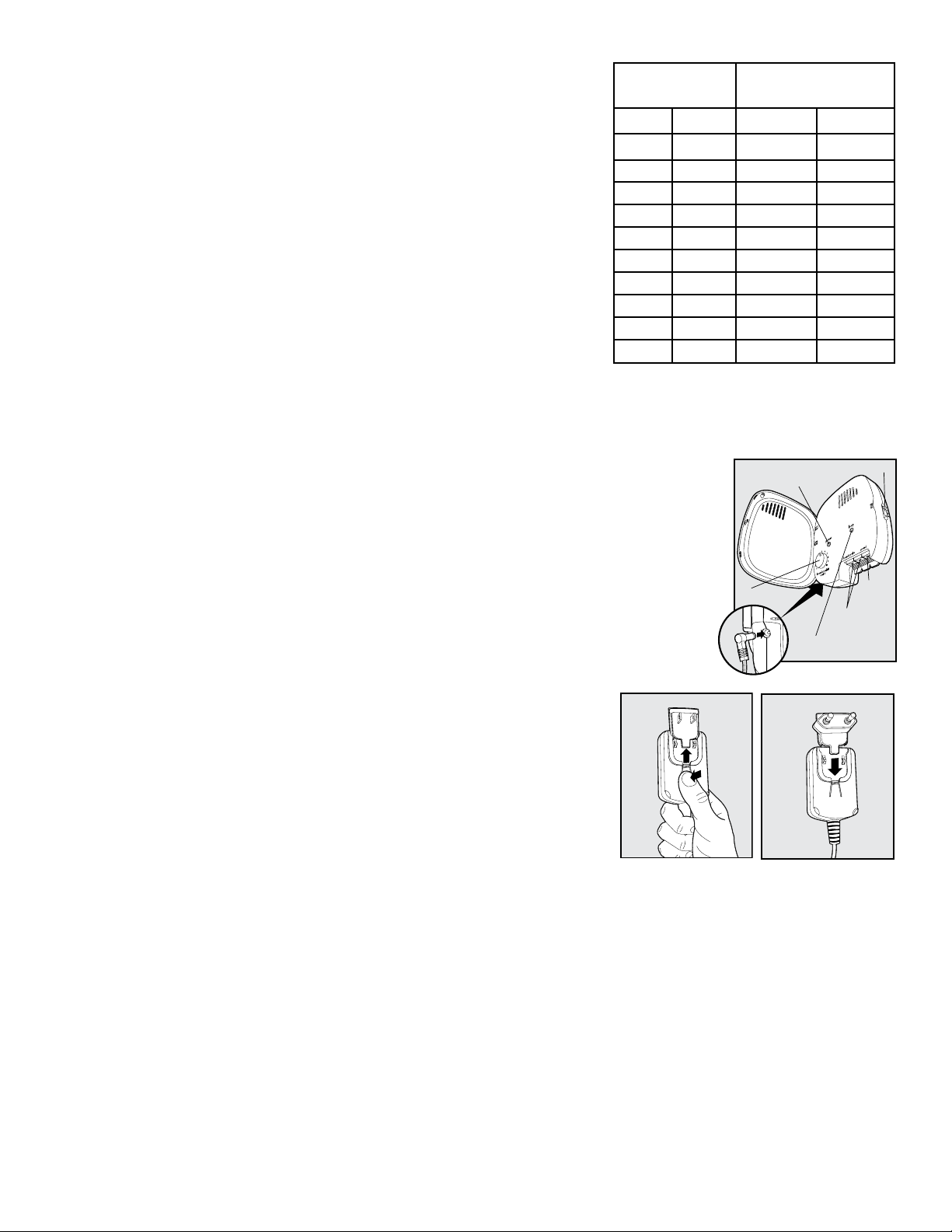
Area to be
enclosed
Approximate wire
length required
Ares Acres Metres Feet
10 1/4 127 415
13 1/3 146 480
20 1/2 180 590
40 1 255 835
80 2 360 1180
200 5 570 1870
400 10 800 2600
600 15 1000 3200
800 20 1100 3700
900 22 1200 4000
__________________________________________________
Connect the Wires to the Fence Transmitter
Boundary Wire
(4A)
1. Run the Boundary Wire to the Fence Transmitter through a window, under a door,
through a crawl space vent, or any other appropriate available access. You can also
drill a hole through your wall.
2.StriptheendsoftheBoundaryWireapproximately1.3cm(
1
/
2
").
3. Insert the Boundary Wires into the Boundary Wire Terminals on the Fence
Transmitter. Make sure wires do not touch each other at the terminals.
4. Turn the Boundary Width Control knob to 10. This will set the Warning Zone at the
maximum width.
5. Plug the Power Adapter into the Power Socket and a working outlet. The Power
Adapter comes with the North American plug installed and additional plugs for the
UKandEurope.Tochangetheplug:
Boundary Control Switch
Ground
Te rminal
Boundary Wire
Te rminals
Loop Indicator Light
Power Light
Power
Socket
Boundary Width
Control
4A
a. Push in the tab on the Power Adapter and remove the plug by
slidingitoffasshown(4B).
b. Slide the proper plug for your electrical outlet onto the Power
Adapterasshown(4C).
6. The Power Light and Loop Indicator Lights should come on. If this
does not happen, see the “Troubleshooting” section.
4B 4C
Step
4
Loading ...
Loading ...
Loading ...