Loading ...
Loading ...
Loading ...
Application Examples
DS O5000 Series Digital Storage Oscilloscope User Manual
53
5. Turn the VOLTS/DIV knobs to display approximately the same amplitude signals on each
channel.
6. Push the DISPLAY button to see the Display menu.
7. Push the Format option button and select
XY.
8. Now the oscilloscope displays a Lissajous pattern to characterize the input and output of the
circuit.
9. Turn the VOLTS/DIV and VERTICAL POSITION knobs to properly scale the waveform
display.
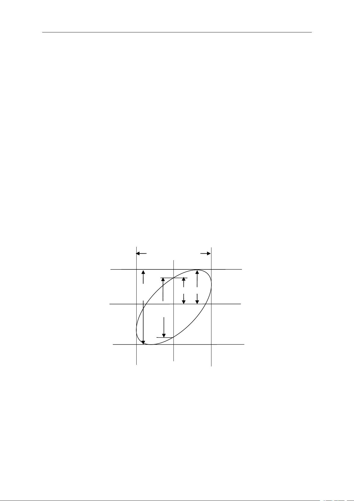
10. Use the Lissajous's oscillographic method to observe and calculate the phase differences
following the formula below.
As sin
sin
sin
sin θ
θ
θ
θ =A/B
=A/B
=A/B
=A/B or
or
or
or C/D
C/D
C/D
C/D , in which θ is the phase difference angle between channels and A , B , C , D
represent what shown in the figure below, you can get the value of the phase difference angle by
the formula: θ
θ
θ
θ =
=
=
= ±
±
±
± arcsin(A/B)
arcsin(A/B)
arcsin(A/B)
arcsin(A/B) or
or
or
or ±
±
±
± arcsin(C/D)
arcsin(C/D)
arcsin(C/D)
arcsin(C/D) .
If the principal axes of the ellipse are in the first and third quadrants, the phase difference angle
should be in the first and fourth quadrants, i.e. within ( 0~ π /2 ) or ( 3 π /2~2 π ). If the principal axes of
the ellipse are in the second and fourth quadrants, the phase difference angle should be in the
second and third quadrants, i.e. within ( π /2~ π ) or ( π -3 π /2 ). See the figure below for better
understanding.
A
B
C
D
Signal H orizontal
C entering
6.6
6.6
6.6
6.6 Example
Example
Example
Example 6:
6:
6:
6: Triggering
Triggering
Triggering
Triggering on
on
on
on Pulse
Pulse
Pulse
Pulse Width
Width
Width
Width
Triggering
Triggering
Triggering
Triggering on
on
on
on a
a
a
a Specific
Specific
Specific
Specific Pulse
Pulse
Pulse
Pulse Width
Width
Width
Width
While testing the pulse width of a signal in a circuit, you may need to verify the pulse width is
consistent with the theoretic value. Or even if the edge triggering shows that your signal has the
same pulse width with the specific signal, you still doubt about the result. Then you can follow the
steps below.
Loading ...
Loading ...
Loading ...