Loading ...
Loading ...
Loading ...
42
31-1000600 Rev. 0
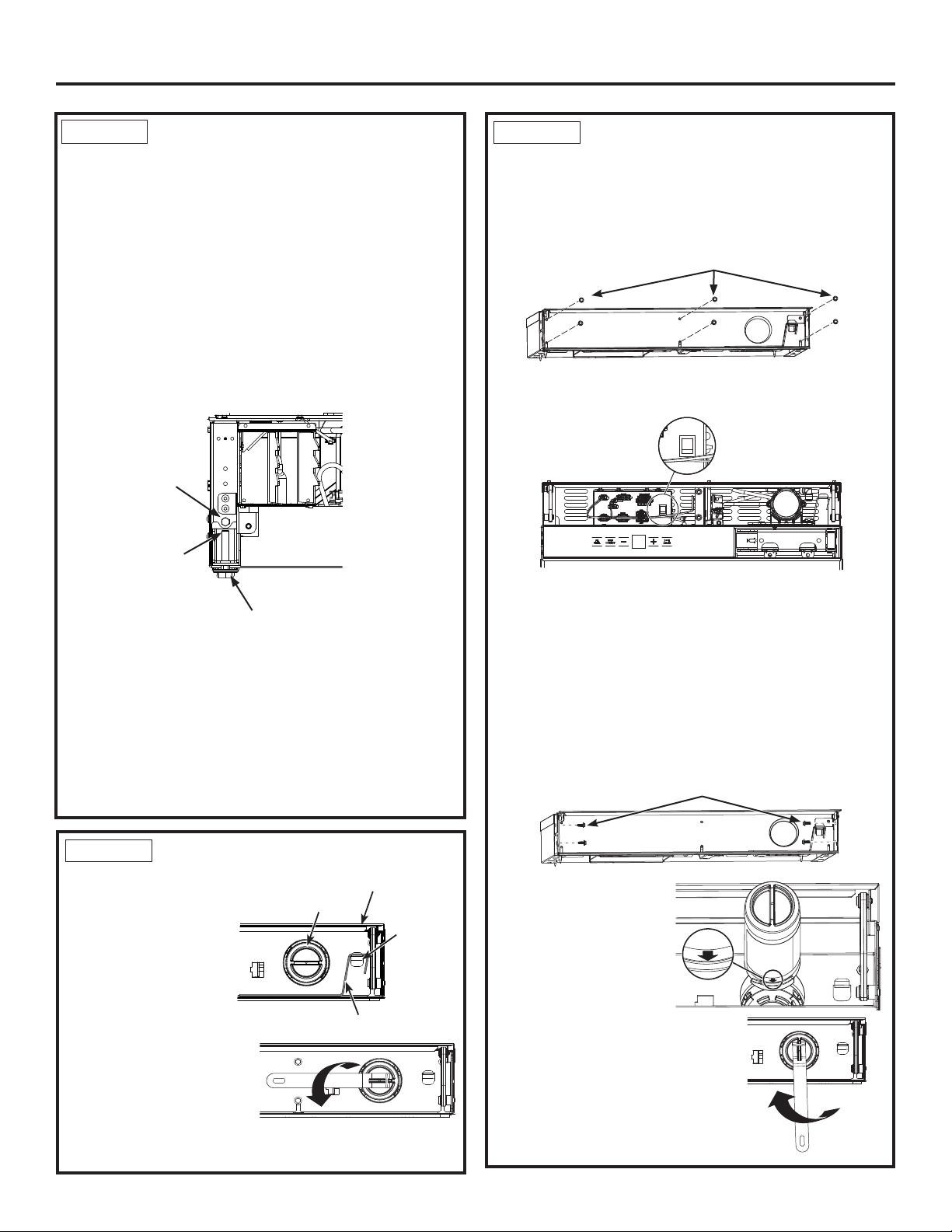
Installation Instructions - Dual Retro-Fit Installation
Ŷ Make sure lights are on inside the unit. If they are not
on, check to make sure the master switch is on by
removing the front enclosure which is secured with
six 1/4” Hex screws.
Ŷ Switch on the master switch if not on. (Master Switch
Wires hidden for clarity.
Ŷ Assemble the enclosure with removed screws.
Ŷ Predrill 1/16” holes is both the sides of the surround
1/2” deep through holes in the enclosure.
Ŷ Secure unit by driving four 1/4” hex screws to both
sides to surrounding cabinetry. NOTE: This step
does NOT replace the anti-tip safety hardware. Refer
to Step 4 Installing Anti-Tip Bracket and Step 7
Inserting/Securing into Cabinet Surround for details
on installing the anti-tip hardware. Repeat for the
second unit.
Ŷ Locate blue arrow on
¿OWHU5RWDWH¿OWHUWR
align arrow as shown.
Ŷ,QVHUW¿OWHULQWRSRVLWLRQ
DQGURWDWHóWXUQ
FORFNZLVHXVH¿OWHU
removal tool if needed).
Ŷ5HWXUQ¿OWHUUHPRYDOWRROWR
mounting hook.
Ŷ Close the compartment door.
STEP 9
FINAL EXTERNAL UNIT
PREPARATION
Ŷ Open the doors to
the units. Locate
¿OWHUDQG¿OWHU
removal tool. Filter
should be as shown.
Ŷ5RWDWH¿OWHUóWXUQ
counterclockwise
XVH¿OWHUUHPRYDO
tool if needed).
Ŷ3XOO¿OWHUWRZDUG\RXWR
remove. NOTE: Water
system will not function
ZLWKRXW¿OWHULQSODFH
STEP 9
FINAL EXTERNAL UNIT
PREPARATION (Cont.)
Master Switch
1/4” Hex Screws
1/4” Hex Screws
Filter Removal Tool
Filter
Mounting
Hook
Compartment Door
STEP 8 LEVEL UNIT
All models have 4-point leveling. The front is supported
by leveling legs; the rear is supported by adjustable
wheels. Both are accessible from the front of the unit.
Ŷ To level the back of the unit, turn the 7/16” hex nut
located above the front leveling legs. Turn clockwise
to raise or counterclockwise to lower the unit.
Ŷ)RUIURQWOHYHOLQJXVHD7ELWDWWKHWRSRIWKH
leveling leg or a 7/16” open-end wrench at the bottom
of the leveling leg.
Ŷ$GMXVWKHLJKWRIXQLWWRPDWFKLQVWDOODWLRQFXWRXW
opening 84”. The unit should be level and plumb with
cabinetry.
NOTICE: The rear leveling wheels and front leveling
legs are limited to a maximum height adjustment of 1”.
If the installation requires more than 84” height, the
installer should elevate the unit on a sheet of plywood
or runners. Cabinetry trim could also be added across
the top of the opening to shorten the opening. If you
attempt to raise the unit more than 1”, you will damage
the front leveling legs and the rear leveling wheels.
T30 bit
adjusts front
leveling legs
7/16” hex nut
adjusts rear
wheels
7/16” open end
wrench adjusts
front leveling legs
Loading ...
Loading ...
Loading ...