Loading ...
Loading ...
Loading ...
07/19/2022Page 36 of 76 TRUE RESIDENTIAL
®
PAGE TITLE
TEC_TM_009 | REV. G | EN
INSTALLATION
JOINING KIT INSTALLATION
Kit Sizes: 60" (1524 mm) / 72" (1828.8 mm) / 78" (1981.2 mm) / 90" (2286 mm)
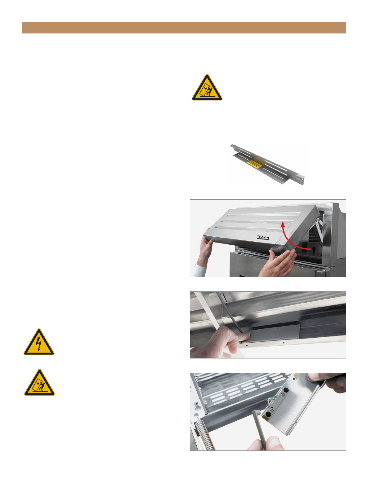
FIG. 1.
Anti-tip bracket. Be sure to install a bracket for each unit.
KIT CONTENTS
• (1) Joining Rainshield Assembly
• (1) Joining Kickplate
• Anti-Sweat Foam End Panels*
• Joining Bracket*
• 1/4-20 x 1" Hex Head Screws*
• 1/4" Split Lock Washers*
*Quantities vary by kit size.
REQUIRED TOOLS
Required tools include (but may not be limited to) the
following:
• Phillips Bit Driver or Screwdriver
• 7/16" Socket Wrench
• 1/4" Socket Wrench
• Tape
• Marking Utensil
• Drill
NOTE: MAKE SURE THE ANTI-TIP BRACKETS
ARE INSTALLED PER INSTALLATION MANUAL
INSTRUCTIONS. EACH UNIT WILL ALSO NEED
TO BE PROPERLY LEVELED PER INSTALLATION
MANUAL INSTRUCTIONS.
CAUTION! Electrical shock or burn hazard.
Unplug the unit or turn off the power
supply before proceeding.
WARNING! To avoid hazards from
appliance instability, be sure to install
the anti-tip brackets (see fig. 1) on each
individual unit per the installation manual
instructions.
FIG. 3.
Locate the reed switch in the bottom of the rainshield.
FIG. 4.
Remove the plastic cover.
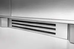
FIG. 2.
Pull the rainshield open.
WARNING! TIP OVER HAZARD. A child or
adult could tip the appliance, resulting in
property damage or bodily harm. Follow
these instructions to properly install
the anti-tip device. If the appliance is moved, verify
that the device is properly engaged before the normal
usage of the appliance commences.
ANTI-TIP BRACKET KIT:
• One (1) anti-tip bracket (Figure 1.1)
• Four (4) masonry 3/16” screws
• Eight (8) wood #12 – 2” screws
• Twelve (12) 1/4” washers
FOR ALL FULL SIZE RESIDENTIAL MODELS, THE ANTI-
TIP BRACKET ENGAGES WITH THE REAR LEVELING
LEGS TO SECURE THE UNIT. FOLLOW THESE STEPS
TO SECURE THE BRACKET BEFORE MOVING THE
UNIT INTO FINAL OPERATING POSITION.
1. Determine final location of the unit. For a FLUSH
install, measure back 24-31/32” (Dimension A)
from the surrounding cabinetry. For a PROUD
install, measure back 22-31/32” (Dimension B)
from the surrounding cabinetry. For either type of
install, place the anti-tip bracket centered in the
rough opening.
2. Using the bracket as a guide, drill pilot holes into the
wall/floor. It is recommended to secure the bracket
to as many floor joists and wall studs as possible.
3. Using the provided screws and washers, secure the
bracket to the wall/floor. Adjust the rear rollers to
just above their lowest position and move the unit to
its final position. Raise the rear rollers a minimum
of 1/8” to engage the bracket.
FIGURE 1.1 - ANTI-TIP BRACKET
987036
5.19.17 AL
TRUE RESIDENTIAL REFRIGERATION
UPRIGHT ANTI-TIP BRACKET INSTALLATION
30 INCH UNIT
22 31/32"
583mm
PROUD INSTALL
24 31/32"
634mm
FLUSH INSTALL
9 9/32"
236mm
9 9/32"
236mm
C
L
C
L
TR-30REF-R-SG-A
R
NOTE: DIMENSIONS MAY VARY BY ±
1
/
8
”
WARNING: To avoid a hazard due to instability of
the appliance, it must be fixed in accordance with
the instructions.
AVERTISSEMENT: Pour éviter tout risque dú a
l´instabilité del l´appareil, vous devez le fixer
conformément aux instructions.
Loading ...
Loading ...
Loading ...