Loading ...
Loading ...
Loading ...
W415-1101 / B / 07.29.13
8
EN
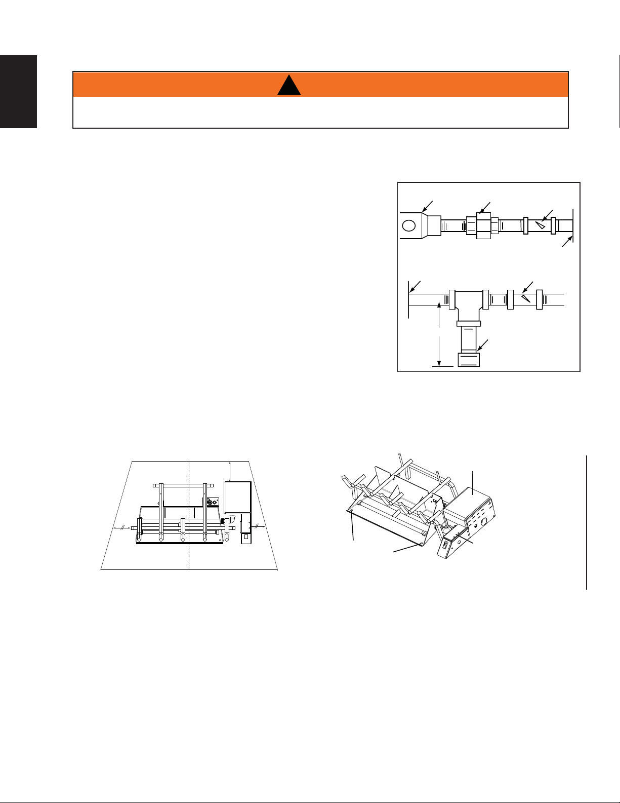
BATTERY
SUPPORT PLATE
(BATTERY CASE
SECURED INSIDE)
SECURING
HOLES/SCREWS
VALVE
HOUSING
MIN. 1.5”
(38.1mm)
!
WARNING
DO NOT CONNECT EITHER THE WALL SWITCH, THERMOSTAT OR GAS VALVE TO ELECTRICITY
(110 VOLTS).
This appliance must be isolated from the gas supply piping system by closing the individual manual shut off valve
during any pressure testing of the gas supply piping system at test pressure equal to or less than ½ psi (3.5 kPa)
A. Centre the burner pan and valve assembly in the fi replace opening, making sure the appliance is at least
1.5” (38.1mm) from the rear of the fi replace.
B. Secure the burner to the fi replace fl oor using the 2 screws
provided.
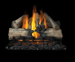
C. Install the gas line using piping ½” (12.7mm) in diameter or
greater to provide the full volume of gas to the appliance.
The installation of the gas line must be done to local and / or
National codes.
D. When rigid pipe is used an ANSI approved manual shut off and
a union must be installed upstream within the appliance cavity.
E. To ensure the appliance operates reliably install a sediment
trap upstream of the appliance within the structures of the
piping system.
F. When using propane, a regulator must be used between
the tank and the outside wall of the house to ensure the line
pressure does not exceed 14”(355.6mm) w.c. inside the house.
G. Check gas connections with a gas detection device to test for
leaks in the system. Soapy water mixture can also be used to check for leaks.
H. Once all the gas connections are tested for leaks, start the appliance. Follow the “OPERATING AND
LIGHTING INSTRUCTIONS” section to ensure the appliance is working properly before fi nishing.
Regulator
Union
Manual
Shut-Off
Valve
Wall
Shut-Off
Key
Sediment
Trap
Appliance
Appliance
3" (76.3mm)
3.2 GAS PIPING AND BURNER PLACEMENT
Loading ...
Loading ...
Loading ...