Loading ...
Loading ...
Loading ...
W415-1101 / B / 07.29.13
16
EN
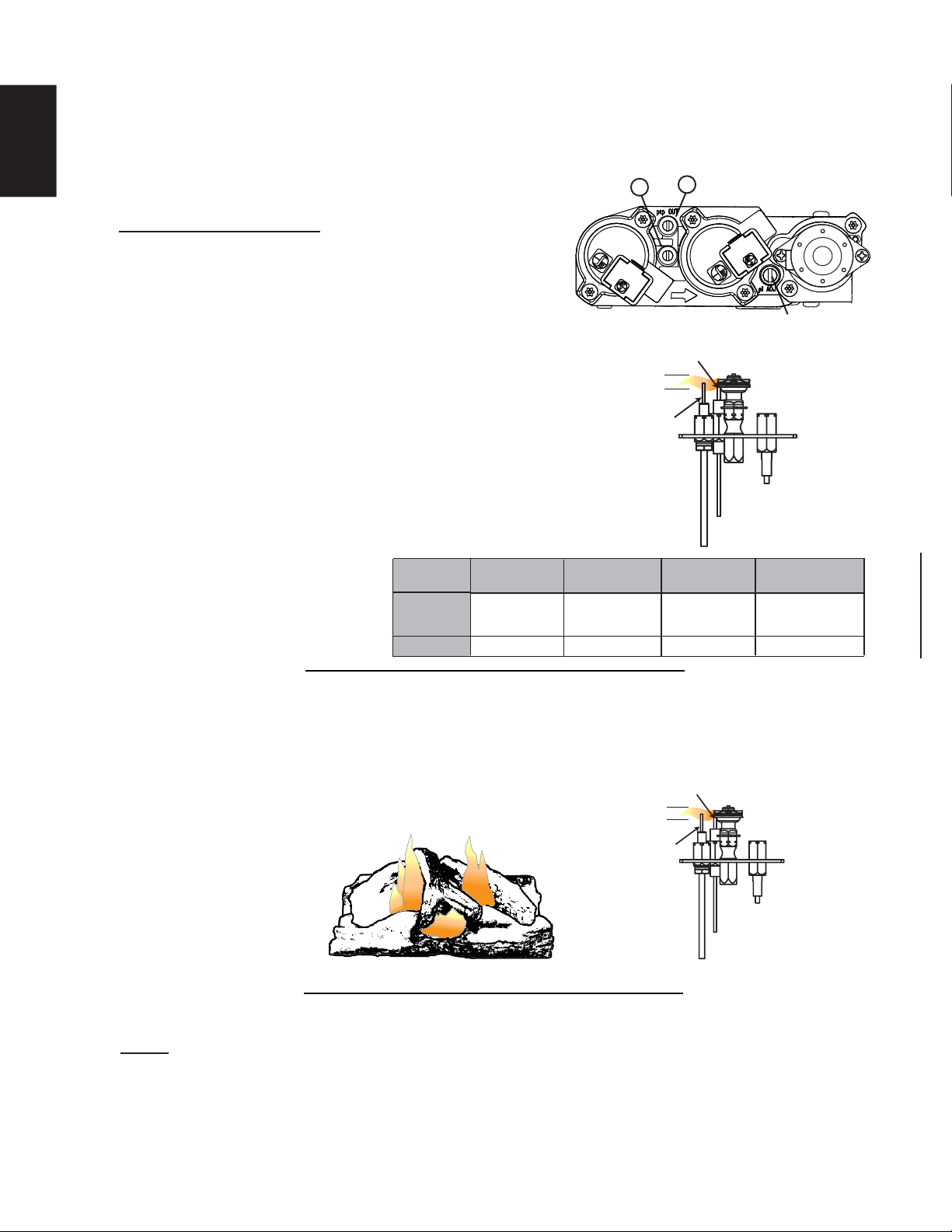
Adjust the pilot screw to provide properly sized fl ame. Turn in a
clockwise direction to reduce the gas fl ow.
Check Pressure Readings:
Inlet pressure can be checked by turning screw (A) counter-
clockwise 2 or 3 turns and then placing pressure gauge tubing
over the test point. Gauge should read as described on the chart
below. Check that main burner is operating on “HI”.
Outlet pressure can be checked the same as above using
screw (B). Gauge should read as described on the chart
below. Check that main burner is operating on “HI”.
AFTER TAKING PRESSURE READINGS, BE SURE TO
TURN SCREWS CLOCKWISE FIRMLY TO RESEAL. DO
NOT OVERTORQUE.
Leak test with a soap and water solution.
Prior to pilot adjustment, ensure that the pilot assembly
has not been painted. If overspray or painting of the pilot
assembly has occurred remove the paint from the pilot
assembly, or replace. Fine emery
cloth or sandpaper can be used to
remove the paint from the pilot hood,
electrode and fl ame sensor.
39.1C
A
B
PILOT SCREW
FLAME MUST ENVELOP
UPPER 3/8” (9.5mm) TO 1/2”
(12.7mm) OF FLAME SENSOR
PILOT
BURNER
ELECTRODE
FLAME
SENSOR
3/8” - 1/2”
(9.5mm - 12.7mm)
Pressure
Inlet
Outlet
Natural Gas
(inches)
Natural Gas
(millibars)
Propane
(inches)
Propane
(millibars)
7"
(MIN. 4.5")
3.5"
13"
(MIN. 11")
10"
17.4mb
(MIN. 11.2mb)
8.7mb
32.4mb
(MIN. 27.4mb)
24.9mb
It’s important to periodically perform a visual check of the pilot and burner fl ames. Compare them to the
illustration provided. If any fl ames appear abnormal call a service person.
FLAME MUST ENVELOP
UPPER 3/8” (9.5mm) TO 1/2”
(12.7mm) OF FLAME SENSO
R
PILOT
BURNER
ELECTRODE
FLAME
SENSOR
3/8” - 1/2”
(9.5mm - 12.7mm)
54.1B
7.0 ADJUSTMENTS
7.1 PILOT BURNER ADJUSTMENT
7.2 FLAME CHARACTERISTICS
NOTE: FLAME WILL VARY DEPENDING ON THE POSITION OF THE LOGS AND THE GRATE.
Loading ...
Loading ...
Loading ...