Pacic Accessory Corporation - Santa Ana, CA 92705
[email protected] • Voice: 866-931-8021 • Fax: 714-835-3233 • www.pac-audio.com
03-16-10
J1850
Class 2
VPW
Class 2
J1850
100011101111001001101100
111010000110110111001100
Arbitration
EOD
CRC
100011101111001001101100
111010000110110111001100
Class 2
Class 2
J1850
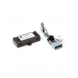
Radio Replacement Interface
with Nav Outputs for select
Volkswagen CANbus Vehicles With
or Without Premium Audio Systems
C2R-VW2
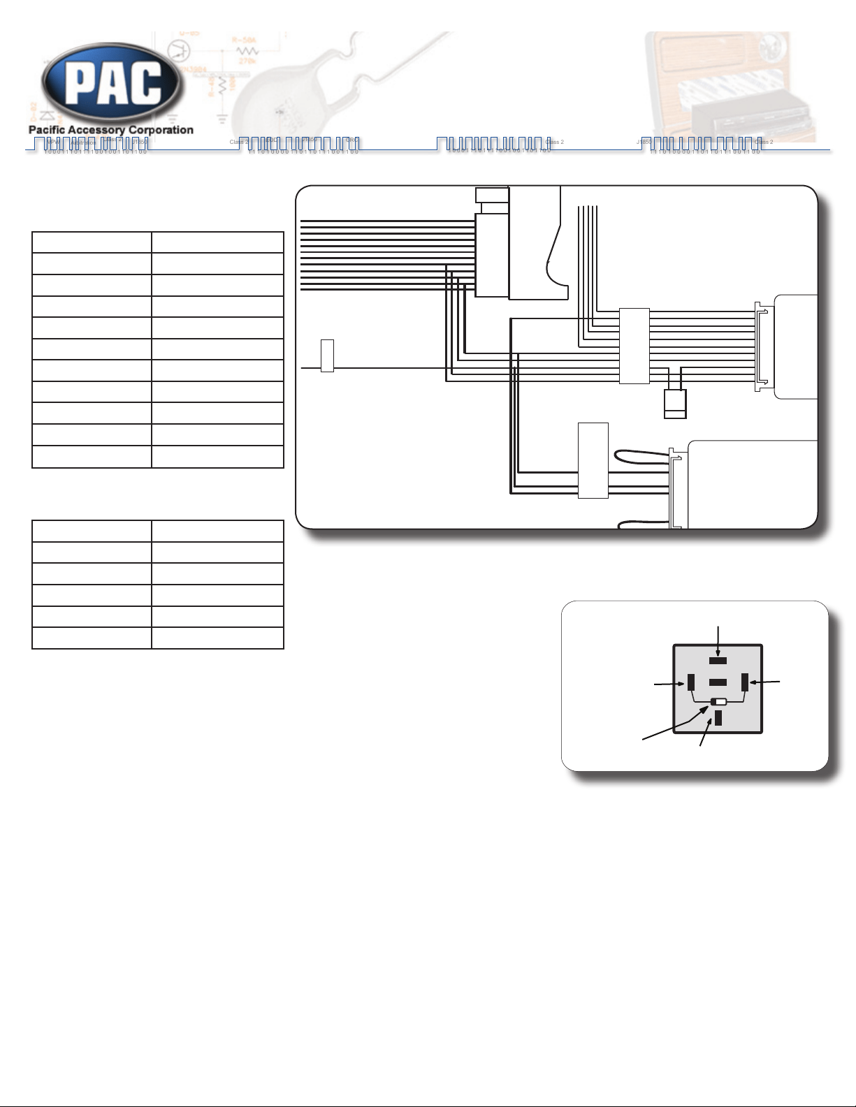
1. Vehicles with or without a factory amplier: Connect the aftermarket radio’s
front and rear speaker wires to the 16 pin plug.
2. The accessory output wire is located on the 11 pin CAN INTERFACE harness
- connect this wire to the radio’s
accessory wire. The accessory wire
supplies +12v, 1 amp max when key is
in the accessory or ignition position (see
g. 1: If more current is needed).
3. 11 pin plug (to CAN INTERFACE):
White/Green - Steering Wheel Control (SWC) output.1.
Green - Connect this wire to the radio’s reverse input wire only.2.
Orange/White - Connect this wire to the radio’s Illumination input wire only.3.
Violet/White - Connect this wire to the radio’s VSS input wire only.4.
Red/White - Connect this wire to the radio’s parking brake input wire only. 5.
Please Note: The parking brake wire will output a neg (-) trigger at all times until the vehicle is moving at a
speed of approximately 3 mph or faster.
Note: Do not connect these wires to any circuit other than the aftermarket radio’s wire harness.
4. 11 pin plug (to SWC INTERFACE):
This is a quick connection to a radio specic SWC interface. No additional connections are necessary other than radio
control connections. Plug the radio specic SWC interface in to this connector and program the radio specic SWC
interface for version 2. Do not cut the loops. Refer to the SWC interface instruction manual for the radio specic control
function programming order.
Fig. 1
(using a SPDT relay)
85 86
30
87
87a
Ground
High Current 12v
(Fused)
12v Acc.
From
Interface
New High
Current Output
Diode 1N4005
or equivelant
9
1
23456
78
1011
Accessory Output
+12volts 1amp max.
9 1
9
1
23456
78
1011
9 1
SWC Interface.
Program for Version 2
Radio Specific Steering
Wheel Control Interface
(Sold Separately)
Program SWC
Interface for Version 2.
CAN INTERFACE
Navigation outputs and
Amplifier Remote Input
See Chart for wire color
descriptions.
Radio Connections. See aside
Chart for color description.
Yellow Battery +12v
Black Ground
Blue Amp Turn On Input
White Front L + input
White / Black Front L - input
Grey Front R + input
Grey / Black Front R - input
Green Rear L + input
Green / Black Rear L - input
Purple Rear R + input
Purple / Black Rear R - input
Radio Connection Chart:
(Read the Installation Notes before making
connections to the provided radio harness)
CAN Interface Connection Chart:
Red Acc. Output (1 amp)
Red / White P.B. Output (-)
Purple / White VSS Output (Pulse)
Orange / White Illum. Output (+)
Green Reverse Output (+)
White / Green SWC Output
Page 1

Pacic Accessory Corporation - Santa Ana, CA 92705
[email protected] • Voice: 866-931-8021 • Fax: 714-835-3233 • www.pac-audio.com
03-16-10
1. 2002-2005 vehicles (excludes Touareg) - Can map track up and down, and volume up and down.
2. 2006-2010 vehicles with Eight button SWC (excludes Touareg) - Can map volume up and down, phone button, and star
button without effecting the Multi Function Display (MFD). Arrow up and down can be mapped but will control MFD.
3. 2009-2010 vehicles with 12 button SWC (excludes Touareg) - Can map left side of steering wheel (volume up and down, track
left and right, phone, and mute buttons) without effecting MFD. Arrow up and down on right side can be mapped but will control
MFD.
4. 2004-2010 Touareg - Can only map volume up and down
5. Refer to the aftermarket radio’s instruction manual for testing VSS, Reverse, Parking Brake and Illumination outputs. PLEASE
NOTE: The Parking Brake is speed based. The C2R-VW2 will automatically send a Parking Brake signal when going below 4
Mph. The signal will shut off when going above 4 Mph.
6. 2002-2005 Vehicles - The C2R-VW2 does not provide a Reverse output trigger. This signal is unavailable on the data bus.
You must be replacing a factory Double-DIN radio. If the vehicle came equipped with a Single-DIN radio, the C2R-VW2 is not
compatible.
7. 2004-2007 Touareg - Does not retain digital audio amplied system seen when the vehicles is equipped with factory navigation
radio
SWC Programming & Installation Notes
DISCLAIMER: Under no circumstances shall the manufacturer or the distributors of the C2R-VW2 be held liable for consequential damages sustained in
connection with the C2R-VW2. The manufacture and it’s distributors will not, nor will they authorize any representative or any other individual to assume
obligation or liability in relation to the C2R-VW2 other than its replacement.
Page 2