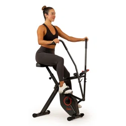

TOTAL BODY BIKE
SF-B2710
USER MANUAL
IMPORTANT! Please retain owner’s manual for maintenance and adjustment instructions. Your
satisfaction is very important to us, PLEASE DO NOT RETURN UNTIL YOU HAVE CONTACTED
US: [email protected] or 1- 877 - 90SUNNY (877-907-8669).

1
IMPORTANT SAFETY INFORMATION
We thank you for choosing our product. To ensure your safety and health, please use this
equipment correctly. It is important to read this entire manual before assembling and using the
equipment. Safe and effective use can only be achieved if the equipment is assembled, maintained,
and used properly. It is your responsibility to ensure that all users of the equipment are informed of
all warnings and precautions.
1. Before starting any exercise program, you should consult your physician to determine if you
have any medical or physical conditions that could put your health and safety at risk or prevent
you from using the equipment properly. Your physician’s advice is essential if you are taking
any medication that affects your heart rate, blood pressure, or cholesterol level.
2. Be aware of your body’s signals. Incorrect or excessive exercise can damage your health. Stop
exercising if you experience any of the following symptoms: pain, tightness in your chest,
irregular heartbeat, shortness of breath, lightheadedness, dizziness, or feelings of nausea. If
you do experience any of these conditions, you should consult your physician before continuing
with your exercise program.
3. Keep children and pets away from the equipment. The equipment is designed for adult use only.
4. Use the equipment on a solid, flat level surface with a protective cover for your floor or carpet.
To ensure safety, the equipment should have at least 2 feet (60 CM) of free space all around it.
5. Ensure that all nuts and bolts are securely tightened before using the equipment. The safety of
the equipment can only be maintained if it is regularly examined for damage and/or wear and
tear.
6. Always use the equipment as indicated. If you find any defective components while assembling
or checking the equipment, or if you hear any unusual noises coming from the equipment during
exercise, discontinue use of the equipment immediately and do not use until the problem has
been rectified.
7. Wear suitable clothing while using the equipment. Avoid wearing loose clothing that may
become entangled in the equipment.
8. Do not place fingers or objects into the moving parts of the equipment.
9. The maximum weight capacity of this unit is 265 pounds (120KG).
10. The equipment is not suitable for therapeutic use.
11. To avoid bodily injury and/or damage to the product or property, proper lifting and moving are
required.
12. Your product is intended for use in cool and dry conditions. You should avoid storage in extreme
cold, hot or damp areas as this may lead to corrosion and other related problems.
13. This equipment is designed for indoor and home use only; it is not intended for commercial use.
2
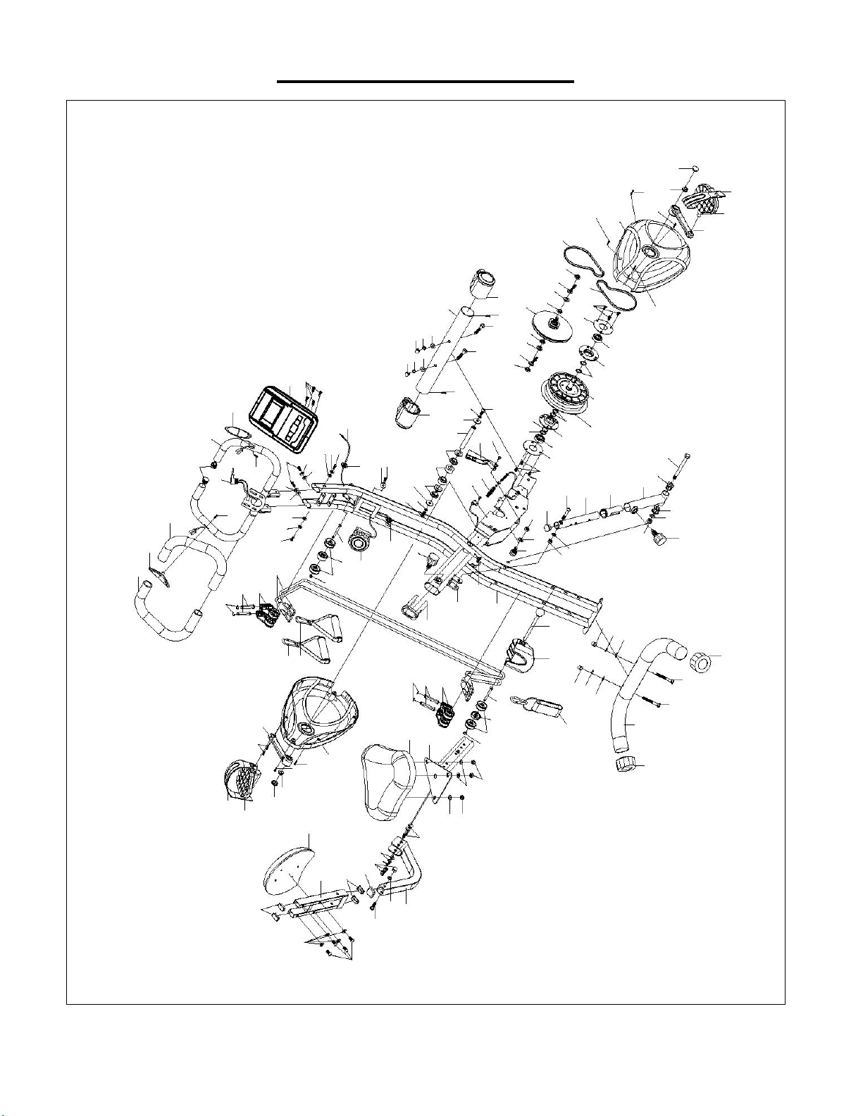
EXPLODED DIAGRAM
92R
12R
10
11
13R
9
14
15R
9
14
30
29
24
25
27
24
24
26
26
25
28
8R
9
1
1
7
2
2
3
3
91
4
4
9
8L
86
85
31
3
32
33
34
35
34
32
3
31
81
82
53
39
87
88
75
88
88
88
87
87
75
90
90
16
17
18
19
20
21
22
20
19
18
20
23
17
16
40
41
42
41
43
45
44
46
47
48
49
50
51
44
43
52
16
36
37
38
84
49
9
9
83
91
89
89
66
65
64
79
63
62
61
60
80
53
45
53
54
55
57
58
59
66
1
1
2
2
3
3
4
4
65
64
60
61
62
63
78
78
51
50
50
51
67
68
69
15L
14
13L
9
14
11
10
12L
92L
5
5
6
50
3
4
50
70
72
71
73
77
76
72
75
74
56

3
PARTS LIST
No.
Description
Spec.
Qty.
No.
Description
Spec.
Qty.
1
Carriage Bolt
M8*65
4
48
Screw
M8*48
1
2
Curved Washer
∅8*∅18
4
49
End Cap
∅25.4
3
3
Spring Washer
∅8*∅14
8
50
Flat Washer
∅8*∅18
7
4
Cap Nut
M8
7
51
Nylon Nut
M8
4
5
Adjustable End Cap
∅50
2
52
Press Wheel
1
6
Rear Stabilizer
∅50*395mm
1
53
Cap
15*20
3
7
Front Stabilizer
∅50*395mm
1
54
Rear Main Frame
1
8L/R
Front Wheel L/R
∅50
2
55
Front Main Frame
1
9
Screw
M4*20
8
56
Bushing
30*60
1
10
Crank Cover
∅23.5*8
2
57
Pin
∅10*116
1
11
Stop Nut
M10
2
58
Cover
1
12L/R
Pedal (L/R)
1/2"
2
59
Ankle Strap
1
13L/R
Crank (L/R)
5 Inch
2
60
Hex Bolt
M6*60
2
14
Screw
M4*20
4
61
Wheel
∅34*16
2
15L/R
Chain Cover (L/R)
2
62
Wheel
∅38*14
4
16
Screw
M6*12
7
63
Nut
M6
2
17
Round Plate
∅74*∅30*1.5
2
64
Bracket
2
18
Bearing
6003Z
2
65
Pin
∅10*53
4
19
Bearing Bracket
∅35*∅74*12.5
2
66
Ring
∅10
4
20
Ring
∅17.5*∅20*1.0
5
67
Seat Tube
1
21
Pulley
1
68
Seat
1
22
Magnetic Bracket
∅152*1.3kg
1
69
Carriage Bolt
M8*45
2
23
Curved Washer
∅17.5*∅21*0.3
1
70
Backrest Tube
1
24
Nut
M10
3
71
Cap
30*30mm
1
25
Adjustable Nut
2
72
Cap
15*30mm
4
26
Flat Washer
∅10.5*20*2.0
2
73
Carriage Bolt
M8*75
1
27
Nut
M10*3.0
1
74
Screw
M6*40
4
28
Small Pulley
∅14*94
1
75
Flat Washer
∅6*∅14
6
29
Belt
230J
1
76
Back Tube
1
30
Belt
220J
1
77
Backrest
1
31
Hex Nut
M8*20
2
78
Handle
2
32
Big Flat Washer
∅8.5*∅24
2
79
Exercise Band
∅6*1080mm
2
33
Axle
∅15*104
1
80
Tension Knob
1
34
Bushing
∅20*∅25*10mm
4
81
Flat Washer
∅5.5*∅12
1
35
Bushing
∅20*∅24*20mm
2
82
Screw
M5*50
1
36
Magnetic
117*33
1
83
Hand Pulse Wire
1
37
Tension Spring
1
84
Handlebar
1
38
Screw
M6*10
1
85
Screw
M5*12
4
39
Sensor Wire
1
86
Meter
1
40
Bolt
M10*110
1
87
Screw
M6*15
4
41
Bushing
∅28*∅10.5
2
88
Spring Washer
∅6*∅14
4
42
Adjustable Tube
1
89
Foam Grip
∅25.4
2
43
Flat Washer
∅10.5*∅22
2
90
Curved Washer
∅6*∅14
2
44
Nut
M10
2
91
Hand Pulse
2
45
Release Knob
M16
2
92L/R
Pedal Strap
2
46
Bushing
32*1.5/25*1.5
1
A
Spanner
S13-14-15
1
47
Adjustable Set
1
B
Allen Wrench
S5
1

4
HARDWARE PACKAGE
Ordering Replacement Parts (U.S. and Canadian Customers only)
Please provide the following information in order for us to accurately identify the part(s) needed:
✓ The model number (found on cover of manual)
✓ The product name (found on cover of manual)
✓ The part number found on the “EXPLODED DIAGRAM” and “PARTS LIST” (found near the front
of the manual)
Please contact us at [email protected] or 1- 877 - 90SUNNY (877-907-8669).

5
ASSEMBLY INSTRUCTIONS
We value your experience using Sunny Health and Fitness products. For assistance with parts or
troubleshooting, please contact us at s[email protected] or 1-877-90SUNNY (877-907-
8669).
STEP 1
Loosen and pull the Release Knob (No. 45) from the
folded Rear and Front Main Frame (No. 54 and No.
55), then lower the Adjustable Set (No. 47) and
reinsert the Release Knob (No. 45) into the upper hole
or middle hole of Adjustable Set (No. 47). Retighten
the Release Knob (No. 45) by hand.
NOTE: There are 3 modes for the bike: bike,
recumbent bike, folding. There are 3 holes in the
Adjustable Set (No. 47). To set the mode, insert the
Release Knob (No. 45) into the corresponding hole in
the Adjustable Set (No. 47) and tighten.
Upper Hole = Bike, Middle Hole = Recumbent
bike, Bottom Hole = Folding
Attach Rear Stabilizer (No. 6) to the Front Main
Frame (No. 55) using 2 Curved Washers (No. 2), 2
Spring Washers (No. 3), 2 Carriage Bolts (No. 1),
and 2 Cap Nuts (No. 4). Secure and tighten with
Spanner (No. A).
Attach Front Stabilizer (No. 7) to Rear Main Frame
(No. 54) with 2 Curved Washers (No. 2), 2 Spring
Washers (No. 3), 2 Carriage Bolts (No. 1), and 2 Cap
Nuts (No. 4). Secure and tighten with Spanner (No.
A).

6
We value your experience using Sunny Health and Fitness products. For assistance with parts or
troubleshooting, please contact us at [email protected] or 1-877-90SUNNY (877-
907-8669).
STEP 2
The Left Pedal (No. 12L) is marked L and the Right
Pedal (No. 12R) is marked R. Turn the resistance knob
all the way to the right until the cranks are immobilized.
Align the Left Pedal (No. 12L) with the Left Crank (No.
13L) at 90°. Gently insert the Left Pedal (No. 12L) into
the Left Crank (No. 13L) and turn the Left Pedal (No.
12L) counterclockwise. Use Spanner (No. A) to
tighten.
Attach the Right Pedal (No. 12R) with the Right Crank
(No. 13R) at 90°. Gently insert the Right Pedal (No.
12R) into the Right Crank (No. 13R) and turn the Right
Pedal (No. 12R) clockwise. Use Spanner (No. A) to
tighten.
Attach the 2 Pedal Straps (No. 92L/R) to the Left and
Right Pedals (No. 12L/R).

7
We value your experience using Sunny Health and Fitness products. For assistance with parts or
troubleshooting, please contact us at [email protected] or 1-877-90SUNNY (877-
907-8669).
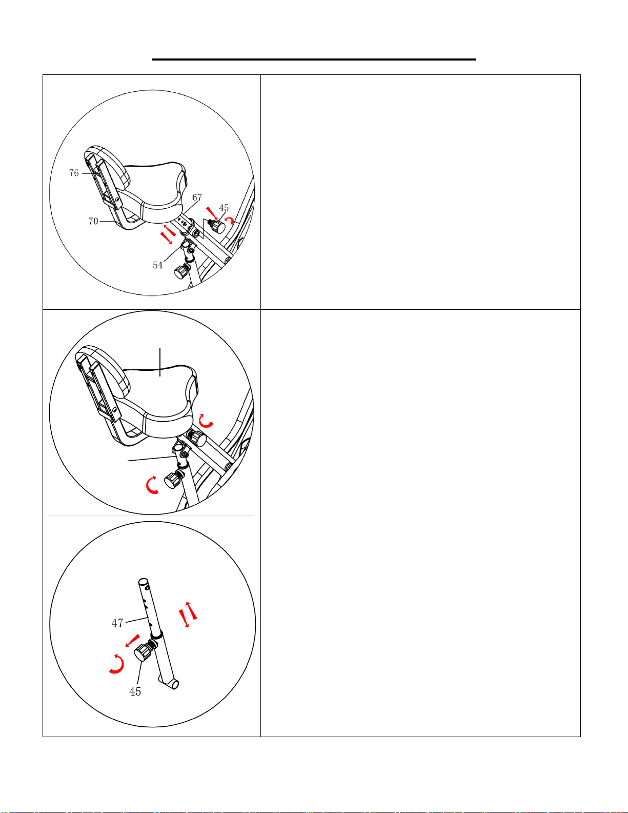
STEP 3
Remove the pre-assembled 3 Nylon Nuts (No. 51) and
3 Flat Washers (No. 50) from the back of the Seat (No.
68) with Spanner (No. A).
Attach the Seat (No. 68) to the Seat Tube (No. 67) with
3 Nylon Nuts (No. 51) and 3 Flat Washers (No. 50)
that were removed. Secure and tighten with Spanner
(No. A).
Remove the pre-assembled 2 Carriage Bolts (No. 69),
2 Flat Washers (No. 50), 2 Cap Nuts (No. 4), and 2
Spring Washers (No. 3) from the Backrest Tube (No.
70) with Spanner (No. A).
Attach the Backrest Tube (No. 70) to the Seat Tube
(No. 67) with 2 Carriage Bolts (No. 69), 2 Flat
Washers (No. 50), 2 Spring Washers (No. 3), and 2
Cap Nuts (No. 4) that were removed. Secure and
tighten with Spanner (No. A).
Take out 4 Screws (No. 74) and 4 Flat Washers (No.
75) from the plastic bag for Backrest (No. 77). Then
attach Backrest (No. 77) to Backrest Tube (No. 70)
with 4 Screws (No. 74) and 4 Flat Washers (No. 75).
Secure and tighten with Allen Wrench (No. B).

8
We value your experience using Sunny Health and Fitness products. For assistance with parts or
troubleshooting, please contact us at [email protected] or 1-877-90SUNNY (877-907-
8669).
STEP 4
Loosen and pull out Release Knob (No. 45), then
insert Seat Tube (No. 67) into Rear Main Frame (No.
54). Insert and tighten Release Knob (No. 45) to
secure.
STEP 5
Attach Handlebar (No. 84) to the Front Main Frame
(No. 55) with 4 Screws (No. 87), 2 Flat Washers (No.
75), 2 Curved Washers (No. 90), and 4 Spring
Washers (No. 88). Secure and tighten with Allen
Wrench (No. B).
9
We value your experience using Sunny Health and Fitness products. For assistance with parts or
troubleshooting, please contact us at [email protected] or 1-877-90SUNNY (877-907-
8669).
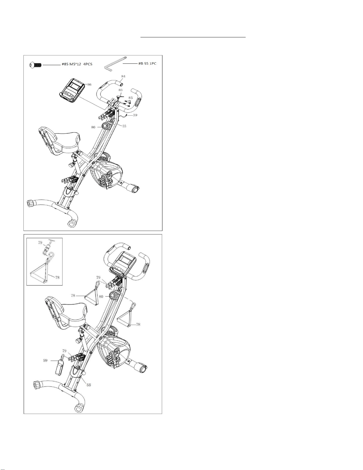
STEP 6
Remove 4 Screws (No. 85) from the back of the Meter
(No. 86) with Allen Wrench (No. B).
Attach Meter (No. 86) to the Front Main Frame (No.
55) with 4 Screws (No. 85) that were removed. Insert
Sensor Wire (No. 39) into the hole on the back of the
Meter (No. 86). Make sure the wire does not get
caught when you attach the meter.
Insert Hand Pulse Wire (No. 83) into the hole on the
back of the Meter (No. 86).
STEP 7
Connect Ankle Strap (No. 59) to the Exercise Bands
(No. 79) above the Cover (No. 58).
Connect the 2 Handles (No. 78) to the Exercise Bands
(No. 79) above the Tension Knob (No. 80).
The assembly is complete!

10
BATTERY INSTALLATION & REPLACEMENT
BATTERY INSTALLATION:
1. Take out 2 AA batteries from meter box;
2. Press the buckle of battery cover on the Meter (No. 86), then remove battery cover;
3. Install 2 AA batteries into the battery case on the back of the Meter (No. 86). Pay attention to the
battery + and – poles before installing.
4. Press the buckle of battery cover, then put the battery cover back to the back of the Meter (No. 86).
5. The installation is complete!
BATTERY REPLACEMENT:
1. Press the buckle of battery cover on the back of the Meter (No. 86), then remove battery cover;
2. Remove the 2 old AA batteries in the battery case and install 2 new AA batteries into the battery
case on the back of the Meter (No. 86). Pay attention to the battery + and – poles before installing.
3. Press the buckle of battery cover, then put the battery cover back to the back of the Meter (No. 86).
4. The replacement is complete!
Battery
Battery Cover
86

11
ADJUSTMENTS & USAGE GUIDE
ADJUSTING THE TENSION OF THE BIKE
Adjust the tension of the bike by rotating the Tension
Knob (No. 80) clockwise to increase the level of
resistance. Rotate the Tension Knob (No. 80)
counterclockwise to decrease the level of resistance.
Tension levels are set at Level 1 being the lowest and
Level 8 being the highest.
ADJUSTING THE TENSION OF THE EXERCISE BAND
Adjust the tension of the Exercise Bands (No. 79) by
pulling out Pin (No. 57) and moving Cover (No. 58) to
desired setting. Insert Pin (No. 57) into one of the three
holes.
79
12
ADJUSTMENTS & USAGE GUIDE
ADJUSTING THE SEAT HEIGHT
To adjust the seat height, loosen Release Knob (No. 45)
by turning counter-clockwise and pull Release Knob (No.
45) outward, then raise or lower the Seat Tube (No. 67)
to desired height. Once adjusted, re-insert and tighten
Release Knob (No. 45) by turning clockwise to secure
the seat tube in place.
Note: when making adjustments, you will see a limit mark
on the Seat Tube (No. 67). Do not lift the Seat Tube (No.
67) past the mark.
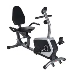
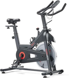
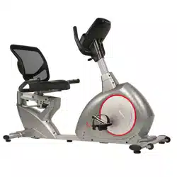
ADJUSTING THE BIKE MODE
There are three modes for the bike: BIKE, RECUMBENT
BIKE, FOLDING.
There are three holes on Adjustable Set (No. 47).
Upper Hole = BIKE, Middle Hole = RECUMBENT BIKE,
Bottom Hole = FOLDING
To change the mode, loosen Release Knob (No. 45) by
turning counterclockwise and pull Release Knob (No.
45) outward, then raise or lower the Seat (No. 68) to
desired hole on Adjustable Set (No. 47). Once adjusted,
re-insert and tighten Release Knob (No. 45) by turning
clockwise to secure the Adjustable Set (No. 47) in place.
68
47

13
ADJUSTMENTS & USAGE GUIDE
FOLDING THE BIKE
Loosen and pull out the Release Knob (No. 45), fold the
bike, and then engage Release Knob (No. 45) into the
bottom hole of the Adjustable Set (No. 47) and tighten.
MOVING THE BIKE
First fold the bike according to the instructions above.
To move the bike, hold Handlebar (No. 84) and tilt the
bike until the movable wheels located on the front
stabilizer end cap touch the ground. With the wheels on
the ground, you can transport the bike to the desired
location with ease.
CLEANING
The bike can be cleaned with a soft, clean, and damp cloth. Do not use abrasives or solvents on
plastic parts. Please wipe your perspiration off the bike after each use. Be careful not get excessive
moisture on the meter display panel as this might cause electrical hazard or electronics to failure.
Please keep the bike, especially the meter out of direct sunlight to prevent screen damage.
Please inspect all assembly bolts and pedals on the bike for proper tightness every week.
STORAGE
Store the bike in a clean and dry environment, away from children.
TROUBLESHOOTING
PROBLEM
SOLUTION
There is no display on
the meter.
1. Remove the meter and verify the wire that comes from the meter is
properly connected to the wire that comes from front main frame.
2. Check if the batteries are correctly positioned and battery springs
are in proper contact with batteries.
3. The batteries in the meter may be unresponsive. If this occurs,
change the batteries.
The bike wobbles
when in use.
• Turn the adjustable end cap on the rear stabilizer as needed to level
the bike.
The bike makes a
squeaking noise when
in use.
• The bolts may have become loose on the bike. Please inspect all
the bolts and tighten any loose bolts.
47
45
47
45
84
14
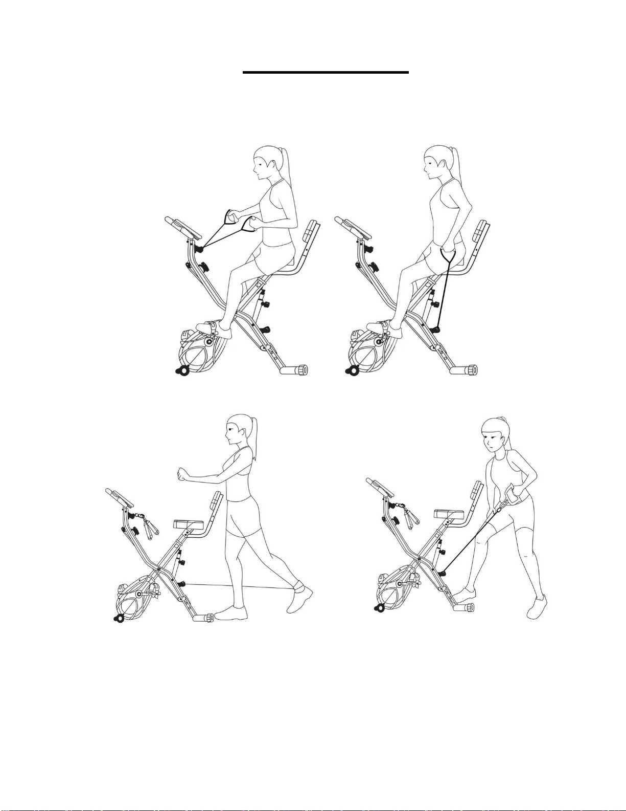
USING THE BIKE
Using the Total Body Bike, you can do a variety of exercises as shown below.
15
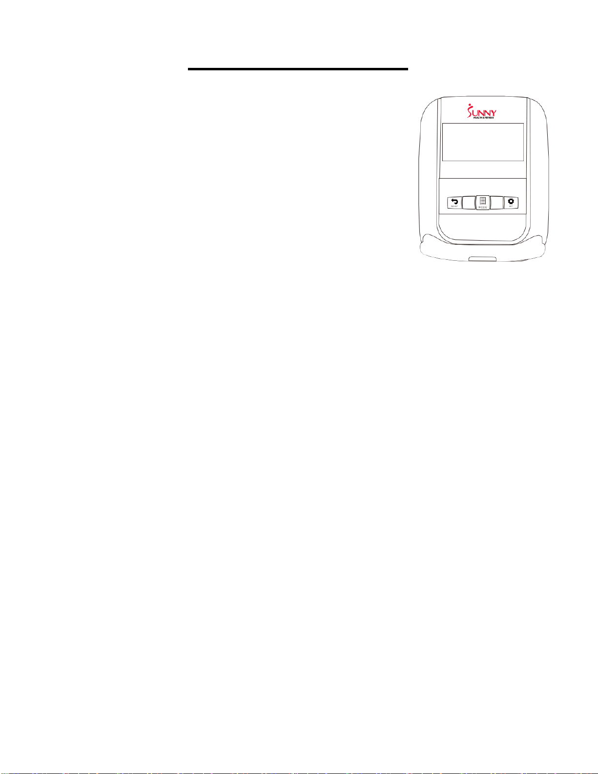
METER INSTRUCTIONS
AUTO ON/OFF: The meter will turn on when you press MODE key.
After 4 minutes of inactivity, the meter will shut off automatically.
FUNCTION BUTTONS
MODE: Press and hold for 2 seconds to turn on meter.
SET: During STOP mode, press to increase the value of TIME,
DISTANCE or CALORIES.
RESET: During STOP mode, press to clear value or set value to zero.
FUNCTIONS
1. SCAN: Display will automatically cycle through the functions in the following order: TIME –
SPEED – DISTANCE – CALORIES – ODO – PULSE.
2. TIME: Shows the workout time elapsed (0:00 to 99:59).
3. SPEED: Displays your workout speed (0.0 to 99:0 miles per hour).
4. DISTANCE: Displays the distance of each workout (0.00 to 99.99 miles).
5. CALORIES: Displays the estimated calories burned.
6. PULSE: Displays your pulse in beats per minute.
7. ODO (ODOMETER): Displays the total accumulated distance. (0.0 to 999.9 miles).
OPERATING INSTRUCTIONS
Press MODE to turn on the meter. Press MODE to select SCAN or to select a function to be
displayed.
COUNTDOWN FUNCTION (TIME, DISTANCE, or CALORIES)
During STOP mode, press MODE to select TIME, DISTANCE, or CALORIES. Press SET to increase
the value. Press MODE to accept the set value. When you start pedaling, the meter will countdown.
Once the meter has reached 0, it will beep and start counting again.
BATTERIES
This meter uses 2 AA batteries, which are included. If the display appears incorrectly or becomes
difficult to read, please install new batteries. Always change all batteries at the same time. Do not
mix battery types and do not mix old and new batteries. Dispose of old batteries according to your
regional guidelines.
Version 1.8

16