
SMART TOTAL BODY X-BIKE
SF-B224090
USER MANUAL
IMPORTANT! Please retain owner’s manual for maintenance and adjustment instructions. Your
satisfaction is very important to us, PLEASE DO NOT RETURN UNTIL YOU HAVE CONTACTED
US: [email protected] or 1-877-90SUNNY (877-907-8669).

1
IMPORTANT SAFETY INFORMATION
We thank you for choosing our product. To ensure your safety and health, please use this
equipment correctly. It is important to read this entire manual before assembling and using the
equipment. Safe and effective use can only be achieved if the equipment is assembled, maintained,
and used properly. It is your responsibility to ensure that all users of the equipment are informed of
all warnings and precautions.
1. Before starting any exercise program, you should consult your physician to determine if you
have any medical or physical conditions that could put your health and safety at risk or prevent
you from using the equipment properly. Your physician’s advice is essential if you are taking
medication that affects your heart rate, blood pressure, or cholesterol level.
2. Be aware of your body’s signals. Incorrect or excessive exercise can damage your health. Stop
exercising if you experience any of the following symptoms: pain, tightness in your chest,
irregular heartbeat, shortness of breath, lightheadedness, dizziness, or feelings of nausea. If
you do experience any of these conditions, you should consult your physician before continuing
with your exercise program.
3. Keep children and pets away from the equipment. The equipment is designed for adult use only.
4. Use the equipment on a solid, flat level surface with a protective cover for your floor or carpet.
To ensure safety, the equipment should have at least 2 feet (60 CM) of free space all around it.
5. Ensure that all nuts and bolts are securely tightened before using the equipment. The safety of
the equipment can only be maintained if it is regularly examined for damage and/or wear and
tear.
6. Always use the equipment as indicated. If you find any defective components while assembling
or checking the equipment, or if you hear any unusual noises coming from the equipment during
exercise, discontinue use of the equipment immediately and do not use until the problem has
been rectified.
7. Wear suitable clothing while using the equipment. Avoid wearing loose clothing that may
become entangled in the equipment.
8. Do not place fingers or objects into the moving parts of the equipment.
9. The maximum weight capacity of this unit is 300 lbs (135 kg).
10. The equipment is not suitable for therapeutic use.
11. To avoid bodily injury and/or damage to the product or property, proper lifting and moving are
required.
12. Your product is intended for use in cool, dry conditions. You should avoid storage in extreme
cold, hot, or damp areas as this may lead to corrosion and other related problems.
13. This equipment is designed for indoor and home use only; it is not intended for commercial use.
2
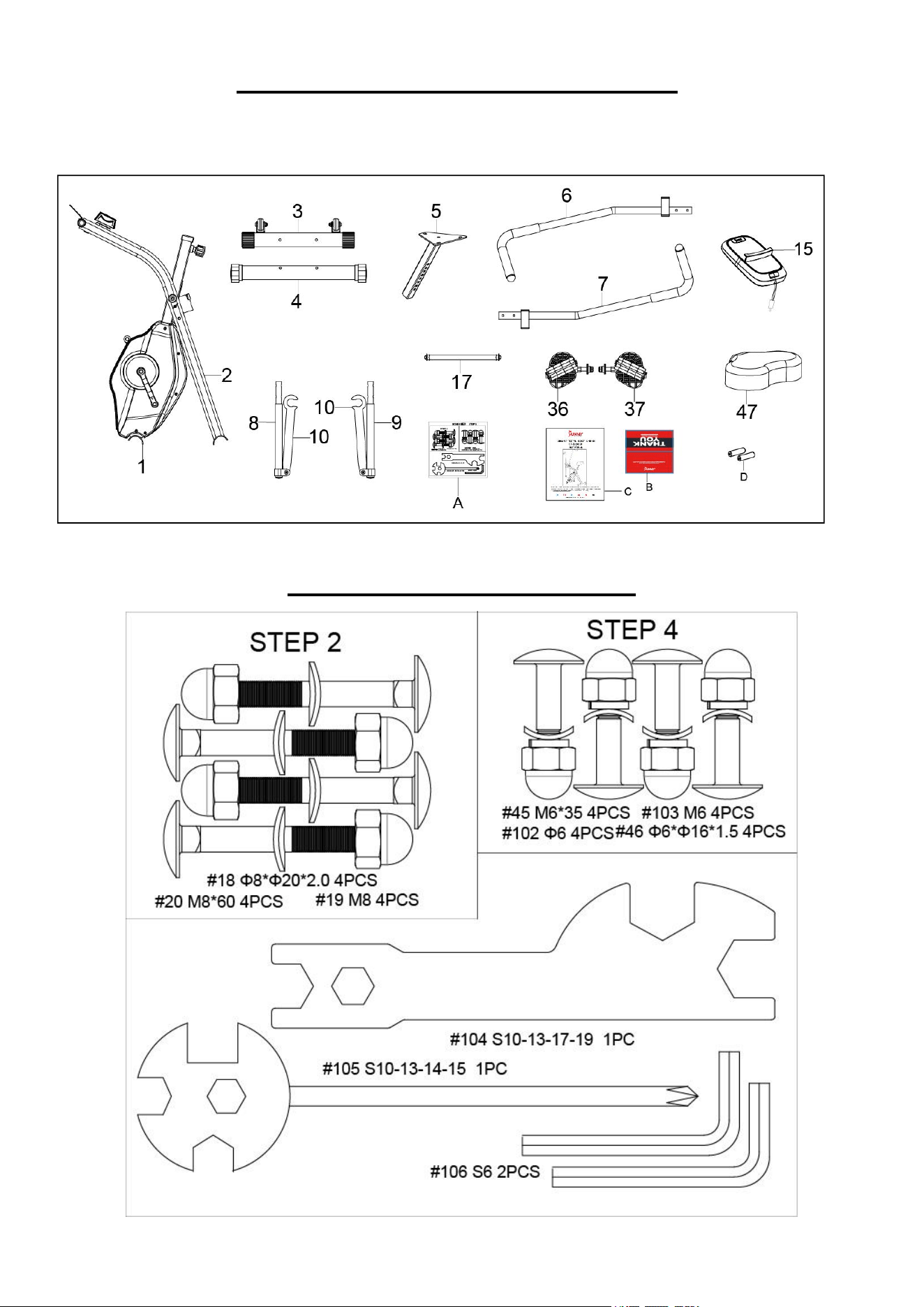
PRE-ASSEMBLY CHECK LIST
Before you start to assemble, please make sure all parts are included
HARDWARE PACKAGE
3
ASSEMBLY INSTRUCTIONS
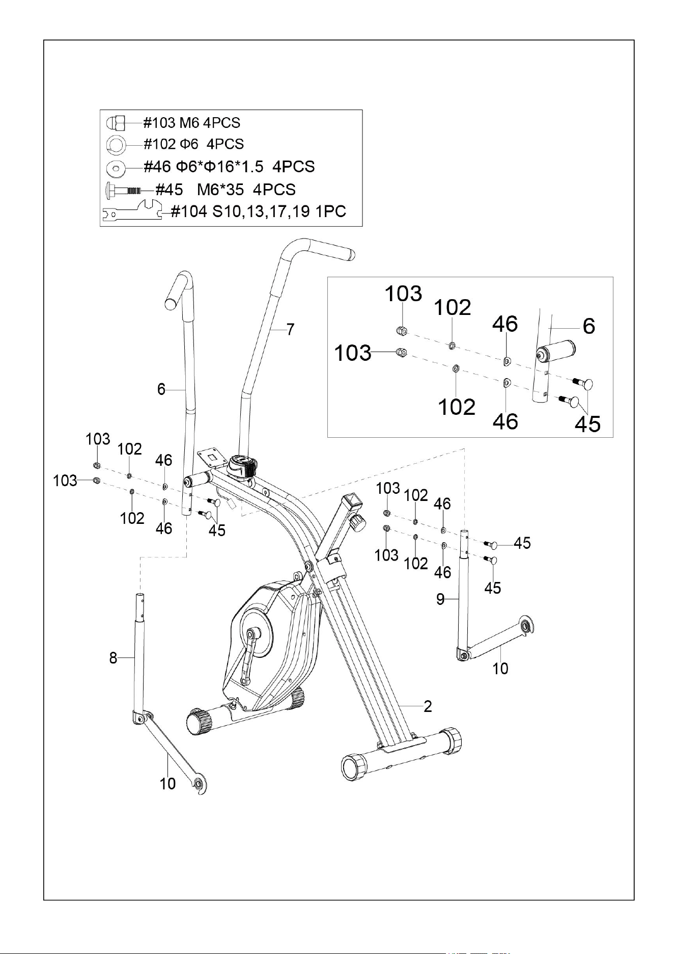
STEP 1
4
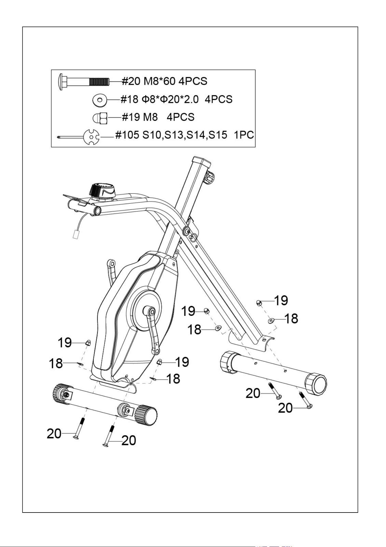
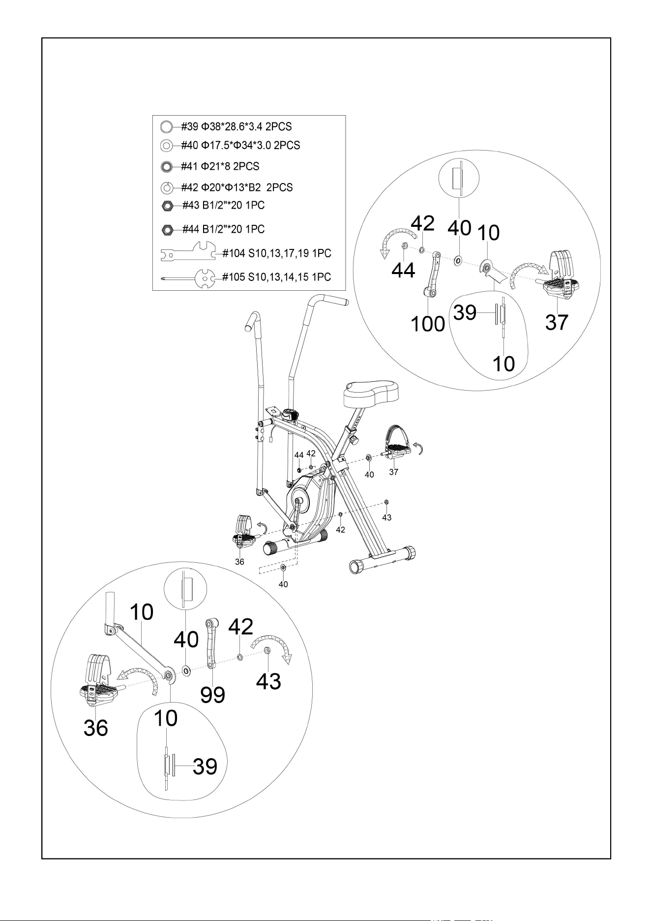
STEP 2
5
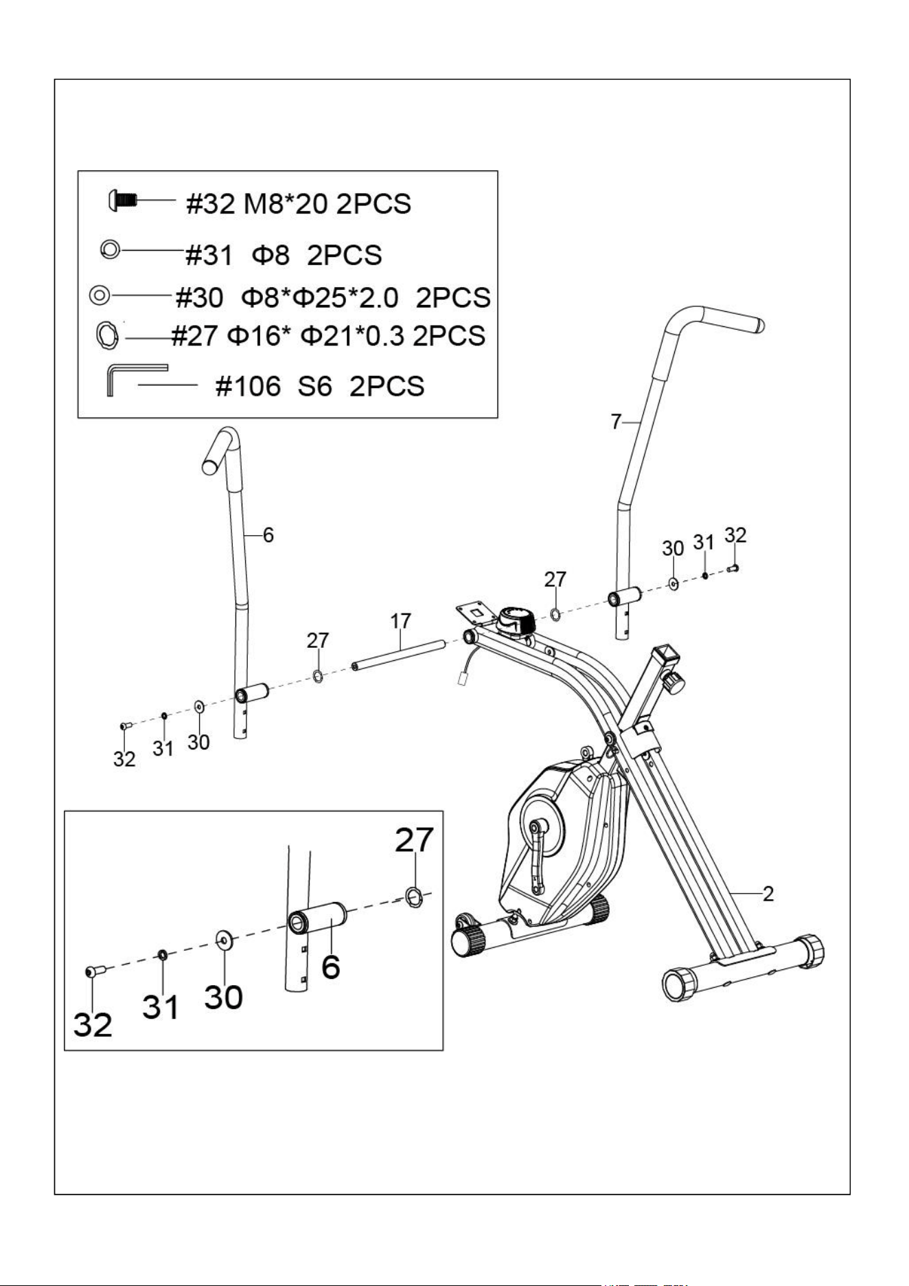
STEP 3
6
STEP 4
7
STEP 5
8
STEP 6

9
STEP 7
10
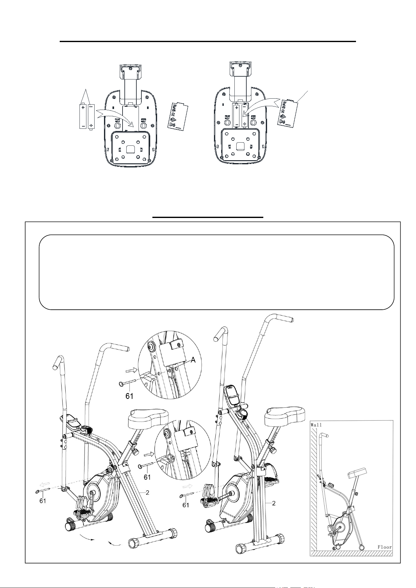
BATTERY INSTALLATION & REPLACEMENT
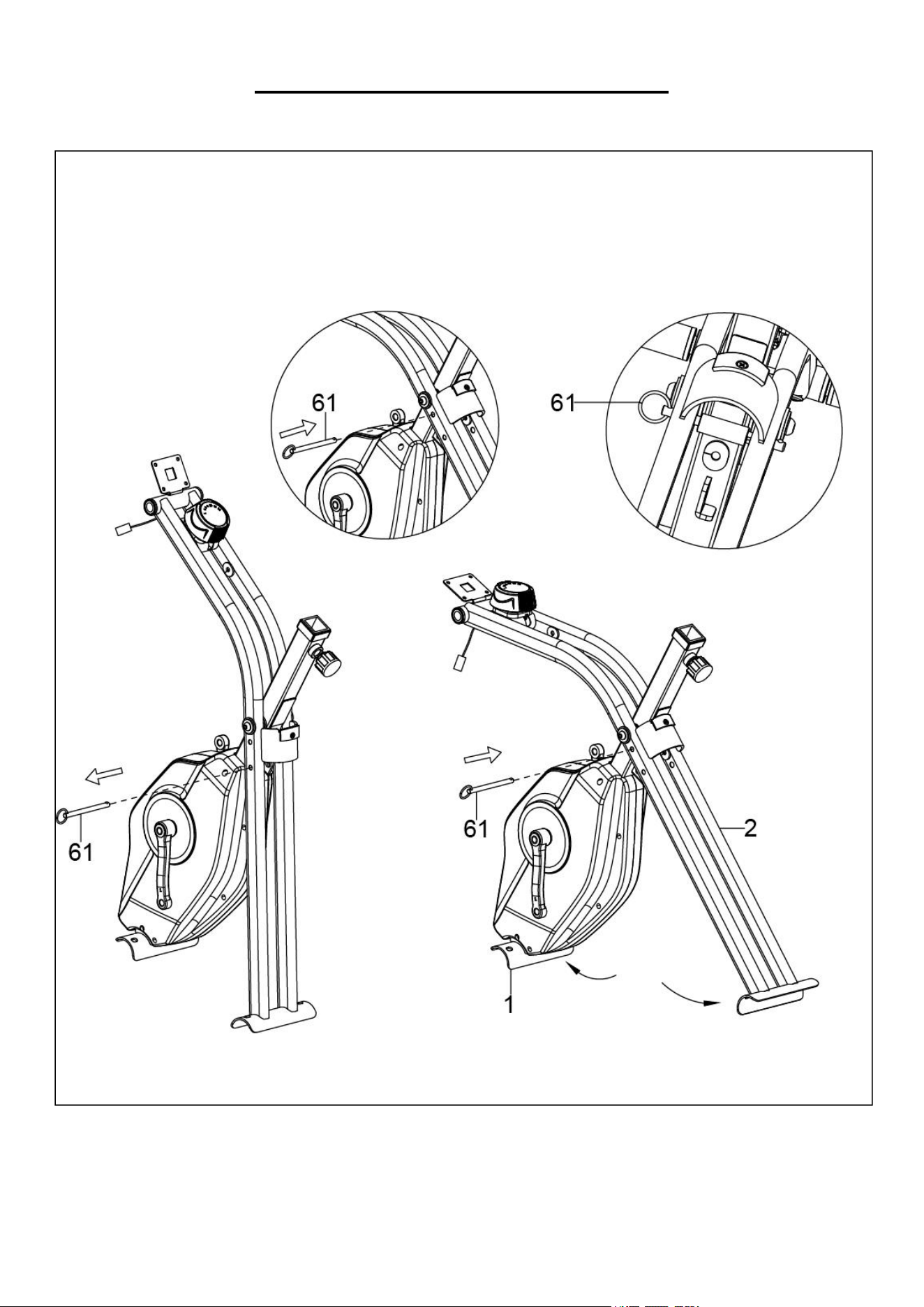
FOLDING GUIDE
Pull the Ring Spring Pin (No. 61) out and fold the Rear Support Frame (No. 2) to the Front Main Frame
Post (No. 1) as the direction of the arrow shown in Figure.
Turn the Ring Spring Pin (No. 61) into the hole A in the steel plate of the Front Main Frame Post (No.1).
WARNING: WATCH OUR HANDS WHEN YOU FOLD THE BIKE.
Dispose the old battery (1.5V, AAA) according to your regional guidelines.
Battery
Battery Cover
11
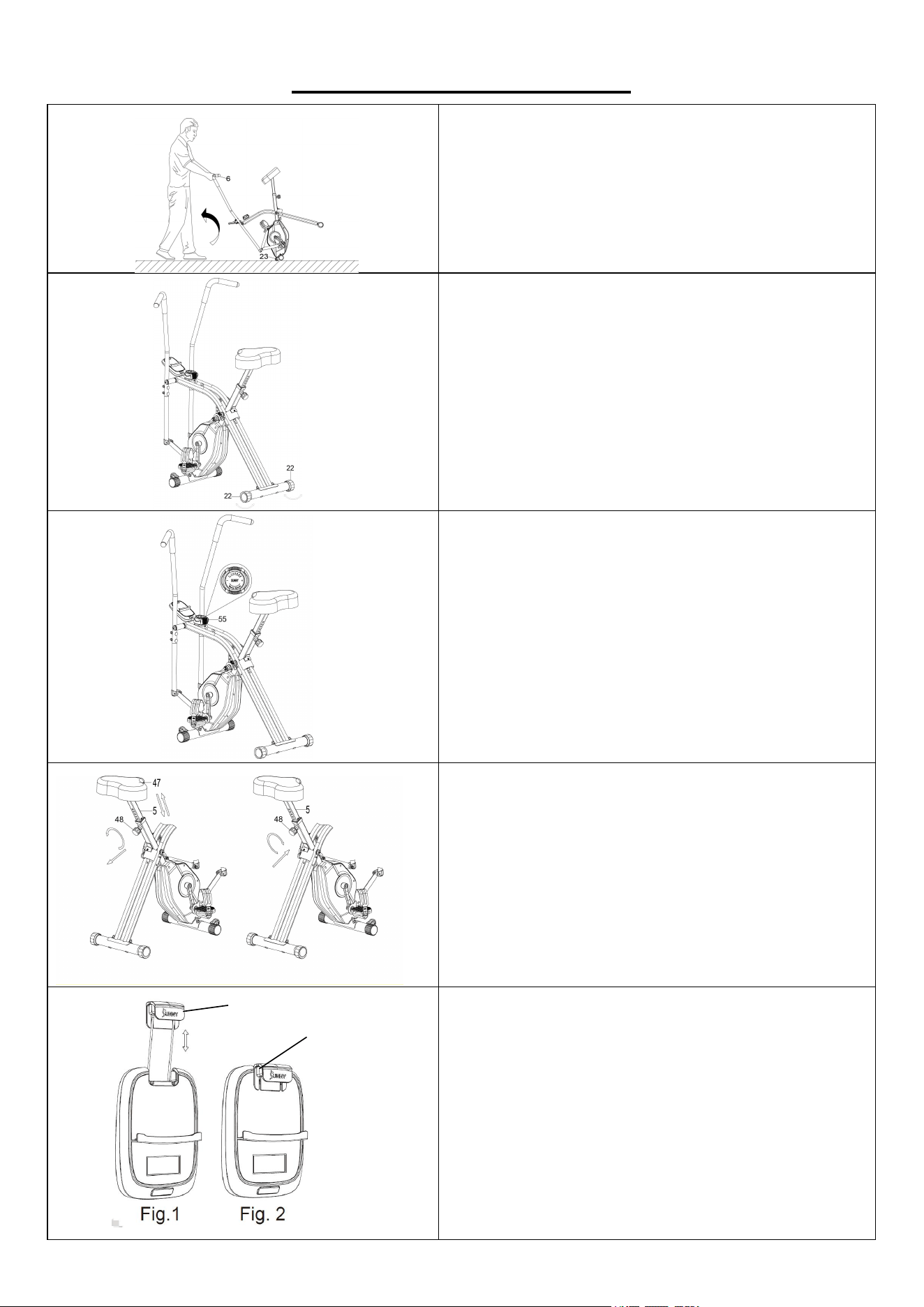
ADJUSTMENTS GUIDE
MOVING THE RECUMBENT BIKE
Hold the Left Handlebar (No. 6) and tilt the bike
until the 2 Transportation Wheels (No. 23) touch
the ground. Now you can transport the bike to the
desired location with ease.
ADJUSTING THE BALANCE
In order to achieve a smooth and comfortable ride,
you must ensure that the bike is stable and
secured. If you notice that the bike is unstable
during use, you should adjust the Rear Stabilizer
End Caps (No. 22) until the bike becomes levelled
with the floor surface.
ADJUSTING THE TENSION
Adjust the tension by rotating the Tension Control
Knob (No. 55) clockwise to increase the level of
resistance. Rotate the Tension Control Knob (No.
55) counter-clockwise to decrease the level of
resistance.
Tension levels are set at Level 1 being the lowest
and Level 14 being the highest.
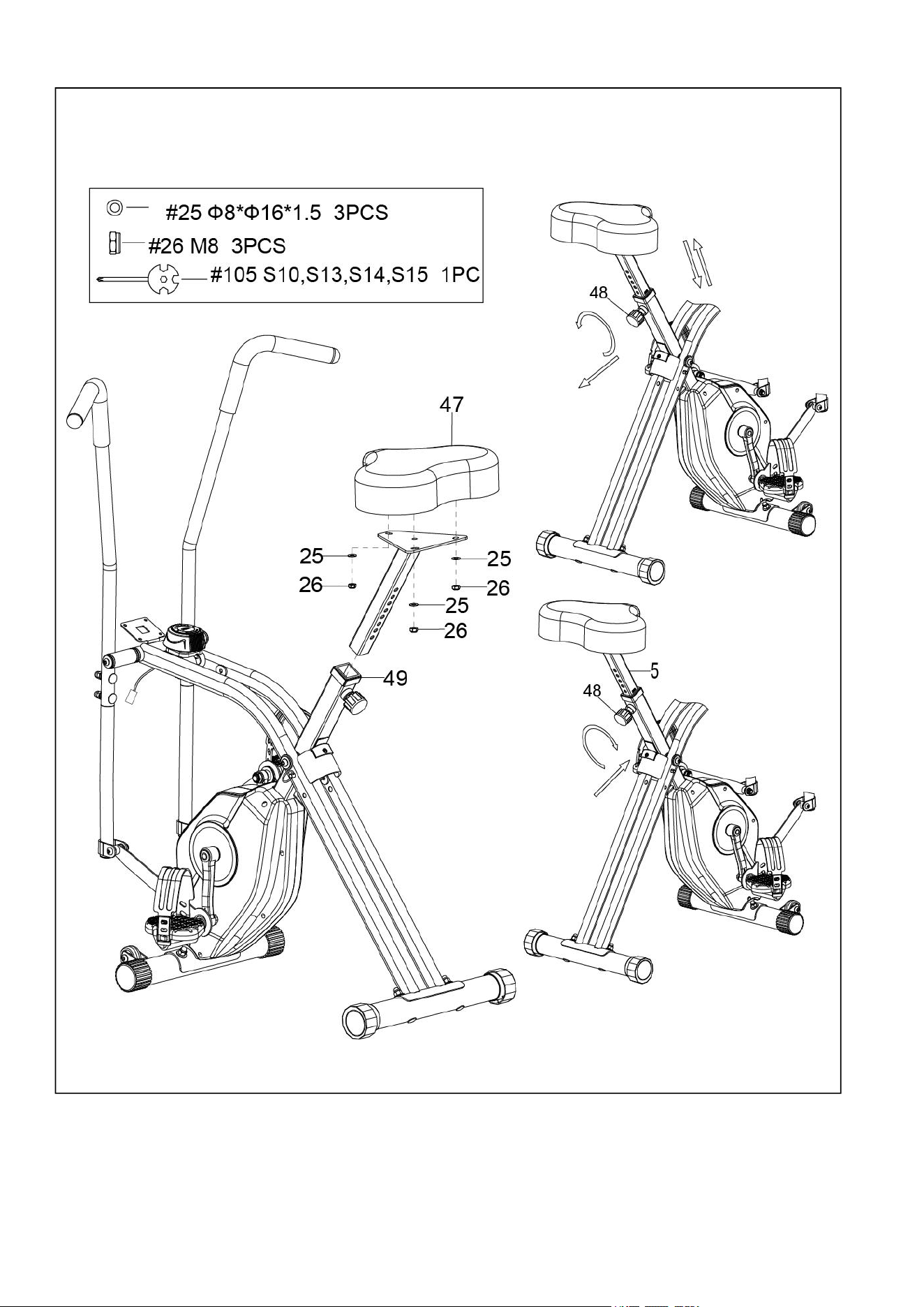
ADJUSTING THE SEAT
Loosen and pull out the Spring Pin Knob (No. 48)
to adjust the height of the Seat (No. 47). When
adjusting, you will see a limit on the Seat Support
Post (No. 5). DO NOT lift the posts passed this
mark. Always check the Spring Pin Knob (No. 48)
and to ensure that they are fully secured when you
finish making an adjustment.
The SUNNY insert (No. A) can be pulled upward to secure
the mobile device in place (as shown in Fig. 1). When the
mobile device is placed horizontally, please move the
SUNNY insert (No. A) in front of the meter after it is pulled
out (as shown in Fig. 2) to avoid the insert from returning
back into the meter.
A
A
12
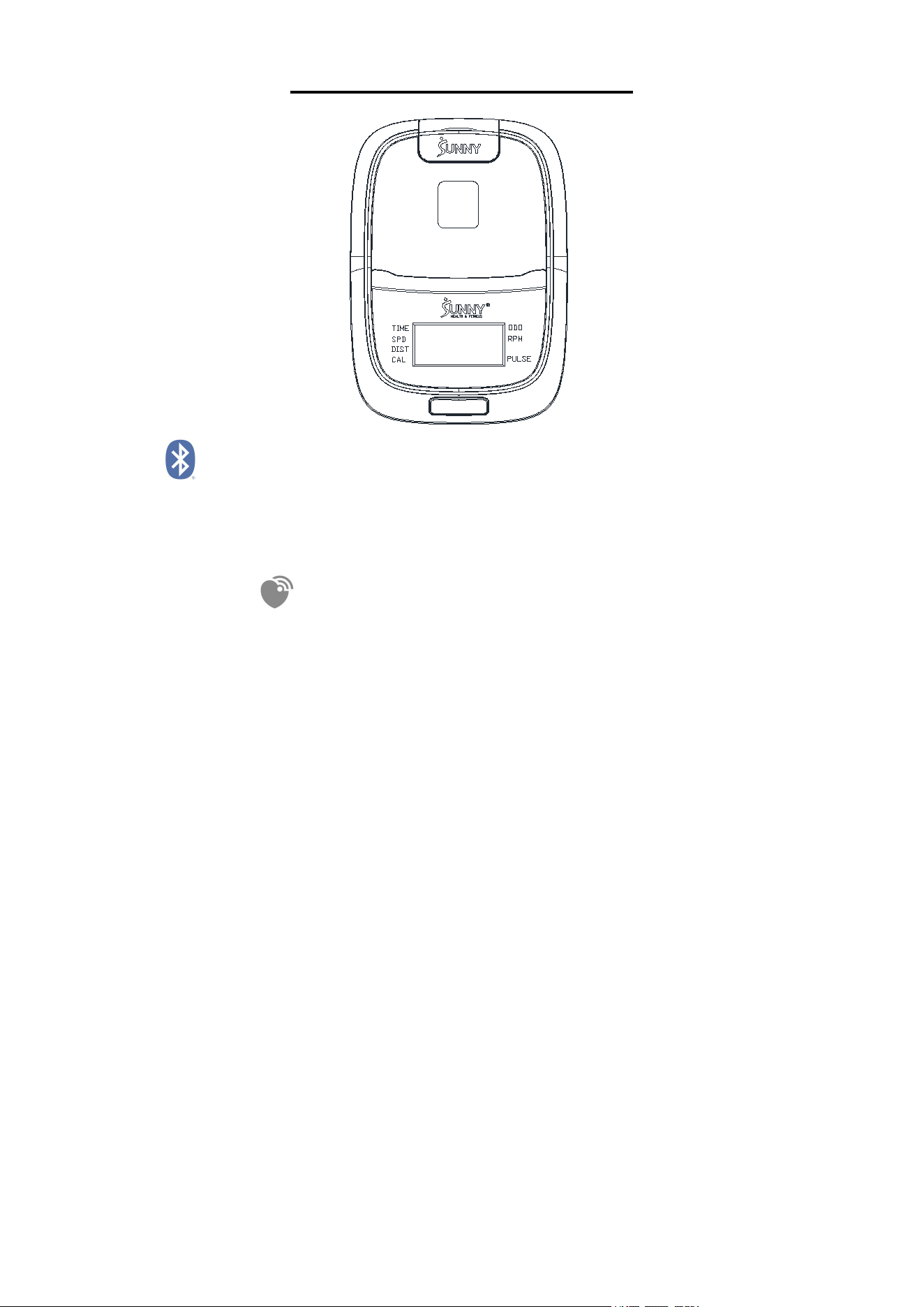
EXERCISE COMPUTER
BLUETOOTH :
1. The Bluetooth icon will flash when the computer is on or wakes from sleep mode. If no Bluetooth connection is
established within 3 minutes, the Bluetooth icon will turn off.
2. The Bluetooth icon will stay on when it is connected.
WIRELESS HEART RATE
1. The wireless heart rate icon will flash when the computer is on. If the heart rate monitor is not connected within
1 minute, the wireless heart rate icon will turn off.
2. After exercise resumes, the wireless heart rate icon will flash. If the heart rate monitor is not connected within 1
minute, the wireless heart rate icon will turn off.
3. When the computer wakes from sleep mode, the wireless heart rate icon will flash. If the heart rate monitor is
not connected within 1 minute, the wireless heart rate icon will turn off.
4. The wireless heart rate icon will flash when the MODE key is pressed. If the heart rate monitor is not connected
within 1 minute, the wireless heart rate icon will turn off.
5. The wireless heart rate icon will stay on when the heart rate monitor is connected.
NOTE: The heart rate monitor is not included. Wireless heart rate function works with SunnyFit Heart Rate
Monitor HR200. HR200 can only connect to the computer when the wireless heart rate icon is flashing.
FUNCTION BUTTON
MODE
Press the button to switch display or automatically display through each function value in sequence every 6
seconds.
Hold the MODE key for 2 seconds to reset all values except ODO when Bluetooth is not connected.
Press and hold the MODE key for 6 seconds to disconnect from both the SunnyFit APP and the heart rate monitor;
then, the computer will enter sleep mode.
OPERATION
1.POWER ON
Installs 2 pieces of 1.5V AAA batteries. (Whenever batteries are removed, all the functions values will be reset to
zero.)
2.1 WAKE UP
After entering speed signal, each function will skip to display. STOP will be displayed once no speed signal
detected for 10 seconds.
2.2 SLEEP MODE
The computer will shut off automatically and disconnect the heart rate monitor if there is no activity for 4 minutes
when Bluetooth is not connected.
13
3.SCAN
After power on or press the mode button, automatically scan through each function value in sequence every 6
seconds. SCAN-->TIME-->SPD-- > DIST-- >CAL-->ODO--> RPM-->PULSE--> SCAN
4.TIME
Accumulates total training time from 00:00 up to 999:59.
5.SPD
Display current training speed from 0.00 up to 9999.9 M/H
6.CAL
Accumulates calories consumption during training from 0.0 up to 9999.9 kcal
Note: This data is a rough guide for comparison of different exercise sessions which can not be used in medical
treatment.
7.ODO
Track the total distance traveled since battery installation from 0.00 up to 9999.9 Mile.
8.DIST
Displays the current movement distance of the user, with the display range of 0.00 to 9999.9 Mile.
9. RPM
Revolution(s) Per Minute
10. PULSE (Needs to pair with the Bluetooth device)
Display the user's heart rate from 30-240 upon pulse signal detected with pulse symbol flashing. The pulse
graphic will not flashing upon no pulse signal detected. and when there is no heart rate, “P” is displayed.
NOTE:
1. If the computer displays abnormally, please re-install the battery and try again.
2. Battery Spec: 1.5V or AAA (2PCS).
3. The batteries must be removed from the appliance before it is scrapped and that they are disposed of safely.
TECHNICAL DATA
Connectivity: Bluetooth LE
Frequency Range: 2400~2483.5Mhz
Transmitting Power: 0dBm
APP CONNECTION:
CONNECT SMART EQUIPMENT TO SUNNYFIT APP:
1. Scan to download SunnyFit from the app store.
2. Ensure that the Bluetooth function is turned on from your mobile device.
3. If this is your first time using the SunnyFit app, follow the in-app instructions to register for your free SunnyFit
account and log in.
4. Begin any workout activity that matches your smart equipment, then follow the onscreen prompts to search
for and connect to your smart equipment.
5. When connected, your stats and records will be displayed at the end of your course/session, and recorded in
your account profile!
TROUBLESHOOTING:
If you are having trouble connecting your smart equipment, visit www.sunnyfit.com/guide or scan the QR
code below:
If you require additional support, please contact support@sunnyfit.com.

14
TROUBLESHOOTING
PROBLEM
SOLUTION
There is no display on the computer.
1. Remove the computer and verify that the
wire from the computer is properly
connected to the wire that comes from the
front post.
2. Check if the batteries are correctly
positioned and battery springs are in proper
contact with batteries.
3. The batteries in the computer may be
unresponsive. Change to new batteries.
The bike wobbles when in use.
Turn the adjustable end caps on the front and
rear stabilizers as needed to level the bike.
The bike makes squeaking noise when in
use.
Some bolts on the bike might have become
loose. Please inspect all the bolts and tighten
any loose bolts.
CLEANING
The bike can be cleaned with a soft, clean, damp cloth. Do not use abrasives or solvents on plastic
parts. Please wipe your perspiration off the recumbent bike after each use. Be careful not to get
excessive moisture on the computer display panel as this might cause electrical hazard or
electronics to fail. Please keep the bike, especially the computer, out of direct sunlight to prevent
screen damage. Please inspect all assembly bolts and pedals on the recumbent bike for proper
tightness every week.
STORAGE
Store the recumbent bike in a clean and dry environment, away from children.
15
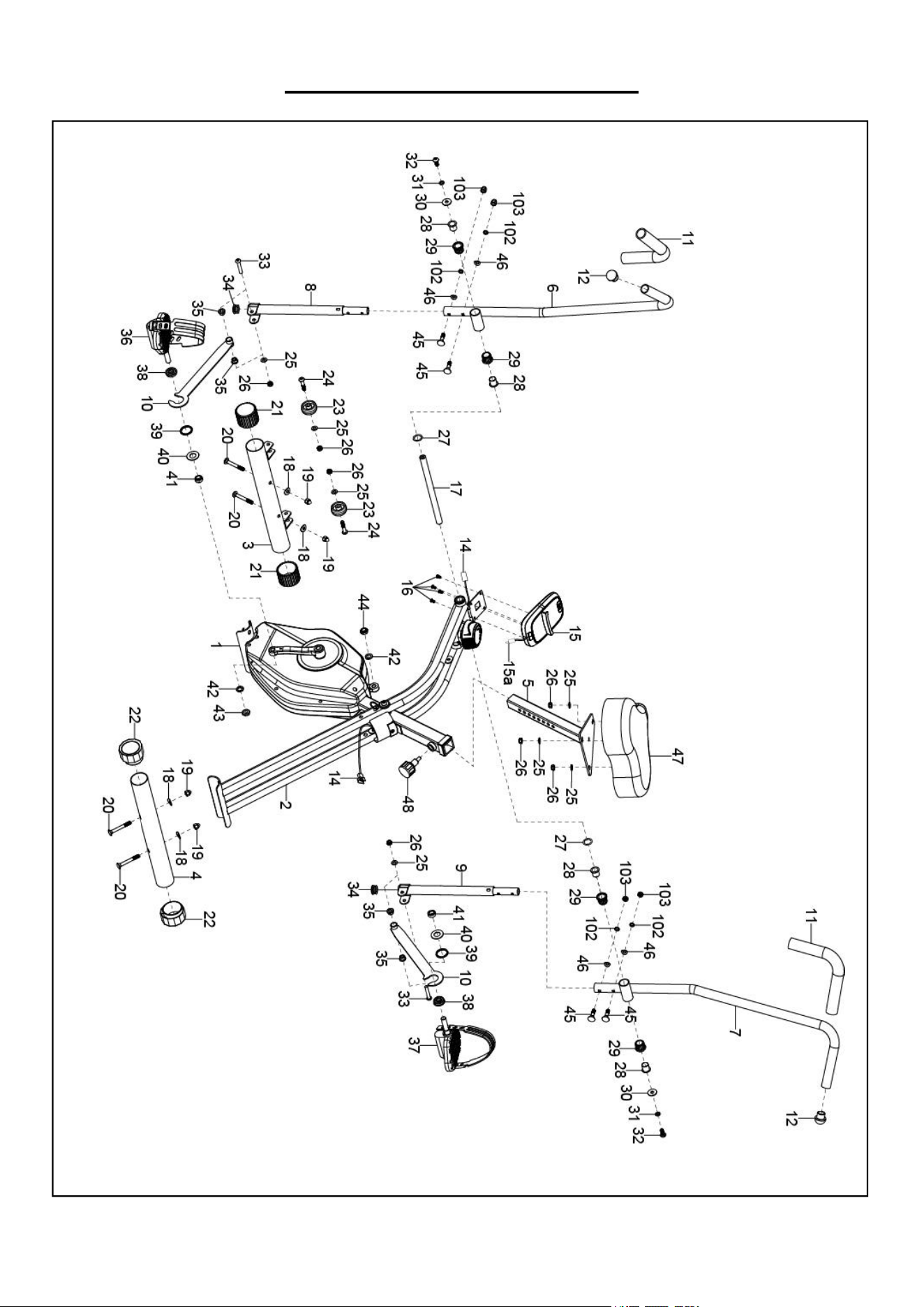
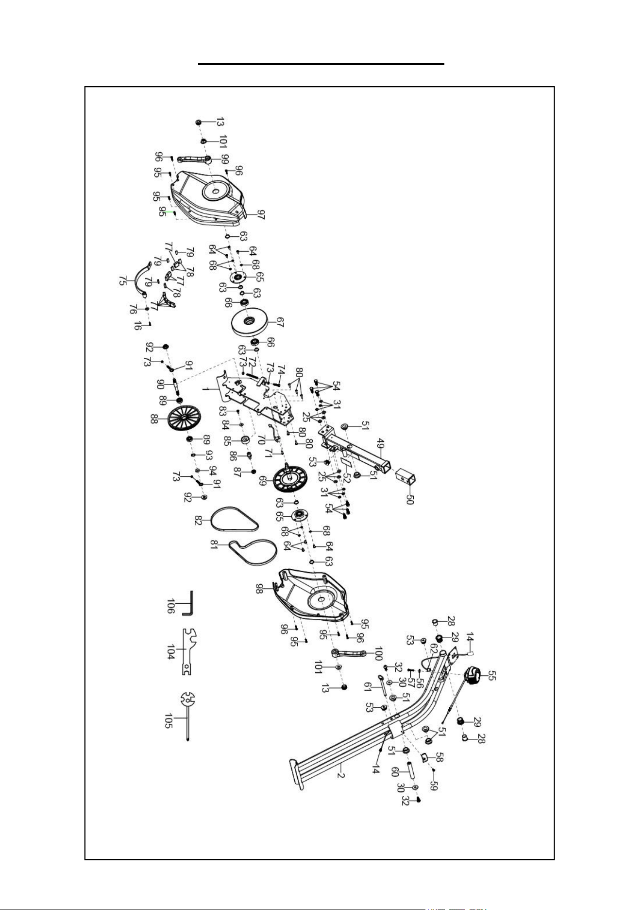
EXPLODED DIAGRAM 1
16
EXPLODED DIAGRAM 2

17
PARTS LIST
No.
Description
Spec.
Qty
No.
Description
Spec.
Qty
1
Front Main Frame
Post
1
31
Spring Washer
Φ8
12
2
Rear Support Frame
1
32
Bolt
M8*20
4
3
Front Stabilizer
1
33
Bolt
M8*45
2
4
Rear Stabilizer
1
34
Cap
2
5
Seat Support Post
1
35
Sleeve
Φ18*Φ8*10
4
6
Left Handlebar
1
36
Left Pedal
1
7
Right Handlebar
1
37
Right Pedal
1
8
Left Swing Tube
1
38
Single Thrust Bearing
2
9
Right Swing Tube
1
39
Spacer
Φ38*28.6*34
2
10
Connecting Rod
2
40
Big Flat Washer
Φ17.5*Φ34*3.0
2
11
Front Handlebar
Foam Grip
Φ24*Φ30*310
2
41
Sleeve
Φ21*8
2
12
Round Cap
Φ25*1.5
2
42
Spring Washer
Φ20*Φ13
2
13
Hand Pulse Sensor
with Wire
2
43
Left Nylon Nut
B1/2”*20
1
14
Computer Wire II
L=950mm
1
44
Right Pedal Bolt
B1/2”*20
1
15
Computer
1
45
Bolt
M6*35
4
15
Computer Wire A
1
46
Curve Washer
Φ6*Φ16*1.5
4
16
Pan Screw
M5*10
5
47
Seat
1
17
Pendulum axis
1
48
Spring Pin Knob
M16*1.5
1
18
Big Curve Washer
Φ8*Φ20*2.0
4
49
Seat Post
1
19
Nut
M8
4
50
Bushing
1
20
Bolt
M8*60
4
51
Plastic Shaft Sleeve
6
21
Cap
Φ50*1.5
2
52
PC Pad
60*31*0.3
1
22
Rear Stabilizer End
Cap
2
53
Wire Plug II
20*15
3
23
Transportation
Wheel
Φ42*Φ8.2*22
2
54
Screw
M8*20
6
24
Bolt
M8*40
2
55
Tension Control Knob
L=1150mm
1
25
Washer
Ф8*Ф16*1.5
13
56
Big Flat Washer
Φ5*Φ15*1.0
1
26
Nut
M8
11
57
Bolt
M5*25
1
27
Wave Washer
Φ16*Φ21*0.3
2
58
Seat Support Block
1
28
Sleeve
Φ23.5*20
6
59
Screw
M5*8
1
29
Plastic Shaft Sleeve
Φ28.6*21
6
60
Mandrel
1
30
Big Flat Washer
Φ8*Φ25*2.0
4
61
Ring Spring Pin
Φ8*108
1

18
PARTS LIST
No.
Description
Spec.
Qty
No.
Description
Spec.
Qty
62
Wire Plug I
Φ12.1
1
84
Big Flat Washer
Φ20*Φ8*2.0
1
63
Shaft Circlip
Φ17
6
85
Bearing
1
64
Bolt
M6*10
6
86
Pulley Shaft
1
65
Plastic Bearing Seat
2
87
Nut
M10
1
66
Bearing
6003ZZ
2
88
Driven Plate
1
67
Flywheel
1
89
Bearing
6000
2
68
Washer
Φ6*Φ12*1.0
6
90
Driven Shaft
1
69
Belt Pully Crank
1
91
Pulling Bol
M6*45
2
70
Sensor Wire
L=250mm
1
92
Nut
M10*1.0
2
71
Bolt
M4*10
1
93
Shaft Circlip
Φ10
1
72
Spring
1
94
Nut
M10*1*3
1
73
Nut
M6
4
95
Screw
ST4.2*25
6
74
Bolt
M6*2
1
96
Screw
ST4.2*15
4
75
Magnetic Plate Post
1
97
Left Cover
1
76
Washer
Φ5*Φ12*1.0
1
98
Right Cover
1
77
Magnet
20*20*8
8
99
Left crank
1
78
Square Magnet
20*10*5
3
100
Right crank
1
79
Magnet Plate
3
101
Nut
M10*1.25
2
80
Bolt
M5*15
5
102
Spring Washer
Φ6
4
81
Belt
240 PJ4
1
103
Nut
M6
4
82
Belt
230 PJ3
1
104
Spanner
S10-13-17-19
1
83
Screw
M5*10
1
105
Spanner
S10-13-14-15
1
84
Big Flat Washer
Φ20*Φ8*2.0
1
106
Allen Wrench
S6
2
Version 1.0

19