Loading ...
Loading ...
Loading ...
4. CONTROLS (CONT’D)
4.3 MAIN WALL CONTROL INSTALLATION (CONT’D)
4.4 WALL CONTROL(S) CONNECTION TO THE UNIT
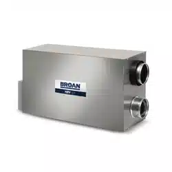
Splice back the end of the cable to access the 4 wires. Strip the end of each wire. Connect
each wire to its corresponding terminal: YELLOW wire to “Y’’, RED wire to “R’’, GREEN
wire to “G’’ and BLACK wire to “B’’. See illustration at right.
Reinstall the front module onto the back plate and tighten the locking screw.
Y
B
G
R
YELLOW wire
RED wire
BLACK wire
GREEN wire
VE0271A
15
VE0273
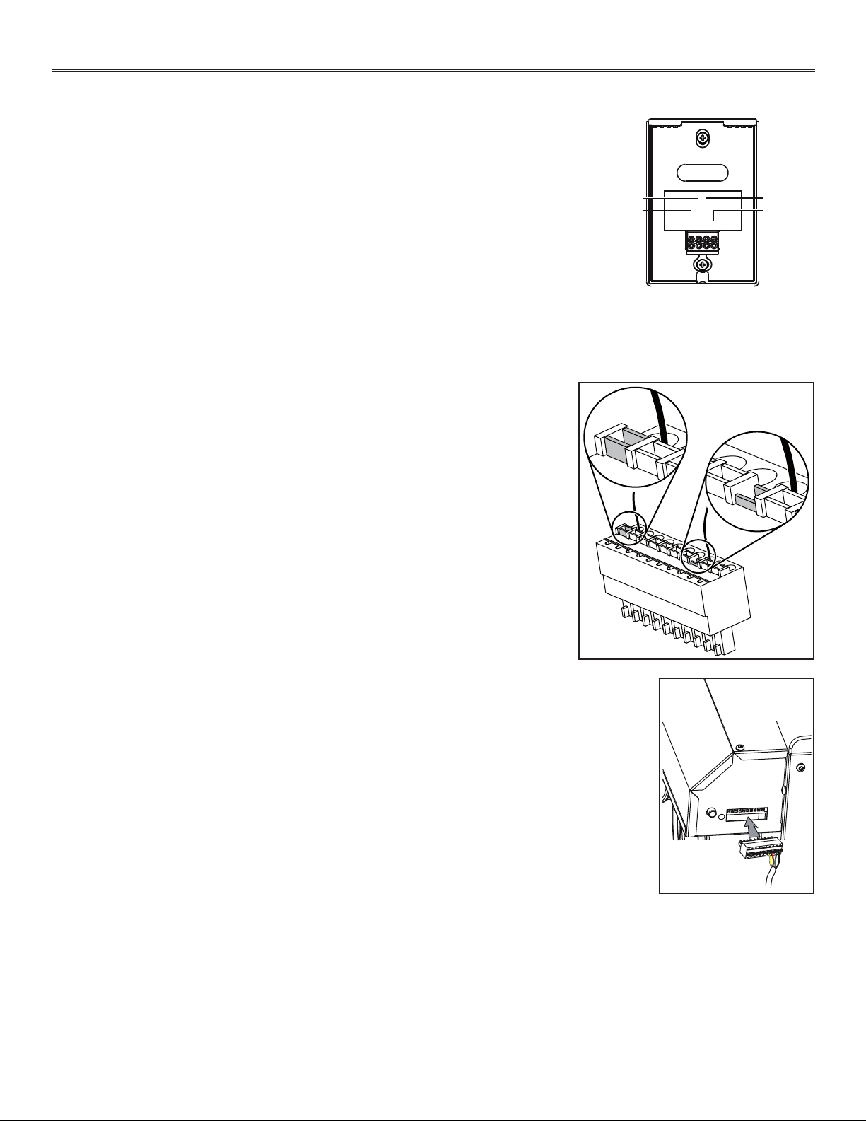
Once the control(s) connections have been made, insert the terminal connector in the electrical
compartment interface. Plug the unit.
Use the terminal connector included in the installation kit to perform the electrical connection
for main and optional wall controls. Check if all wires are correctly inserted in their
corresponding holes in the terminal block. (A wire is correctly inserted when its orange
receptacle is lower than another one without wire. On illustration at right, wire A is
correctly inserted, but not wire B.)
Splice back the end of the cable to access the 4 wires. Strip the end of each wire. Connect
each wire to its corresponding terminal: YELLOW wire to “Y’’, RED wire to “R’’, GREEN wire
to “G’’ and BLACK wire to “B’’. Check if all wires are correctly inserted in their corresponding
holes in the terminal block.
Connect the auxiliary control cable, if installed (not shown).
VE0272
A
B
Loading ...
Loading ...
Loading ...