C R D 5
I I I I I Ill
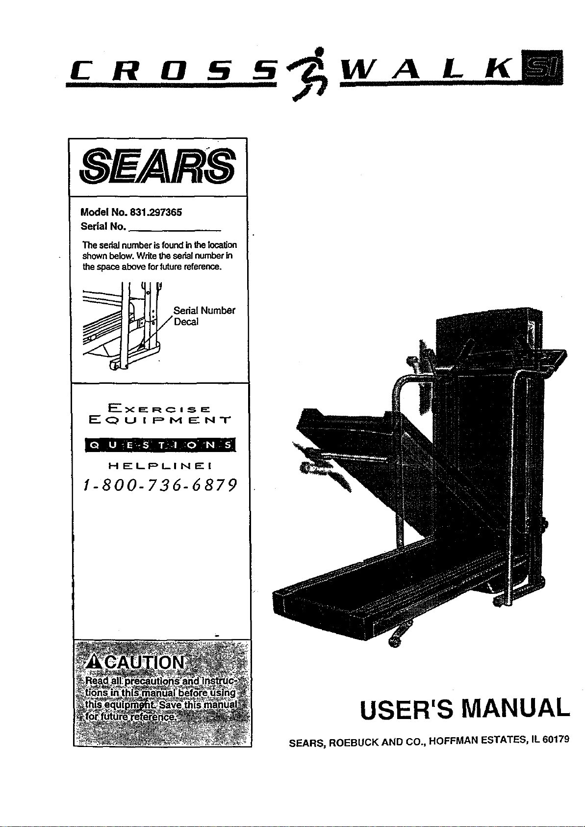
Model No. 831.297365
Serial No.
The serialnumberisfoundintheincalJon
shownbelow.Writetheserialnumberin
thespaceaboveforfuturereference.
i_-j. Se_a,Num_
• -__/Decal
J
J
F-_<:IE£ RC I S F="
I:" (:_ U I p M E NT
HELPLIN£1
1-800-736-6879
USER'S MANUAL
SEARS, ROEBUCK AND CO., HOFFMAN ESTATES, IL 60179
TABLE OF CONTENTS
IMPORTANT PRECAUTIONS ............................................ . . . . .. .
BEFORE YOU BEGIN .........................................................
ASSEMBLY .................................................................
OPERATION AND ADJUSTMENT ...............................................
HOW TO FOLD AND MOVE THE TREADMILL .....................................
TROUBLE-SHOOTING .......................... : ........ .....................
O,gQI_eI.Q'O" "2
°O_,o,O,Ooeaal7
............. 10
............. 12
CONDITIONING GUIDELINES o............o .. . .'. ......................................... . .. 14
ORDERING REPLACEMENT PARTS ......................................... . .. ... . .. Back Cover
FULL 90 DAY WARRANTY ................................................... ..... . .. Back Cover
Note: A HARDWARE-IDENTIFICATION CHART, an EXPLODED DRAWING, and a PART LIST and are attached
to the center of thls manual. Please save them for futurereference.
IMPORTANT PRECAUTIONS
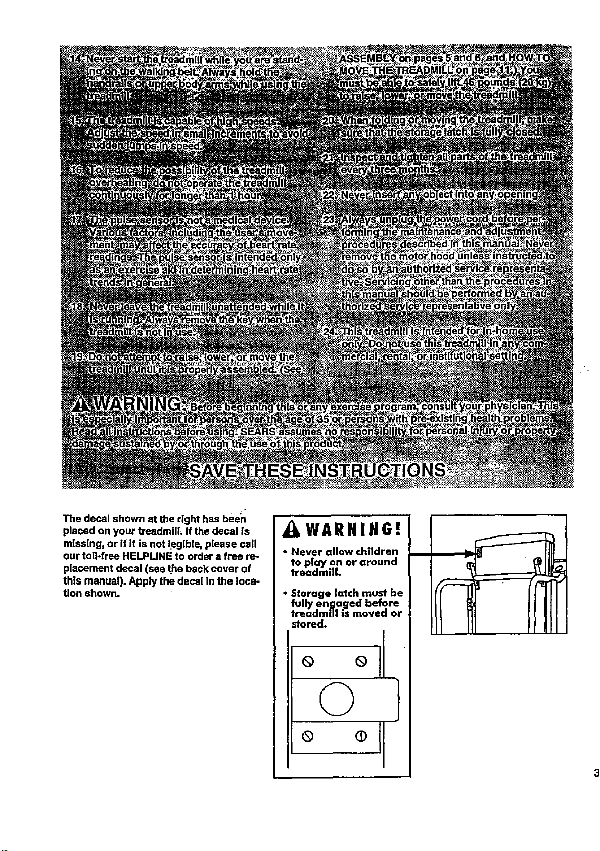
The decal shown at the right has been
placed on your treadmill, If the decal Is
mlsslng, or if it is not legible, please call
our toll-free HELPLINE to order a free re-
placement decal (see the back cover of
this manual). Apply the decal in the loca-
tion shown.
LWARNIHG!
• Never allow children
to play on or around
treadmill.
• Storage latch must be
fully engaged before
treadmill is moved or
stored.
° °11
BEFORE YOU BEGIN
Thank you for selecting the PROFORM =CROSS-
WALK SI treadmill. The CROSSWALK SI treadmill
blends advanced technology with Innovative design to
let you enjoy an excellent form of can:r_ovascularexer-
rise In the convenience and pdva.cyof your home.
For your benefit, read this _tanual carefully before
using the treadmill. Ifyou have additional questions,
please call our toll-free HELPLINE at 1-800-736-6879,
Monday through Saturday, 7 a.m. until 7 p.m. Central
Time (excluding holidays). To help us assist you,
please note the productmodel number and serial num-
ber before calling. The model number of the treadmill
Is 831.297365. The sedal number can be found on a
decal attached tothe treadmill (see the front cover of
this manual for the location).
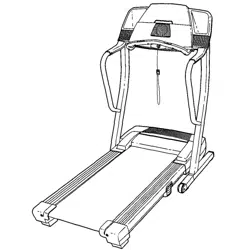
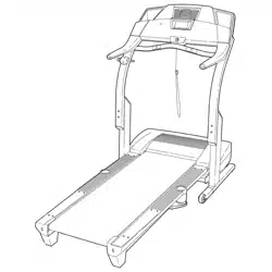
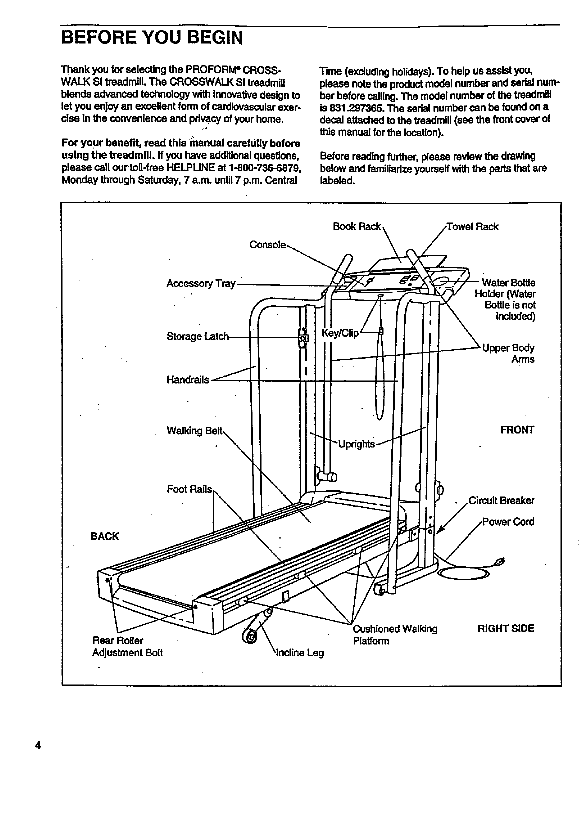
Before reading further, please review the drawing
below and familladze yourself with the parts that are
labeled.
Handrails
Foot Rails
BACK
Rear Roller
Adjustment Bolt
Book Rack Towel Rack
y/Clip_
)
Platform
Holder (Water
Bottle isnot
ir udod)
Upper Body
Arms
FRONT
Circuit Breaker
RIGHT SIDE
4
i
ASSEMBLY
CAUTION: Read and follow step I below before removing the restraining fie (see drawing 1). If the restrain.
Ing tie is removed prematurely, sedous bodily Injury may result. Assembly requires two people. Set the tread-
millIn a cleared area and remove the packing materials except for the restraining fie. Do not dispose of the
packing materials unblassembly Iscompleted. Use the HARDWARE IDENTIRCATION CHART in the center of
thIs manual to identify the parts used in assembly. Assembly requires the Included allen wrench L=_, a
phillips serewddver .=====.[_), and two adjustable wrenches Q:::::==_.
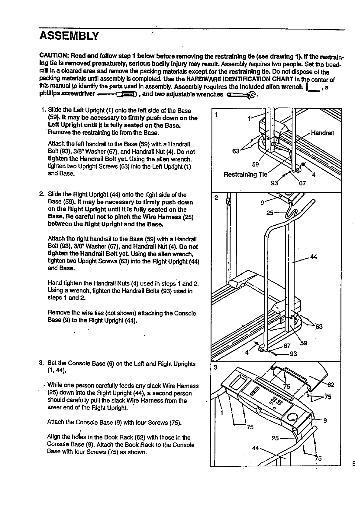
1. Slide the Left Upright (1) onto the left side of the Base
(59). It may be necessary to firmly push down on the
Left Updght until It is fully seated on the Base.
•Remove the restraining tie from the Base.
Attach the lefthandrail to the Base (59) with a Handrail
Bait (93), 3/8" Washer (67), and Handrail Nut (4). Do not
tighten the Handrail Bolt yeL Using the allen wrench,
tightentwo Upright Screws (63) intothe Left Upright(1)
and Base.
2. Slide the Right Upright (44) onto the dght side ofthe
Base (59). It may be necessary to firmly push down
on the Right Updght until It is fully seated on the
Base. Be careful not to pinch the Wire Harness (25)
between the Right Updght and the Base.
Attach the dght handrail to the Base (59) with a Handrail
Bolt (93), 3/8" Washer (67), and Handrail Nut (4). Do not
tighten the Handrail Bolt yet. Using the allen wrench,
tighten two Updght Screws (63) into the Right Updght (44)
and Base.
Hand tighten the Handrail Nuts (4) used in steps 1 and 2.
Using a wrench, tighten the Handrail Bolts (93) used in
steps 1 and 2.
Remove the wire ties (notshown) attaching the Console
Base (9) to the Right Updght (44).
3. Set the Console Base (9) on the Left and Right Uprights
(t, 44).
• While one person carefullyfeeds any slack Wire Harness
(25) down intothe Right Upright (44), a second person
shouldcarefully pullthe slack Wire Hamees from the
lower end of the Right Upright.
Attach the Console Base (9) with four Screws (75).
Alignthe hd_esin the Book Rack (62) with those inthe
Console Base (9). Attach the Book Rack to the Console
Base with four Screws (75) as shown.
1
59
Restraining
9
67
75
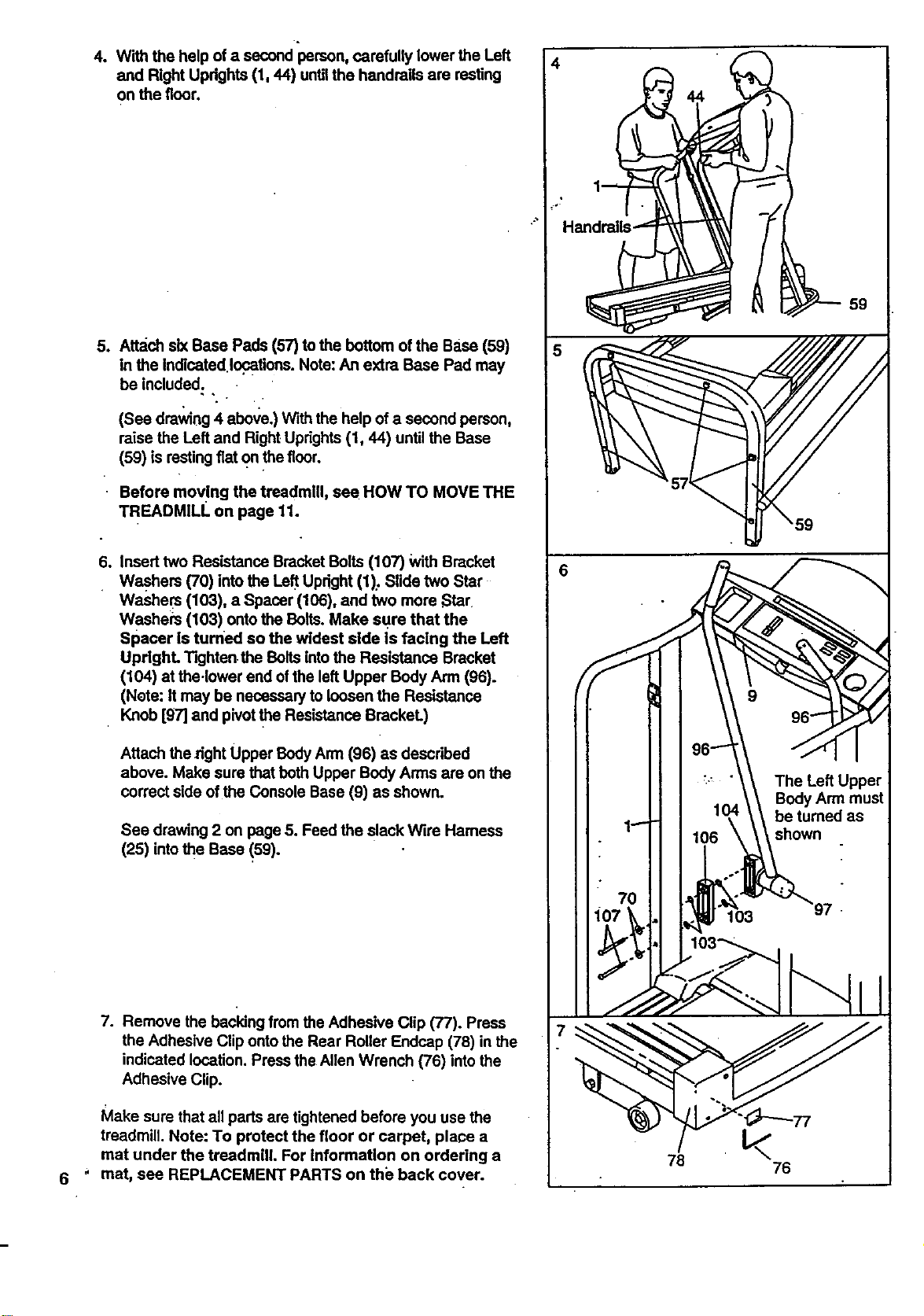
4. With the help of a second person, carefully lower the Left
and Right Updghts (1, 44) untilthe handrails are resting
on the floor.
5o
Attach six Base Pads (57) to the bottom of the Base (59)
in the Indicated locations. Note:An extra Base Pad may
be included.
(See drawing 4 above.) With the help of a second person,
raise the Left and Right Uprights(1, 44) until the Base
(59) is restingfiat on thefloor.
Before moving the treadmill, sea HOW TO MOVE THE
TREADMILL on page 11.
So
Insert two Resistance Bracket Bolts (107) WithBracket
Washers (70) into the Left Upright (1): Slide two Star
Washers (103), a Spacer (106), and two more Star
Washers (103) ontothe Bolts. Make sure that the
Spacer is turned so the widest side is facing the Left
UpdghL Tighten.the Bolts into the Resistance Bracket
(104) at the.lower end of the left Upper Body Arm (96).
(Note: It may be necessary to loosen the Resistance
Knob [g7] and pivotthe Resistance BrackeL)
Attach the _ght Upper BodyArm (96) as described
above. Make sure that both Upper Body Arms are on the
correct side ofthe Console Base (9) as shown.
See drawing 2 on page 5. Feed the slack Wire Hamess
(25) intothe Base (59).
7. Remove the backing from the Adhesive Clip (77). Press
the Adhesive Clip onto the Rear Roller Endcap (78) in the
indicated location. Press the Allen Wrench (76) into the
Adhesive Clip.
Make sure that all pads are tightened before you use the
treadmill. Note: To protect the floor or carpet, place a
mat under the treadmill. For Information on ordering a
mat, see REPLACEMENT PARTS on the back cover.
4
7
76
76
OPERATION AND ADJUSTMENT
THE PERFORMANT LUBE TM WALKING BELT
Your treadmill features a walking belt coated with
PERFORMANT LUBETM, a high-performance lubricant.
IMPORTANT: Never apply silicone spray or other
substances to the walldng belt or the walking plat-
form. They will deteriorate the walking belt and
cause excessive wear.
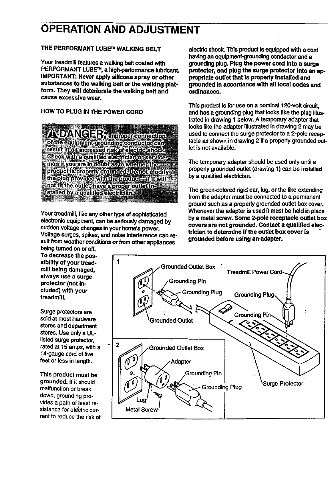
HOW TO PLUG IN THE POWER CORD
electric shock. This product is equipped with a cord
having an equipment-grounding conductor and a
grounding plug. Plug the power cord Into a surge
protector, and plug the surge protector Into an ap-
propriate outlet that Is properly Installed and
grounded In accordance with all local codes and
ordinances.
This product is for use on a nominal 120-volt circuit,
and has a grounding plug that looks like the plug illus-
trated In drawing I below. A temporary adapter that
looks IRe the adapter illustrated in drawing 2 may be
used to connect the surge protectorto a 2-pois recep-
tacle as shown in drawing 2 if a propedy grounded out-
let is not available.
The temporary adapter should be used only until a
properly grounded outlet (drawing 1) can be installed
by a qualified electrician.
Your treadmill, like any other type of sophisticated
electronic equipment, can be seriouslydamaged by
sudden voltage changes in your home's power.
Voltage surges, spikes, and noise interference can re-
sult from weather conditions or from other appliances
being tumed on or off.
To decrease the pos-
sibltity of your tread- 1
mill being damaged,
always use a surge
protector (not in-
cluded) with your
treadmill.
Surge protectors are
sold at most hardware
stores and department
stores. Use only a UL-
listed surge protector,
rated at 15 amps, with a
14-gauge cord offive
feet or less in length.
This product must be
grounded. If it should
malfunction or break
down, groundingpro-
vides a path of least re-
sistance for electriccur-
rent to reduce the riskof
The green-colored dgid ear, lug, or the like extending
from the adapter must be connected to a permanent
ground such as a properly grounded outlet box cover.
Whenever the adapter is used It must be held in place
by a metal screw. Some 2-pole receptacle outlet box
covers are not grounded. Contact a qualified elec-
trician to determine if the outlet box cover is
grounded before using an-adapter.
/Grounded Outlet Box
• /Grounding Pin
.._unding Plug
_Grounded Outlet
__-.1_ /GrounGroundedOutlet Box
Adapter
ding Pin
Plug
Protector
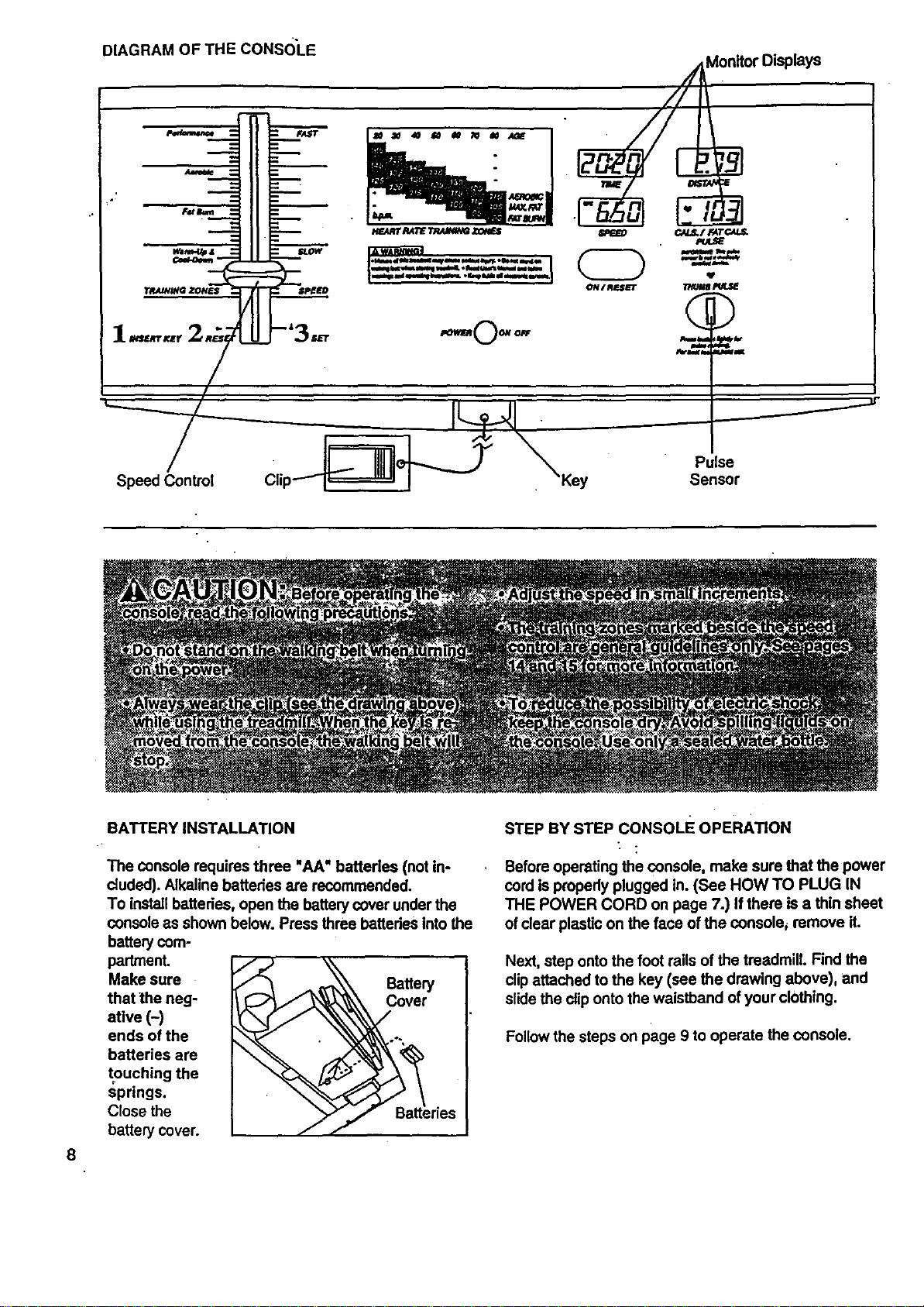
DIAGRAMOFTHECONSOLE
///_on_or Displays
]12 I
J
IIE I- -'=BB.,_ I B601I_";D_
1.,... 2_;_ .o--0-o- ~.%__.
8
BATTERY INSTALLATION
The console requires three "AA" batteries (not in-
cluded). Alkaline batteries are recommended.
To install batteries, open the battery cover under the
console as shown below. Press three batteries Into the
battery com-
partment.
Make sure Battery
that the neg- Cover
atlve (-)
ends of the
batteries are
touching the
springs.
Close the
battery cover.
STEP BY STEP CONsoLE OPERATION
Before operating the console, make sure that the power
cord is prepedy plugged in. (See HOW TO PLUG IN
THE POWER CORD on page 7.) If there is a thin sheet
of clear plastic on the face of the console_ remove it.
Next, step onto the foot rails of the treadmill. Find the
clipattached to the key (see the drawing above), and
slidethe cliponto the waistband of your clothing.
Follow the steps on page 9 to operate the console.
B
B
B
B
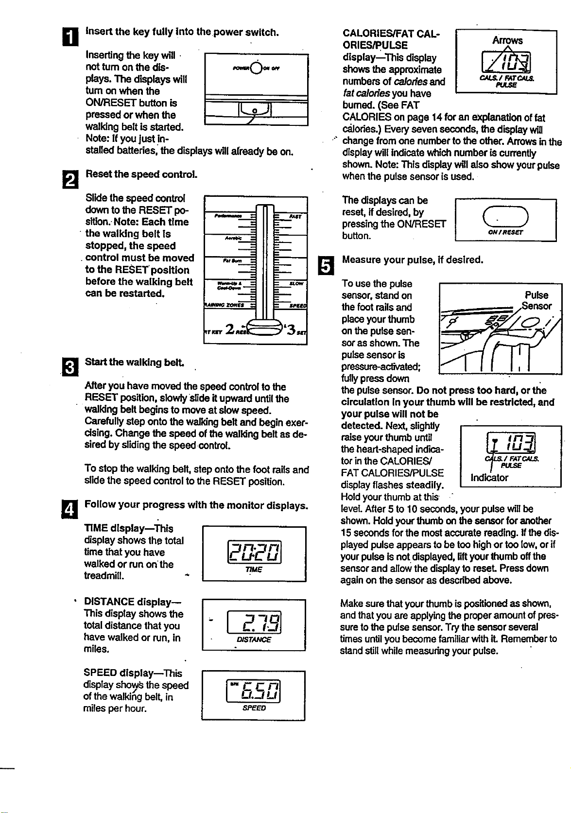
Insert the key tully into the power switch.
Inserting the key will.
not tum on the dis- "="O" _"
plays. The displays will
turn on when the
ON/RESET button is
pressed or when the
walldng belt is started.
Note: If you just in-
stalled battedes, the displays w,I already be on.
Reset the speed control.
Slide the speed control
down to the RESET po-
slllon. Note: Each time
• the walking belt is
stopped, the speed
control must be moved
to the RESET position
before the walking belt
can be restarted.
Start the walking bell
After you have moved the speed control to the
RESET position, slowly Slide it upward until the
walking bell begins to move at slow speed.
Carefully step onto the walking belt and begin exer-
cising. Change the speed of the walking belt as de-
sired by sliding the speed control.
To stop the walking belt, step onto the foot roils and
slide the speed control to the RESET position.
Follow your progress with the monitor displays.
TIME display--'i'his
display shows the total
time that you have
walked or run on the
treadmill.
[2n. rll
u- -Ul
T/ME
I
DISTANCE display--
This display shows the
total distance that you
have walked or run, in
miles.
-{ zT l
D/STANCE
I
SPEED display--This
display sho_ysthe speed
of the walkihg belt, in
miles per hour.
-FCnl
L-L-JLq
,SPEED
B
ORIES/PULSE Arrows
display--This display
shows the approximate
numbers of calories and c.N._/ FATCAL_
PU_E
fat calories you have
burned. (See FAT
CALORIES on page 14 for an explanation of fat
calories.) Every seven seconds, the display will
change from one number to the other. Arrowsinthe
display will indicate which number is currently
shown. Note: This display will also show your pulse
when the pulse sensor is used.
The displays can be I
reset, if desired, by
pressingthe ON/RESET
button. ON/nes_r
Measure your pulse, if desired.
To use the pulse
sensor, stand on Pulse
the foot roilsand
place your thumb
on the pulse sen-
sor as shown. The
pulse sensor is
pressure-activated;
fullypress down
the pulse sensor. Do not press too hard, or _e
circulation in your thumb will be restricted, and
your pulse will not be
detected. Next, slightly
raise your thumb until
F.
the heart-shaped indice-
tor inthe CALORIES/ c_/FATC._
FAT CALORIES/PULSE Indicator
/-
display flashes steadily.
Hold your thumb at this "
level.After 5 to 10 seconds, your pulse willbe
shown. Hold yourthumb on the sensor for another
15 seconds for the mostaccurate reading. Ifthe dis-
played pulse appears to be too high or too low,or if
your pulse is not displayed, liftyour thumb offthe
sensor and allow the display to reseL Press down
again on the sensor as described above.
Make sure that your thumb is positionedas shown,
and that you are applying the proper amount ofpres-
sure tothe pulse sensor. Try the sensor several
times untilyou become familiar with it. Remember to
stand stillwhile measuring your pulse.
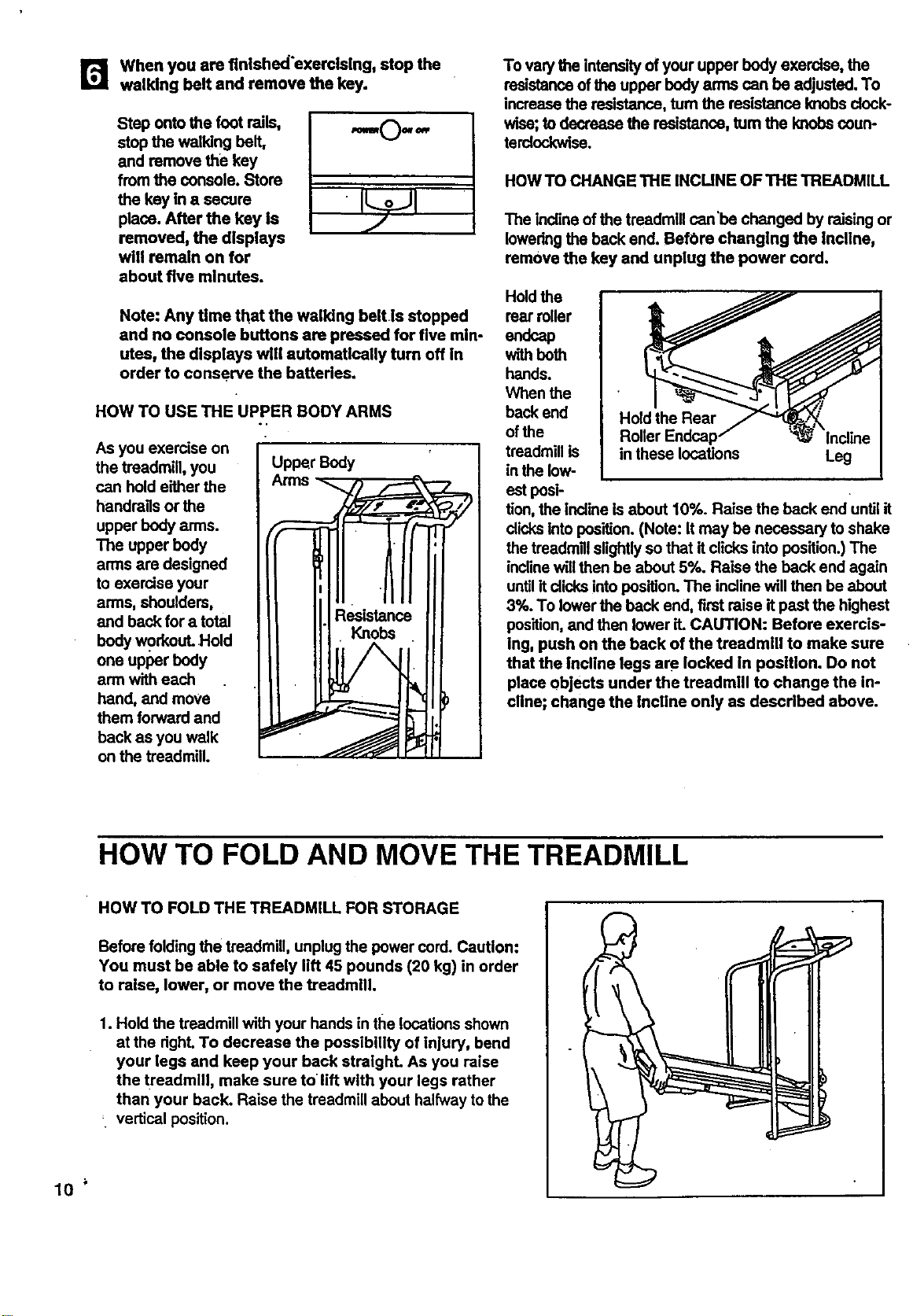
r_ when you are finished'exercising, stop the
walking belt and remove the key.
Step onto the foot rails,
stop the walking belt,
and remove the key
from the console. Store
the key in a secure
place. After the key is
removed, the displays
will remain on for
about five minutes.
,I.0.-,
•
Note: Any time that the walking belt is stopped
and no console buttons are pressed for five min-
utes, the displays will automatically turn off in
order to conserve the batteries.
HOW TO USE THE UPPER BODY ARMS
As you exercise on
the treadmill, you
can hold either the
handrags or the
upper body arms.
The upper body
arms are designed
to exercise your
arms, shoulders,
and back for a total
body workout. •Hold
one upper body
arm with each
hand, and move
them forward and
back as you walk
on the treadmill.
Upper Body
To varythe intensity of your upper body exercise, the
resistance of the upper body arms can be adjusted. To
increase the resistance, turn the resistance knobs dock-
wise;to decrease the resistance, turn the knobscoun-
terclockwise.
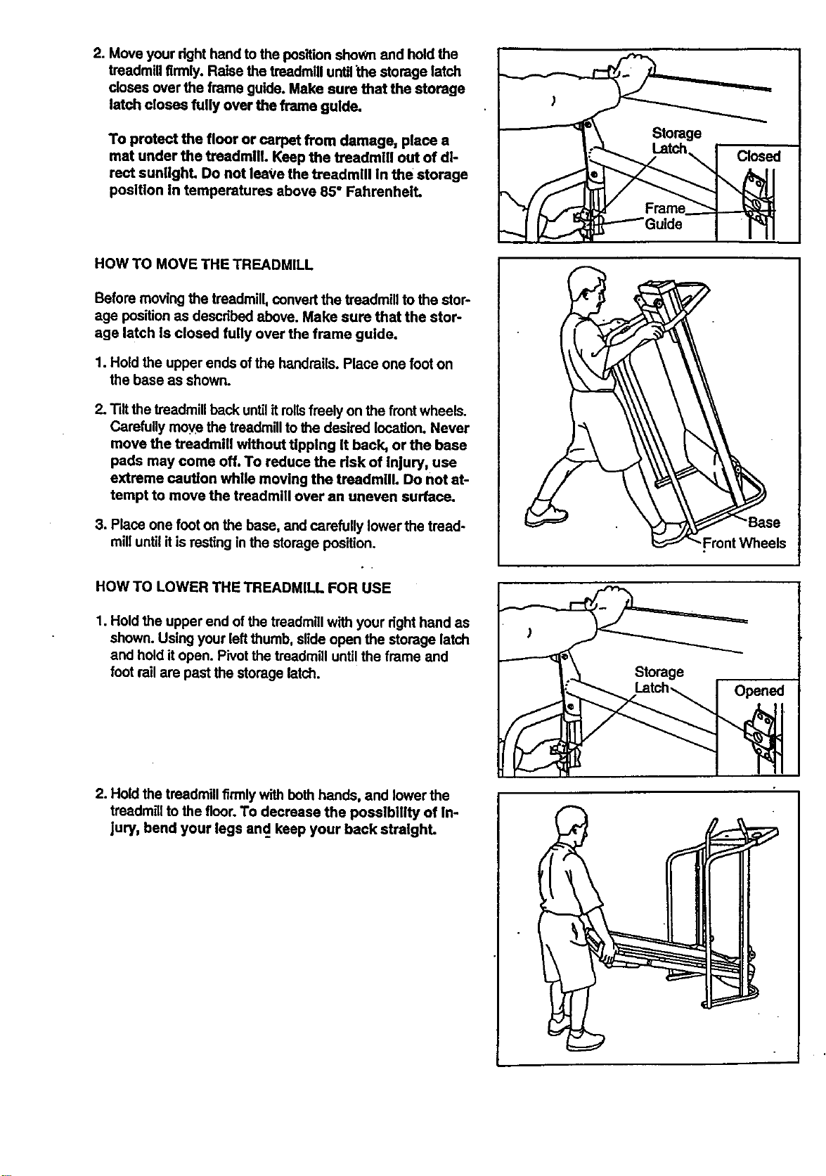
HOW TO CHANGE THE INCUNE OF THE TREADMILL
The Inclineof the treadmill can'be changed by raising or
lowering the back end. BefOre changing the incline,
remove the key and unplug the power cord.
Hold the
rear miler
endcap
with beth
hands.
When the
back end
of the
treadmill is
inthe low-
Hold the Rear
in these locations
Leg
est pesi-
tion, the incline is about 10%. Raise the back end until it
dicks into position.(Note: It may be necessary to shake
the treedmlilslightlyso that it clicks into position.) The
inclinewillthen be about 5%. Raise the back end again
untilit dicks into position.The incline will then be about
3%. To lower the back end, first raise it past the highest
position,and then lower it. CAUTION: Before exercls-
ing, push on the back of the treadmill to make sure
that the Incline legs are locked in position. Do not
place objects under the treadmill to change the in-
cline; change the incline only as described above.
HOW TO FOLD AND MOVE THE TREADMILL
HOW TO FOLD THE TREADMILL FOR STORAGE
Before folding the treadmill, unplug the power cord. Caution:
You must be able to safely lift 45 pounds (20 kg) in order
to raise, lower, or move the treadmill.
1. Hold the treadmill with your hands in the locationsshown
at the dght. To decrease the possibility of injury, bend
your legs and keep your back straight. As you raise
the tz'eadmlll, make sure tolift with your legs rather
than your back. Raise the treadmill about halfway to the
_ vertical position.
10
2. Move your right hand to the position shoWn and hold the
treadmill firmly. Raise the treadmill untilthe storage latch
doses over the frame guide. Make sure that the storage
latch closes fully over the frame guide.
To protect the floor or carpet from damage, place a
mat under the treadmill. Keep the treadmill out of di-
rect sunlight. Do not leave the treadmill in the storage
position In temperatures above 85° Fahrenheit.
HOW TO MOVE THE TREADMILL
Before moving the treadmill, convert the treadmill to the stor-
age position as descdbed above. Make sure that the stor-
age latch Is closed fully over the frame guide.
1. Hold the upper ends ofthe handrails. Place one foot on
the base as shown.
2. Tilt the treadmill back untilit rollsfreely on the frontwheels.
Carefully move the treadmillto the desired location. Never
move the treadmill without tipping It back, or the base
pads may come off. To reduce the risk of inlury, use
extreme caution while moving the treadmill. Do not at-
tempt to move the treadmill over an uneven surface.
3. Place one foot on the base, and carefully lower the tread-
mill untilit is resting in the storage position.
HOW TO LOWER THE TREADMILL FOR USE
1. Hold the upper end of the treadmill with your dght hand as
shown. Using your left thumb, slide open the storage latch
and hold itopen. Pivot the treadmill until the frame and
foot rail are past the storage latch.
"-Front Wheels
Storage
2. Hold the treadmill firmly with both hands, and lower the
treadmill to the floor.1"odecrease the posstbillty of In-
jury, bend your legs and. keep your back stralghL
I
1
TROUBLE-SHOOTING
12
Most treadmill problems can be solved by fullowing the simple steps below. Rnd the symptom that alP
plies, and follow the steps listed. If further assistance Is needed, call our toll-frea HELPLINE at 1-800-736-
6879, Monday through Saturday, 7 a.m. until 7 p.m. Central Time (excluding holidays).
1. SYMPTOM: THE POWER DOES NOT TURN ON
a. Make sure that the power cord is plugged intoa surge protector, and that the surge protector is plugged into
a pmpedy grounded outieL (Sea HOW TO PLUG IN THE POWER CORD on page 7.) Use only a UL-ilsted
surge protector, rated at 15 stops, with a 14-gauge cord of five feet or less in length.
b. After the power cord has been plugged in, make sure that the key is fully inserted into the console. (Sea step
1 on page 9.)
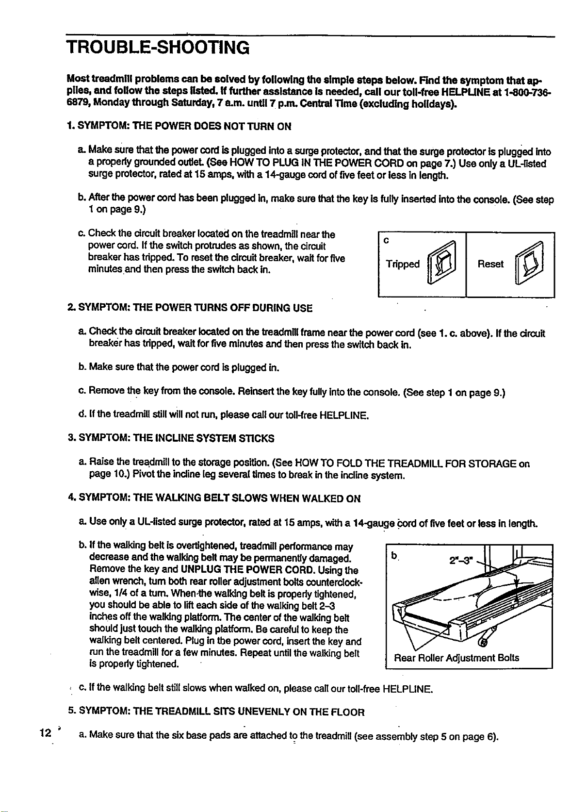
c. Check the circuit breaker located on the treadmill near the
power curd. If the switch protrudes as shown, the circuit
breaker has tripped. To reset the circuit breaker, wait for five
minutesand then press the switch back in.
c
Tdpped Reset
2. SYMPTOM: THE POWER TURNS OFF DURING USE
a. Check the circuit breaker located on the treadmillframe near the power cord (see 1. c. above). If the circuit
breaker has tripped, wait for five minutes and then press the switch back in.
b. Make sure that the power cord is plugged in.
c. Remove the key from the console. Reinsert the key fullyintothe console. (See step 1 on page 9.)
d. If the treadmill stillwill not run, please call our toil-free HELPLINE.
3. SYMPTOM: THE INCUNE SYSTEM STICKS
a. Raise the trea.dmiilto the storage position. (See HOW TO FOLD THE TREADMILL FOR STORAGE on
page 10.) Pivot the incline leg several times to break in the incline system.
4. SYMPTOM: THE WALKING BELT SLOWS WHEN WALKED ON
a. Use only a UL-listed surge protector, rated at 15 stops, with a 14-gauge _ord of five feet or less in length.
b,
If the walking belt isovertightened, treadmill performance may
decrease and the walking belt may be permanently damaged.
Remove the key and UNPLUG THE POWER CORD. Using the
alien wrench, turn both rear rolleradjustment boltscounterclock-
wise, 1/4 of a turn. When-the walking belt is properly tightened,
you should be able to lifteach side of the walking belt 2-3
inches off the walking platform.The center of the walking belt
shouldjust touch the walking platform. Be careful to keep the
walking belt centered. Plug in the power cord, insertthe key and
run the treadmill for a few minutes. Repeat untilthe walking belt
is propedy tightened.
Rear Roller Adjustment Bolts
, c. If the walking belt stillslows when walked on, please call our toll-free HELPUNE.
5. SYMPTOM: THE TREADMILL SITS UNEVENLY ON THE FLOOR
a. Make sure that the six base pads are attached to the treadmill (see assembly step 5 on page 6).
6.SYMPTOM:THEWALKINGBELTISOFF-CENTERWHENWALKEDON
a.Ifthewalkingbelthasshiftedtothe left, first remove the key and
UNPLUG THE POWER CORD. Using the 3/16, end ofthe allen
wrench, turn the left rear rolleradjustment bolt _, and
the right bolt counterdockwlse, 1/4 of a tum each. Be careful not
to overtighten the walking bell Plug in the power cord, Insert the
key and run the treadmill for a few minutes. Repeat untilthe
walking belt is centered•
b. If the walking belt has shifted to the dght, first remove the key
and UNPLUG THE POWER CORD. Using the 3/16" end of the
allen wrench, turn the leftroar rolleradjustment bolt counter-
clockwise, and the dght boltclockwise, 1/4 of a turn each. Be
careful not to overtightenthe walking belt. Plug In the power
cord, insert the key and runthe treadmill for a few minutes.
Repeat until the walking belt is centered.
c. If the walking belt slipswhen walked on, first remove the key
and UNPLUG THE POWER CORD. Using the 3/16" end of the
alien wrench, tum both roar roller adjustment bolts dockwise_
1/4 of a turn. When the walkingbelt is correctly tightened, you
should be able to lifteach side of the walking belt 2-3 inches off
the walking platform.The center of the walking belt should just
touch the walking platform.Be careful to keep the walking belt
centered. Plug in the power cord, insert the key and run the
treadmill for a few minutes. Repeat until the walking belt is prop-
edy tightened.
a
b
C
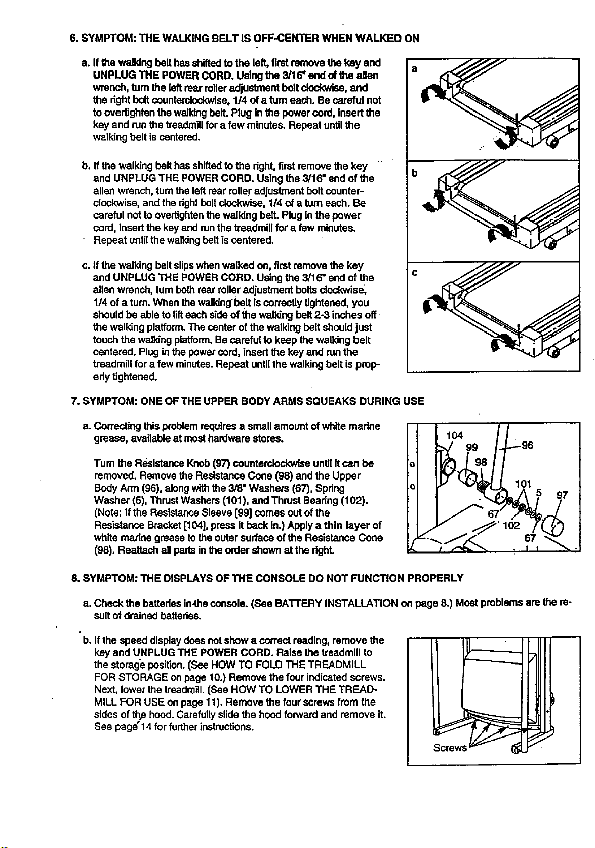
7oSYMPTOM: ONE OF THE UPPER BODY ARMS SQUEAKS DURING USE
a. Correcting this problem requires a small amount ofwhite madne
grease, available at most hardware stores.
Tum the Re.sistanceKnob (97) counterclockwise until it can be
removed• Remove the Resistance Cone (98) and the Upper
Body Arm (96), along with the 3/6, Washers (67), Spdng
Washer (5), Thrust Washers (101), and Thrust Beadng (102).
(Note: If the Resistance Sleeve [99] comes out of the
Resistance Bracket [104], press it back in.) Apply a thin layer of
white marine grease tothe outer surface of the Resistance Cone-
(98). Reattach all pads in the order shown at the dghL
104
99
8. SYMPTOM: THE DISPLAYS OF THE CONSOLE DO NOT FUNCTION PROPERLY
a• Check the batteries in.the console. (See BATTERY INSTALLATION on page 8.) Most problems are the re-
sult of drained batteries.
• b. If the speed display does not show a correct reading, remove the
key and UNPLUG THE POWER CORD. Raise the treadmill to
the storage position.(See HOW TO FOLD THE TREADMILL
FOR STORAGE on page 10.) Remove the four indicated screws.
Next, lower the treadmill. (See HOW TO LOWER THE TREAD-
MILL FOR USE on page 11). Remove the four screws from the
sides of tl_ hood. Carefully slide the hood forward and remove it.
See page"14 for further instructions.
Screws
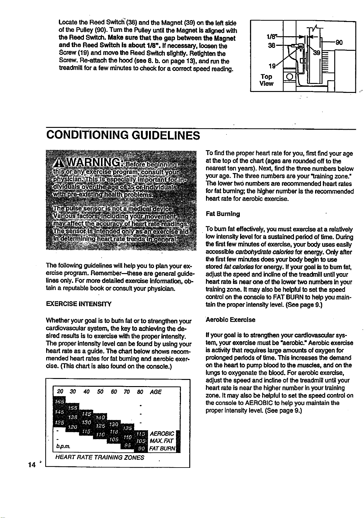
Locate the Reed Switch'(38) and the Magnet (39) on the left side
of the Pulley (90). Tum the Pulley until the Magnet is aligned with
the Reed Switch. Make sure that the gap between the Magnet
and the Reed Switch Is about 1/8". If necessary, loosen the
Screw (19) and move the Reed Switch slightly. Refighten the
Screw. Re-attach the hood (see 8. b. on page 13), and runthe
treadmill for a few minutes to check for a correct speed reading.
1/_'_
38-- "r_
I/
19/ ===
Top
View
CONDITIONING GUIDELINES
The following guidelines will helpyou to plan your ex-
ercise program. Remember--these are general guide-
lines only. For more detailed exercise Information, ob-
fain a reputable book or consult your physician.
EXERCISE INTENSITY
Whether your goal is to burn fat or to strengthen your
cardiovascular system, the key toachieving the de-
sired results is to exercise with the proper intensity.
The proper intensity level can be found by using your
heart rate as a guide. The chart below shows recom-
mended heart rates for fat burningand aerobic exer-
cise. (This chart is also found on the console.)
2O 30 40 50 60 70 8O
AGE
AEROBIC
MAX.FAT
FATBURN
To findthe proper heart rate for you, firstfind your age
at the top of the chart (ages are rounded offto the
nearest ten years). Next, findthe three numbers below
yourage. The three numbers are your "training zone."
The lowertwo numbers are recommended heart rates
forfat buming; the higher number isthe recommended
heart rate for aerobic exercise.
FatBuming
• To bum fat effectively, you must exercise at a relatively
low intensitylevel for a sustained period of time. During
the first few minutes of exercise, your bodyuses easily
accessible carbohydrate calories fol"energy. Only after
the firstfew minutes does your body begin to use
stored fat calories for energy. Ifyour goal isto bum fat,
adjustthe speed and inclineof the treadmill untilyour
heart rate isnear one of the lower two numbers in your
training zone. It may also be helpfulto set the speed
control on the console to FAT BURN to help you main-
rain the proper intensity level. (See page 9.)
Aerobic Exercise
Ifyour goal is to strengthen your cardiovascular sys-
tem, your exercise must be "aerobic."Aerobic exercise
is activity that requires large amounts of oxygen for
prolonged pededs of time. This increases the demand
on the head to pump blood to the muscles, and on the
lungsto oxygenate the blood. For aerobic exercise,
adjustthe speed and inclineof the treadmill until your
heart rate is near the higher number in your training
zone. It may also be helpfulto set the speed controlon
the console to AEROBIC to help you maintain the
properintensity level. (See page 9.)
b.p.m.
HEART RATE TRAINING ZONES
14
HighPerformanceAthleticConditioning
Ifyourgoalishighperformanceathleticconditioning,
setthe speed control on the console to PERFOR-
MANCE to help you maintain the proper intensity level.
(See page 9.) Note: Dudng the first few weeks of your
exercise program, keep your heart rate near the low
end of your training zone.
HOW TO MEASURE YOUR HEART RATE
To measure your heart rate, use the pulse sensor on
the console. (See page 9.) If your head rate is too high
or too low, adjust the speed or incline of the treadmill
until your head rate is at the proper level.
WORKOUT GUIDELINES
Each workout should include three important pads:
A Warm-up
Begin with5 to 10 minutes of stretching and light exer-
cise. Warming up increases the bodytempamtum, head
rate, and cimulation in preparation for vigorous exercise.
Training Zone Exercise
After warming up, increase the intensity of your exer-
clse untilyour heart rate Is In your trainlng zone for 20
to 60 minutes. (Dudng the firstfew weeks of your exer-
cise program, do not keep your heart rata in your train-
Ing zone for longer than 20 minutes.) Breathe regularly
and deeply as you exercise--never hold your breath.
A Cool-down
Rnish each workout with 5 to 10 minutes ofstretching
to cool down. This will increase the flexibility ofyour
mu_es and will help toprevent post-exercise problems.
Exercise Frequency
To maintain or improve your condition, complete throe
workouts each week, with at least one day of restbe-
tween workouts. After a few months, you may com-
plete up to five workouts each week.
Remember, the key to success is to make exercise a
regular and enjoyable part of your everyday life.
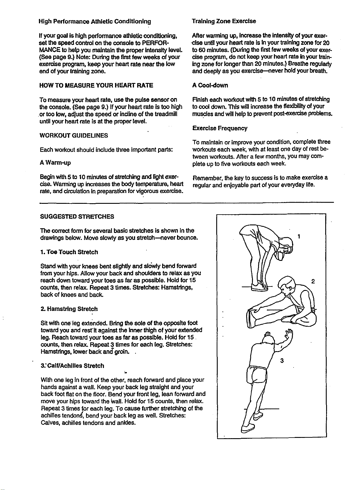
SUGGESTED STRETCHES
The co_ect form for several basic stretches is shown in the
drawings below. Move slowly as you stretch--never bounce.
1. Toe Touch Stretch
Standwith your knees bent slightly and sk_wiybend forward
from your hips. Allow your back and shoulders to relax as you
reach down toward your toes as faras possible. Hold for 15
counts, then relax. Repeat 3 times. Stretches: Hamstrings,
back of knees and back.
2. Hamstring Stretch
Sit with one leg extended. Bdng the sole of the opposite foot
toward you and restit against the Inner thigh of your extended
leg. Reach toward your teas as far as possible. Hold for 15
counts, then relax. Repeat 3 times for each leg. Stretches:
Hamstdngs, lower back and groin..
3: Calf/Achllles Stretch
With one leg in front of the other, reach forward and place your
hands against a wall. Keep your back leg straight and your
back foot fiat on the floor. Bend your front leg, lean forward and
move your hips toward the Wall. Hold for 15 counts, then relax.
Repeat 3 times for each leg. To cause further stretching of the
achilles tendonS, bend your back leg as well. Stretches:
Calves, achilles tendons and ankles.
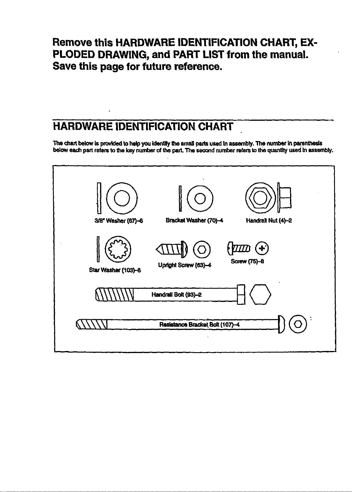
Remove this HARDWARE IDENTIFICATION CHART, EX-
PLODED DRAWING, and PART LIST from the manual.
Save this page for future reference.
HARDWARE IDENTIFICATION CHART
The chart below is providedto help you id_ the small pads used In assembly. The number in parentheds
below each part refers to the key number of the pad. The seo_nd number refers tothe quantlty used In assembly.
IG u@
washer(ST)-S BracketWasher(70)-4 HarKIra]lNut (4)-2
Upt_htScrew(s3)-4 Screw(Tspe
, t
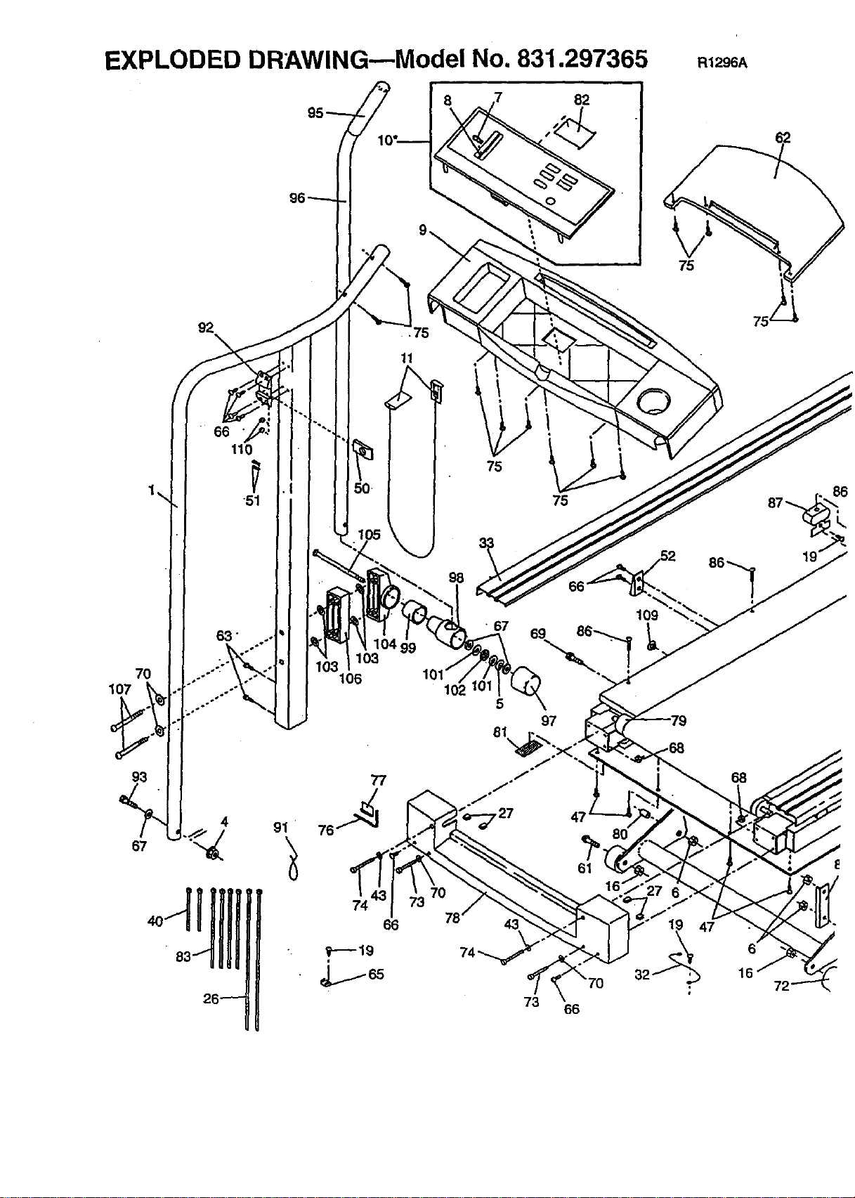
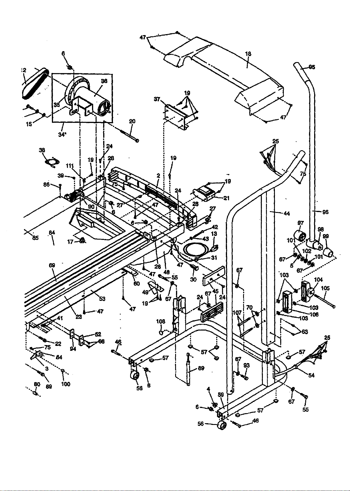
EXPLODED DRAWING--Model No. 831.297365 R1296A
8 82
62
75
70
107
93
67
92
• 66
110
"51
63"
4
91
•7,=
11
106
77
74
66
P--19
98
75
75
• 67
69
102
5
97
81
61
78 43
73 66
109
16"
"/19 47
16
!
!
28
84.
• \ 17
19
-@
108
18
25
"103
104
57 55
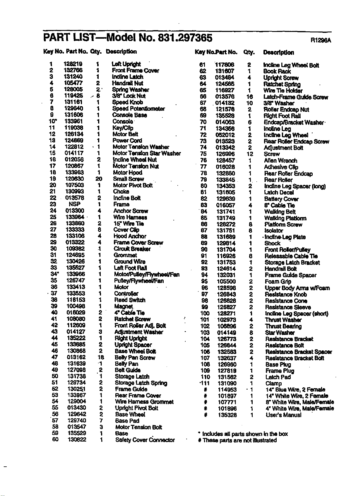
PART LiST--Model No. 831.297365
Key14o.PartNo. Qty. Oescdptlon
KeyNo.P_t No. Qty. Oe_dption
138219 LeltUt ht
132766 _ Front Frame Cover _ 117206181607 12 Inollne LegWheal Bolt
Book
131240
1O5477 12 Inc_rmLek:h
Handrail Nut 6_ 013484124585 4 Upr_lt Screw
Ratchet 8pdng
66 128oo5 _' SpringWe._er 116 WireTle Huider119425 . 3/8" Lock Nut _ 116927
013576 Latd-PFtameGuide Screw
7 131161 1 Speed Knob 67 .014132 10 3/8"Washer
3 129640 1 Speed Putengometor 68 121576 2 Roller Endoap Nut
9 131606 1 Console Base 69 135,528 1 FlightFoot Pall
10" 133961 1 Console 70 014063 6 Endcap/BracketWasher -
11 119038 1 Key/Cllp 71 134366 1 IrK_ne Leg
12 126134 1 Motor Belt 72 052012 2 IncgneLeg Whe_ "
13 124669 1 Power Cord 73 013523 2 Rear RollerEndcap Sorew
14 122812 , 1 MotorTenalon Washer 74 013342 2 AdJ_t Bolt
15 014117 1 MotorTen_rm Star Wuher 75 126996 12 Screw
16 012056 2 _.nolineWheel Nut 76 128457 1 AlienWm,'lch
17 120867 1 MotorTension Nut 77 016028 1 Adhesive Clip
18 133968 1 MotorI-Igod 78 182880 1 Rear Roller Endca.o
19 120630 20 Small Screw . 79 133845 1 Rear Roller
20 167503 1 Motor PivotBoR 90 134353 2 InollneLng Spacer (long)
21 130993 1 Choke 51 131605 1 Latch Decal
22 0135"/8 2 Incr_e Bolt 82 1296_9 1 _ttery Cover
23 NSP 1 Frame 83 016057 4 8" Cadle "l'te
24 013300 4 _ Scow ' 84 131741 1 Walking Belt
25 133964 • 1 Wire Hame_ 85 131749 1 WalldngPlatform
26 13,3860 2 1_..W'n Tie 86 128272 8 PtatformScrew
27 133_33 8 Cover CUp 67 131751 8 Isolator
28 133106 4 HoodAnchor 58 131689 1 •Ir_line.Leg Plato
29 018322 4 Frame Cover SCrew 89 129814 1 Shock
30 109_32 .1 CircuitBreaker 90 131704 1 Front Roler/PuIk)y
31 124695 1 Grommet 91 116926 8 Ralea,_ble C4zbleTie
82 130426 1 GroundWire 92 131753 1 Storage Latch Bracket
33 135527 1 Left FootReJ 93 124614 2 Handrail Bolt
34" 133968 1 Mutor/Puiley/Flywheel/FIm 94 132031 1 Frame Guide Spacer
35 126747 1 Puiley/RywheeVFan 95 105500 2 Foam Grip
36 133413 1 Motor 96 128595 2 Uppat"BodyArmsw,_-.eam
• 37 133553 1 Con_olkN' " 97 126843 2 _ Knob
38 118153 1 Reed Swlt_ 98 125828 2 ResistanceCone
39 100498 1 Magnet 99 126827 2 ResistanceSleeve
40 016029 2 4" Cabl_Tie 100 128271 1 Incline Leg Spacer (shod)
41 108080 2 P_tchet SQrew : 101 102978 4 Thmet Wa_r
42 112609 I Front Pc_r Adj. Bolt 102 106896 2 Thrust Bearing
43 014127 3 AdjustmentWuher 103 014149 8 StarWasher
44 135222 1 RIGhtUpr_ 104 120773 2 _ Bmck_
45 133585 2 UprightSpacer 105 125644 2 ResistanceBolt
46 130868 2 BaseWhea[ Bolt 106 132583 2 Redstance Bracket Spacer
47 013162 18 BellyPan Screw 107 132637 4 ResletanceBracke_Bolt
48 131639 1 Belly Pan 108 125960 1 Ease Plug
49 127098 ,2 BeltGulde 109 127819 1 Frame Plug
50 131738 1 Storage Latch 110 131562 2 Latch Pad
51 129734 2 StorageLatch Spdng -111 131090 1 Clamp
52 13025.1 2 Frame Guide # 114953 - 1 14" BlueW_m,2 Female
53 133967 1 Rear Frame Cover # 101897 1 14"White Wire, 2 Female
54 129004 I Wire Harness Grommet # 107771 1 8"White Wlm, Male/Female
55 013430 2 UpdghtPivot Buit # 101996 1 4"White Wire, Mal.e/Female
56 129642 2 Base Whea[ # 135328 1 User's Manual
"57 129740 7 Gase Pad
55 013547 3 MotorTension Bolt
59 135529 1 Base * Includesall pans shown In the box
60 130822 I Safety Cover _.o_nedor # Thase partsam not lilustmtod

8E/AR8
Model No. 831.297365
QUESTIONS?
If you find that:
• you need help assembling or
operating the PROFORM*
CROSSWALK SI treadmill
• a part is missing ..
• or you need to schedule repair
service
call our toll-free HELPLINE
1-800-736-6879
Monday-Saturday, 7 am-7 pm
Central Time (excluding hotldays)
REPLACEMENT
PARTS
If parts become Wom and need
to be replaced, call the following
toll-free number
1-800-FON-PART
(1-800-366-7278)
The model number and sedal number of your PROFORIvP CROSS-
WALK SI treadmill are listedon a decal attached to the frame. See
the frontcover of this manual to find the location of the decal.
All replacement parts ere available for Immediate purchase or
special order when you visit your nearest SEARS Service Center.
To request service or to order parts by telephone, call the toll-free
numbers listed at the left.
When requesting help or service, or ordedng pads, please be pre-
pared to provide the following information:
• The NAME OF THE PRODUCT (PROFORM =CROSSWALK SI
treadmill)
• The MODEL NUMBER OFTHE PRODUCT (831.297365)
• The PART NUMBER OF THE PART (see the EXPLODED
•DRAWING and PART LIST included in this manual)
• The DESCRIPTION OF THE PART (see the EXPLODED DRAW-
ING and PART LIST included in this manual).
FULL 90 DAY WARRANTY
For 90 days from the date of purchase, if failure occursdue to defect in matedal or workmanship In this
SEARS TREADMILL EXERCISER, contact the nearest SEARS Service Center throughout the United
States and SEARS willrepair or replace the TREADMILL EXERCISER, free of charge.
This warranty does notapplywhen the TREADMILL EXERCISER isused commerciallyor for rental pur-
pOseS,
This warranty gives you specific legal rights, and you may also have other rightswhich vary from state
to state.
SEARS, ROEBUCK AND CO., DEPT. 817WA, HOFFMAN ESTATES, |L 60179
Part No. 135328 F04100-C R1296A Printed in USA © 1996 Sears, Roebuck and Co.