PRO.FORM
cRas " WA
L
K_
_ fii_il _L _.ii ............
SW/ARS
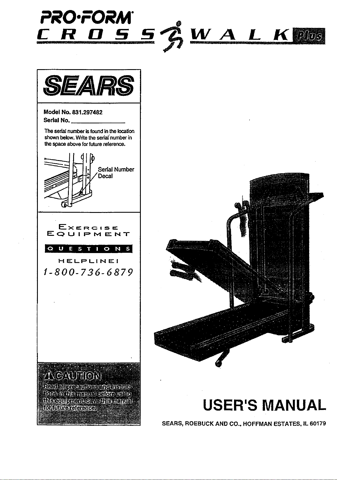
Model No. 831.297482
Serial No.
Theserialnumberisfoundinthelocation
shownbelow.Wdtetheserialnumberin
thespaceaboveforfuturereference.
Sedal Number
/Decal
EQUIPMENT
"onll=n_.l i| II [e] l_il:
HELPLINE!
1-800-73d-6879
USER'S MANUAL
SEARS, ROEBUCK AND CO., HOFFMAN ESTATES, IL 60179

TABLE OF CONTENTS
IMPORTANT PRECAUTIONS .......
BEFORE YOU BEGIN ......... . ...................................................... "...
ASSEMBLY ....................................... _..................................
OPERATION AND ADJUSTMENT ........................................................
HOW TO FOLD AND MOVE THE TREADMILL ..............................................
TROUBLE-SHOOTING .................................................................
CONDITIONING GUIDELINES ...........................................................
ORDERING REPLACEMENT PARTS .................................................. Back Cover
FULL 90 DAY WARRANTY ........ Back Cover
• ,,°,*0* ° = e• °° = ° = o° °° o• °° o_ °° o,* ,el ., o,, = • =°_ • °.t,o
°=*_•°°°°,°°t,°°.=t=°°°,°.•°°•°°°°°°°o°G°°•°°°,°°,°°_*•°°2
_°°°°4
°o°°_5
.... 11
.... 12
.... 14
Note: A HARDWARE IDENTIFICATION CHART, an EXPLODED DRAWING, and a PART LIST are attached to
the center of this manual. Please save them for future reference.
IMPORTANT PRECAUTIONS
.2
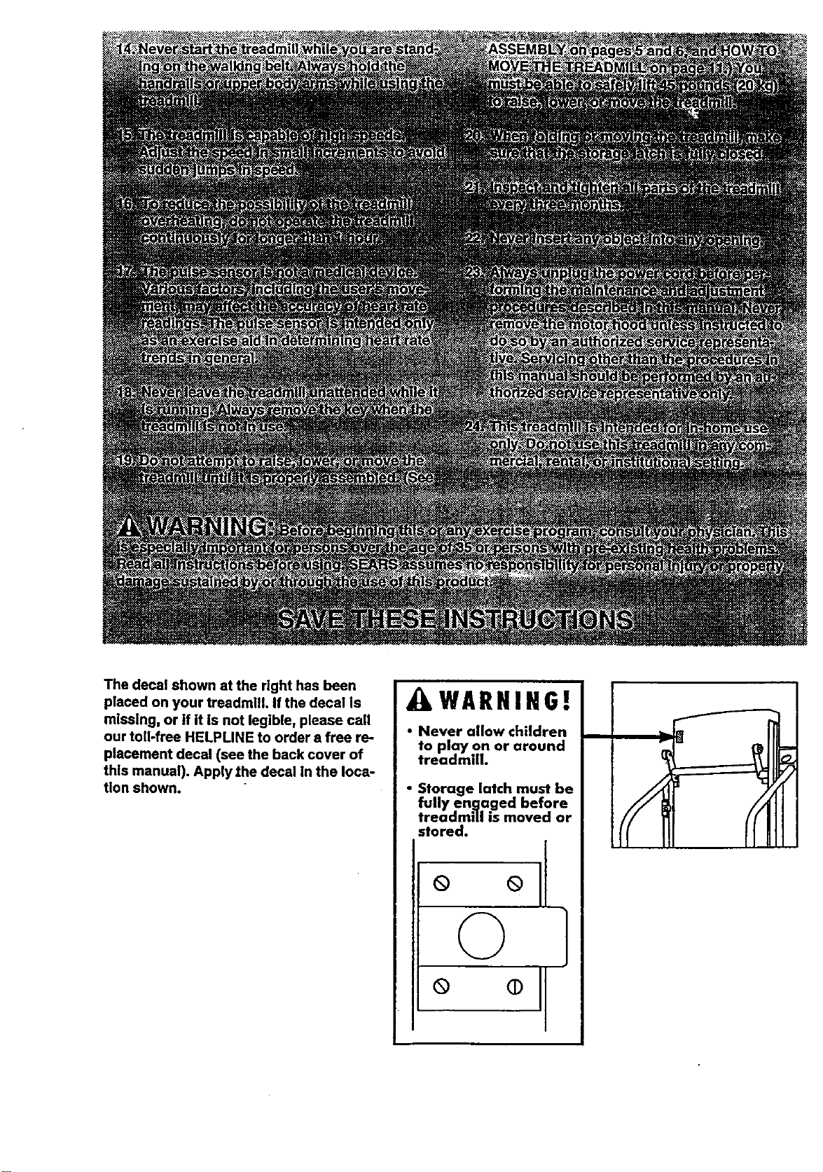
The decal shown at the right has been
placed on your treadmill. If the decal is
missing, or if it is not legible, please call
our toll-free HELPLINE to order a free re-
placement decal (see the back cover of
this manual). Apply the decal In the Ioca-
tion shown.
AWARNIHG!
• Never allow children
to play on or around
treadmdh
• Storage latch must be
fully en.qa.ged before
treadmill is moved or
stored.
ool
© ]
o o]
/F
BEFORE YOU BEGIN
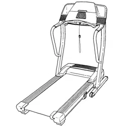
Thank you for sele_ng the PROFORM* CROSSWALK
PLUS treadmill, The CROSSWALK PLUS treadmill
blends advanced lechnology with Innovat_vedesign to
letyou enjoy an excellent form of cardiovascular exer-
cise in the convenience and privacy of your home.
For your benefit, read this manual carefully before
using the treadmill. If you have additional questions,
please call our toll-free HELPLINE at 1-800-736-6879,
Monday through Saturday, 7 a.m, until 7 p.m. Central
Time (excluding holidays). To help us assist you,
please note the product model number and serial num-
ber before calling. The model number of the treadmill
is 8,31.2.97482.The sedal number can be found on a
decal attached to the treadm_ (see the frontcover of
this manual for the locatiOn).
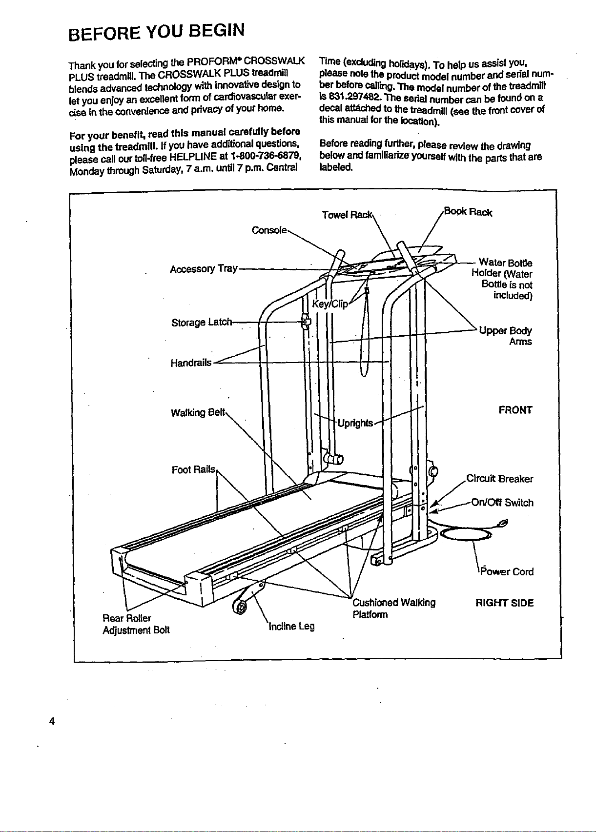
Before reading further, please review the drawing
below and familiarize yourself Withthe parts that are
labeled.
AccessoryTray
Storage
Handrails
Walking Belt_X
Foot Rails
r Bottle
Holder (Water
Bottle is not
included)
Upper Body
Arms
FRONT
Cord
Rear Roller
Adjustment Bolt
WatkJng RIGHT SiDE
Platform
4

ASSEMBLY
CAUTION: Read and follow step I below before removing the restraining tie (see drawing 1). If the restrain-
Ing tie is removed prematurely, sedous bodily injury m=iy result. Assembly requires two people. Set the tread-
millin a cleared area and remove the packing matedals except for the restraining tie. Do not dispose ofthe
packing matedals until assembly is completed. Use the HARDWARE IDENT[RCATION CHART in the center ofthis
manual to identify the parts used in assembly. Assembly requires the Included allen wrench L==_, a phillips
screwdriver _z_), and two adjustable wrenches _.
1. Slide the Left Updght (1) onto the left side of the Base
(59). It may be necessary to firmly push down on the
Left Upright until It Is fully seated on the Base.
Remove the restraining tie from the Base.
Attach the lefthandrail to the Base (59) with a Handrail "
Bolt(93), 3/8" Washer (67), and Handrail Nut (4). Do not
tighten the Handrail Bolt yet. Usingthe ellen wrench,
tighten two Upright Screws (63) intothe LeftUpright (1)
and the Base.
2. Slide the Right Upright (44) ontothe dght side of the
Base (59). It may be necessary to firmly push down
on the Right Upright until it Is fully seated on the
Base, Be careful not to pinch the Wire Harness (25)
between the Right Upright and the Base.
Attach the right handrail to the Base (59) with a Handrail
Bolt(93), 3/8" Washer (67), and Handrail Nut (4). Do not
tighten the Handrail Bolt yeL Using the allen wrench,
tighten two Upright Screws (63) into the Right Updght
(44) and the Base.
Hand tighten the Handrail Nuts (4) used in steps I and 2.
Using a wrench, tighten the Handrail Bolts (93) used in
steps I and 2. Remove the wire ties (not shown) attach-
ingthe Console Base (9) to the Right Upright (44).
59
Restraining
3. Set the Console Base (9) on the Left and Right Uprights
(1, 44). Attach the Console Base with four Screws (75).
While one person carefully feeds any slack Wire Harness
(25) down intothe Right Updght (44), a second person
should carefully pull the slack Wire Harness from the
lower end ofthe Right Updght.
Align the holes in the Book Rack (62) with those in the
Console Base (9). Attach the Book Rack to the Console
Base with four Screws (75) as shown.
6
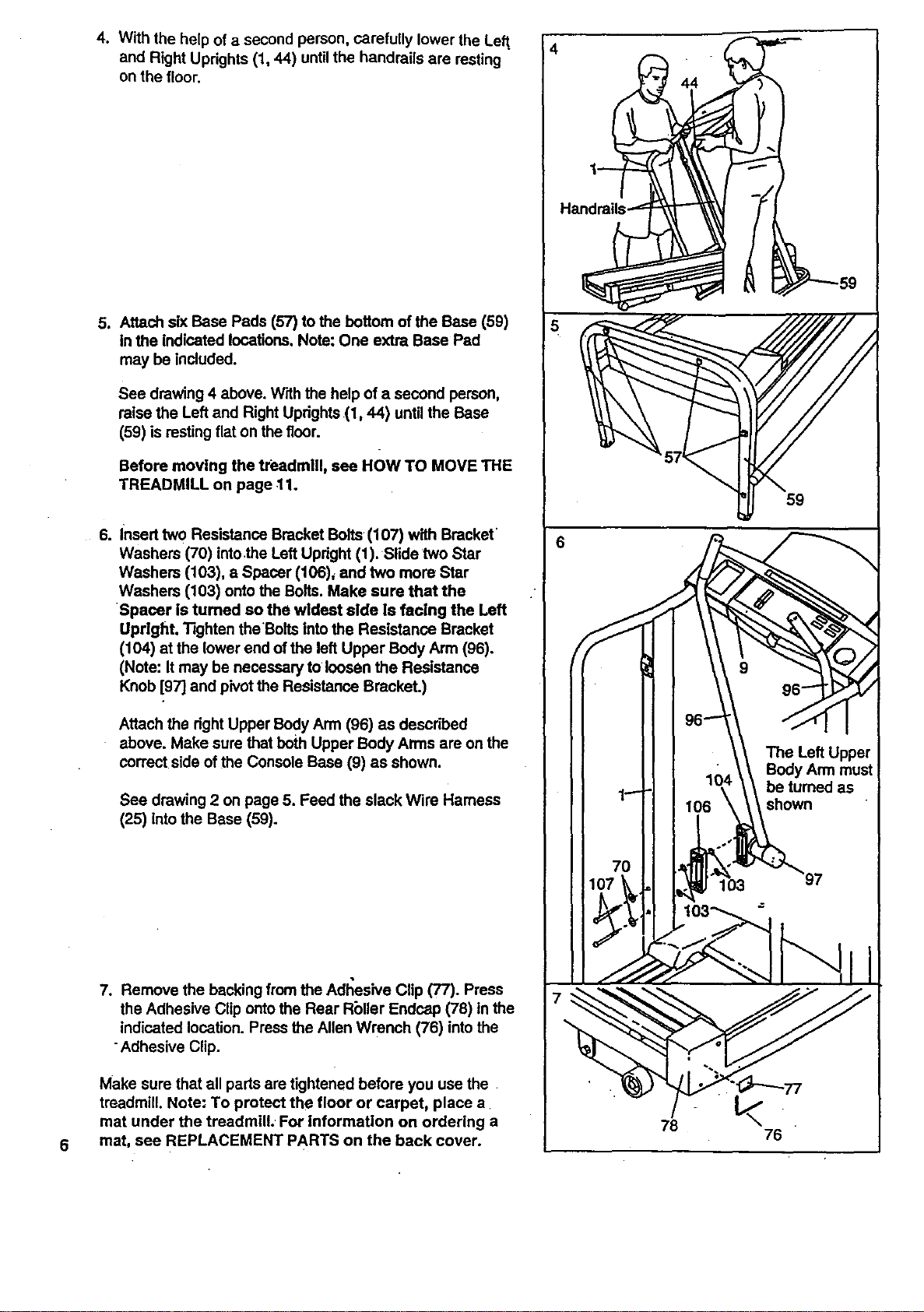
4. With the help of a second person, carefully lower the Left,
and Right Updghts (1, 44) until the handrails are resting
on the floor.
J Attach siXBase Pads (57) to the bottom of the Base (59)
in the indicated locations. Note: One extra Base Pad
may be included.
See drawing 4 above. With the help of a second person,
raise the Left and Right Uprights (1,44) until the Base
(59) is resting flat on the floor.
Before moving the treadmill, see HOW TO MOVE THE
TREADMILL on page 11.
6. Insert two Resistance Bracket Bolts (107) with Bracket
Washers (70) intothe Left Updght (1). Slide two Star
Washers (103), a Spacer (106)_ and two more Star
Washers (103) onto the Bolts. Make sure that the
Spacer is turned so the wideet aide is facing the Left
Upright. Tighten theBolts into the Resistance Bracket
(104) at the lower end of the left Upper Body Arm (96).
(Note: It may be necessary to loosen the Resistance
Knob [97] and pivot the Resistance Bracket.)
Attach the dght Upper BodyArm (96) as descdbed
above. Make sure that both Upper Body Arms are on the
correct side ofthe Console Base (9) as shown.
See drawing 2 on page 5. Feed the slack Wire Harness
(25) intothe Base (59).
7. Remove the backing from the Adl';esive Clip (77). Press
the Adhesive Clip onto the Rear Rbller Endcap (78) in the
indicated location. Press the Allen Wrench (76) into the
Adhesive Clip.
Make sure that all pads are tightened before you use the
treadmill. Note: To protect the floor or carpet, place a
mat under the treadmill. For information on ordering a
mat, see REPLACEMENT PARTS on the back cover.
78
59
76
OPERATION AND ADJUSTMENT
THE PERFORMANT LUBETM WALKING BELT
Your treadmill features a walking belt coated with
PERFORMANT LUBETM, a high-performance lubricanL
IMPORTANT: Never apply silicone spray or other
substances to the walking belt or the walking plat-
form. They will detedorate the walldng belt and
cause excessive wear.
HOW TO PLUG IN THE POWER CORD
electric shock. This product Is equipped with a cord
having an equipment-grounding conductor and a
grounding plug. Plug the power cord Into a surge
protector, and plug the surge protector Into an ap-
propriate outlet that Is properly Installed end
grounded In accordance with all local codes and
ordinances.
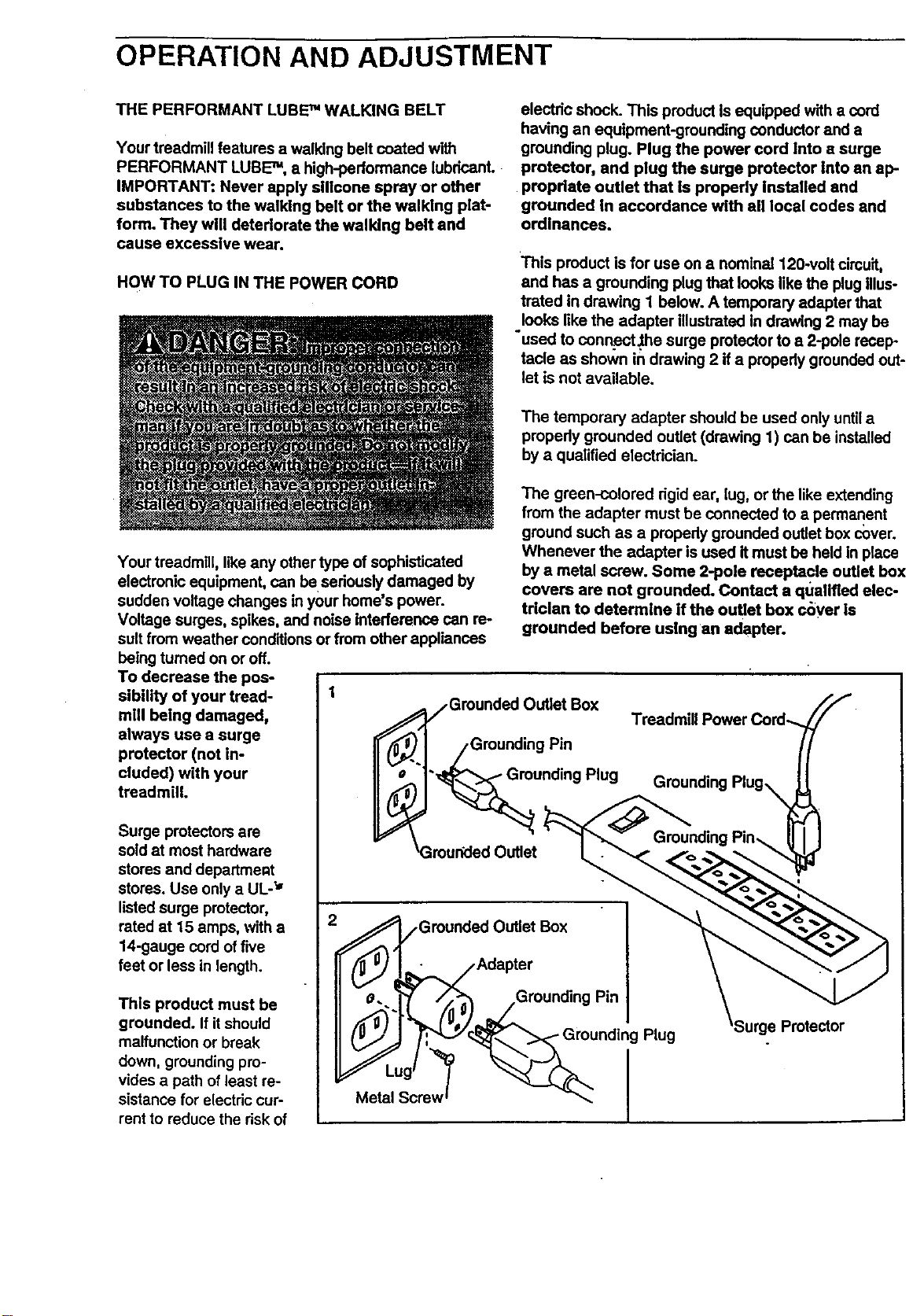
This product is for use on a nominal 120-volt circuit,
and has a grounding plug that looks like the plug Illus-
treted in drawing 1 below. A temporary adapter that
looks like the adapter illustrated In drawing 2 may be
"used to connect _e surge protector to a 2-pole recep-
tacle as shown in drawing 2 if a propedy grounded out-
let is not available.
The temporary adapter should be used only untila
propedy grounded outlet (drawing 1) can be installed
by a qualified electrician.
Your treadmill, like any other type of sophisticated
electronic equipment, can be seriously damaged by
sudden voltage changes in your home's power.
Voltage surges, spikes, and noise interference can re-
suit from weather conditions or from other appliances
being turned on or off.
To decrease the pos-
sibility of your tread- 1
mill being damaged,
always use a surge
protector (not in-
cluded) with your
treadmill.
Surge protectors are
sold at most hardware
stores and department
stores. Use only a UL-_'
listed surge protector,
rated at 15 amps, with a
14-gauge cord of five
feet or less in length.
This product must be
grounded. If itshould
malfunction or break
down, grounding pro-
vides a path of least re-
sistance for electric cur-
rent to reduce the risk of
The green-colored dgid ear, lug, or the like extending
from the adapter must be connected to a permanent
ground such as a propedy grounded outlet box cover.
Whenever the adapter is used it must be held In place
by a metal screw. Some 2-pole receptacle outlet box
covers are not grounded. Contact a qualified elec-
trician to determine if the outlet box c_ver Is
grounded before using an adapter.
jGrounded Outlet Box
• jGrounding Pin
rounding Plug
_Groueded Outlet
Treadmill Power Cord-.
Grounding Piug_
Plug
.=Protector
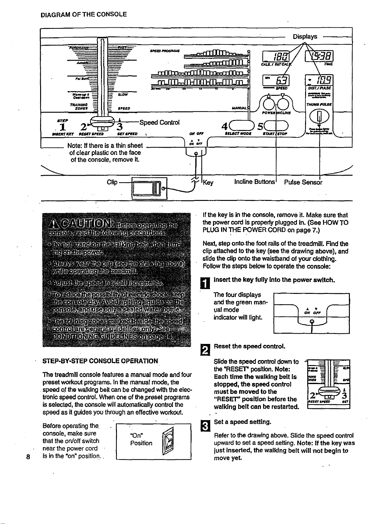
DIAGRAM OF THE CONSOLE
Speed Control 4 5
*_.,,rrx_r _=;=r=-mEo r._r=,a= . o_o, ==_r_,,x rr,.,rr_,.._..___...j.....
Note: If there isa thinsheet / '_' _"
of clear plasticon the face __n.. J
of the console, remove it.
i
Clip
.____e _ Key
J
Incline ButtonsI Pulse Sensor
Ifthe key is in the console, remove it. Make sure that
the power oord is properly plugged in. (See HOWTO
PLUG IN THE pOWER CORD on page 7.)
Next, step onto.the foot railsof the treadmill. Find the
clip attached to the key (see the drawing above), and
slide the clip onto the waistband of your clothing.
Followthe steps below to operate the console:
11
Insert the key fully Into the power switch.
The four displays
and the green man-
ual mode
indicator will light.
ON OFF
8
STEP-BY-STEP CONSOLE OPERATION
The treadmill console features a manual mode and four
preset workout programs. In the manual mode, the
speed of the walldng belt can be changed with the elec-
tronic speed control. When one of the.preset programs
is selected, the console willautomatically control the
speed as itguides you through an effective workout.
e'ore°'nO"I
console, make sure =On"
that the on!off switch Position
near the power cord
is in the "on"position. :
B
[]
Reset the speed control.
Slide the speed control down to
the "RESET" position. Note:
Each time the walking belt is
stopped, the speed control
must be moved to the
"RESET" position before the
walking belt can be restarted.
= _
:WE'll "_ ..
rrT in
Set a speed setting.
Refer to the drawing above. Slide the speed control
upward to set a speed setting. Note: If the key was
iust inserted, the walking belt will 'not begin to
move yet.
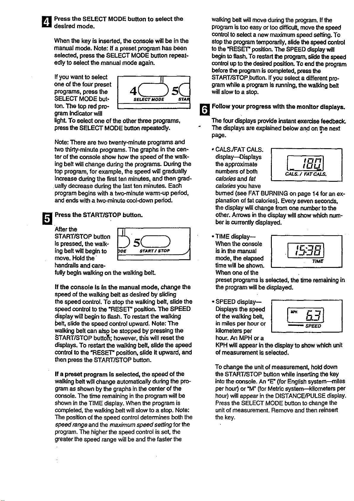
B PresstheSELECTMODEbuttonto selectthe
desiredmode.
When the key is inserted, the console will be in the
manual mode. Note: If a preset program has been
selected, press the SELECT MODE button repeat-
edly to select the manual mode again.
Ifyou want to select
one of the four preset
programs, press the
SELECT MODE but-
ton. The top red pro-
gram Indicator will
lighLTo select one of the otherthree programs,
press the SELECT MODE buttonrepeatedly.
Note: There are two twenty-minute programs and
two thirty-minute programs. The graphs in the cen-
ter of the console show how the speed of the walk-
ing belt will change dudng the programs. During the
top program, for example, the speed will gradually
increase dudng the first ten minutes, and then grad-
ually decrease dudng the last ten minutes. Each
program begins with a two-minute warm-up period,
and ends with a two-minute cool-down pedod.
I_ Press the START/STOP button.
After the
START/STOP button _
ispressed, the walk- 5(_
ing belt will begin to sr,_Rr/STOP
move. Hold the
handrails and care-
fullybegin walking on the walking beit.
If the console is in the manual mode, change the
speed ofthe walking belt as desired by sliding
the speed control To stop the walking belt, slide the
speed control to the =RESET" position. The SPEED
display will begin to flash. To restart the walking
belt, slide the speed control upward. Note: The
walking belt can also be stopped by pressing the
_TART/STOP button; however, this will reset the
displays. To restart the walking belt, slide the speed
controlto the "RESE'C' position, slide it upward, and
then press the START/STOP button.
If a preset program Is selected, the speed of the
walking belt willchange automatically during the pro-
gram as shown by the graphs in the canter of the
console.The time remaining inthe program willbe
shown in the TiME display. When the program is
completed, the walking belt willslow to a stop. Note:
The position of the speed controldetermines both the
speed range and the maximum speed settingfor the
program. The higher the speed control is set, the
greater the speed range willbe and the faster the
walking belt willmove duringthe program. If the
programis too easy or too difficult,move the speed
control to select a new maximum speed setting.To
stopthe programtamporadly, slide the speed control
to the=RESET" position.The SPEED display will
beginto flash. To restart the program, slidethespeed
controlup to thedesired position.To end the program
before the program iscompleted, press the
START/STOPbutton. If you select a different pro-
gram while a program Is running, the walking belt
willslow to a stop.
r,_ Follow your progress with the monitor displays.
The four displays provide instant exercise feedback.
The displays are explained below anclon _e next
page.
CALS ATCALSI I
display_Displays I Cl F'/I
the approximate I LJLJ I
numbers of both CA--LS./ FATC_.S.
calories and fat
calories you have
bumed (see FAT BURNING on page 14 for an ex-
planation of fat calories). Every seven seconds,
the display will change from one number to the
other. Arrows in the display will show which num-
ber is currently displayed.
TMEdsaYI' I
When the conso{e I C -_ Ci
isin the manual • I-.P-J/.J
mode, the elapsed WME
time will be shown.
When one of the
preset programs is selected, the time remaining in
the program willbe displayed.
SPEEOsPaYII I
Displays the speed
ofthe walking belt,
in miles per hour or _ SPEED
kilometers per
hour. An MPH or a
KPH will appear in the display to show which unit
of measurement isselected.
To change the unitof measurement, hold down
the START/STOP button while inserting the key
intothe console. An "E"(for English system--miles
per hour) or "M_(for Metric system-kilometers per
hour) willappear in the DISTANCE/PULSE display.
Pressthe SELECT MODE button to change the
unitof measurement. Remove and then reinsert
the key.
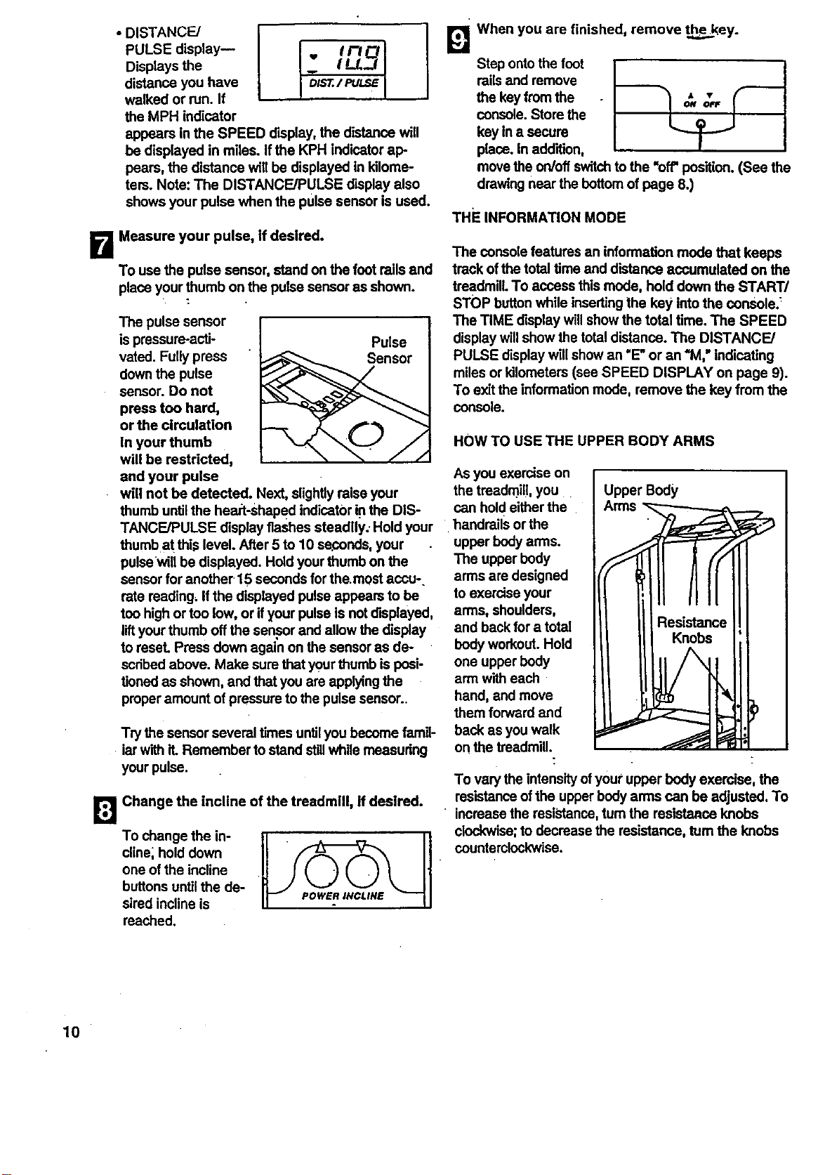
DISTANCE/
I
I - I LL.J
PULSE display-- • I/-/
Displays the
distance you have I DISt./PULSE
walked or run. If
the MPH indicator
appears in the SPEED display, the distance will
be displayed in miles. Ifthe KPH indicator ap-
pears, the distance will be displayed in kilome-
ters. Note: The DISTANCE/PULSE display also
shows your pulse when the pulse sensor is used.
B Measure your pulse, If desired.
To use the pulse sensor, stand on the foot rails and
place your thumb on the pulse sensor as shown.
The pulse sensor
is pressure-acti- Pulse
vated. Fully press _ Sensor
downthe pulse
sensor. Do not
press too hard,
or the circulation
will be restricted,
and your pulse
will not be detected. Next, slightlyraise your
thumb untilthe heart-shaped indicator iFthe DIS-
TANCE/PULSE display flashes steadily: Hold your
thumb at this level. After 5 to 10 seconds, your
pulsewill be displayed. Hold yourthumb on the
sensor for another.15 seconds forthe.most accu-.
rate reading, Ifthe displayed pulse appears to be
too high or too low, or ifyour pulse is not displayed,
liftyourthumb offthe sensor and allow the display
to reset. Press down again on the sensor as de-
scribed above. Make sure that yourthumb is posi-
tioned as shown, and that you are applying the
proper amount of pressure tothe pulsesensor..
Try the sensorseveral timesuntilyou become famil-
iar with it. Remember to stand stillwhile measudng
your pulse.
[]
Change the incline of the treadmlU, if desired.
To change the in-
cline; hold down
one of the incline
buttons untilthe de-
sired incline is
reached.
When you are finished, remove theekey.
gl
Step onto the foot
railsand remove
the keyfrom the
console. Store the
key in a secure
place. In addition,
movethe on/off switchto the "off' position.(Sea the
drawingnear the bottomof page 8.)
THEINFORMA_ONMODE
The console features an information mode that keeps
track of the total time and distance accumulated on the
treadmill. To access this mode, hold down the START/
STOP buttonwhile insertingthe key intothe console._
The TIME display willshow the total time. The SPEED
display willshow the total distance. The DISTANCE/
PULSE display will show an "E"or an "M," indicating
miles or kilometers (see SPEED DISPLAY on page 9).
To exitthe informationmode, remove the key from the
console.
HOW TO USE THE UPPER BODY ARMS
Asyou exercise on
1
the treadmil!,you . Upper Body I
can holdeither the
handrails or the
upper bodyarms.
The upper body
arms are designed
to exercise your
arms, shoulders,
and backfor a total
body workout. Hold
one upper body
arm with each
hand, and move
them forward and
back as you walk
on the treadmill.
To varythe intensityofyour upper body exercise, the
resistanceof the upper body arms can be adjusted. To
• increase the resistance, turn the resistance knobs
clockwise;to decrease the resistance, turnthe knobs
counterclockwise.
10
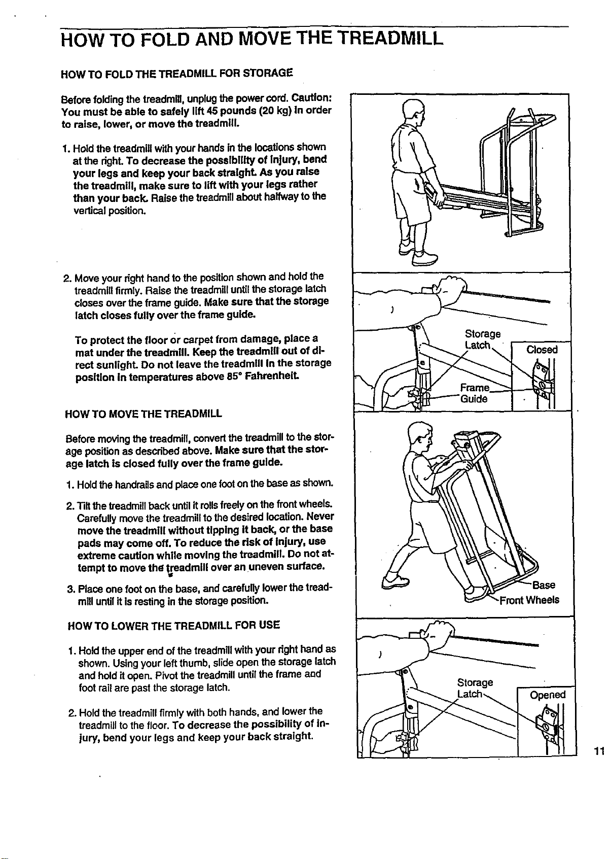
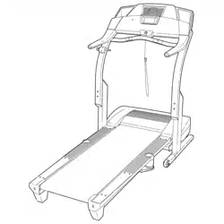
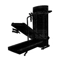
HOW TO FOLD AND MOVE THE TREADMILL
HOW TO FOLD THE TREADMILL FOR STORAGE
Before folding the treadmill, unplug the power cord. Caution:
You must be able to safely llft 45 pounds (20 kg) in order
to raise, lower, or move the treadmill
f. Hold the treadmill with your hands in the locations shown
at the dght. To decrease the possibility of injury, bend
your legs and keep your back straight As you raise
the treadmill, make sure to tiff wlth your legs rather
than your back. Raise the freadmlll about halfway to the
vertical position.
2. Move your right hand to the positionshown and hold the
treadmill firmly. Raise the treadmill until the storage latch
closes over the frame guide. Make sure that the storage
latch closes fully over the frame guide.
To protect the floor or carpet from damage, place a
mat under the treadmill. Keep the treadmill out of di-
rect suntighL Do not leave the treadmill in the storage
position In temperatures above 85° FahrenheiL
HOW TO MOVE THE TREADMILL
Before moving the treadmill, COnvertthe treadmill to the stor-
age positionas descdbed above. Make sure that the stor-
age latch is closed fully over the frame guide.
f. Hold thehandrailsand place one footon thebase as shown.
2. Tiltthe treadmillback until itroilsfreely on the frontwheels.
Carefully move the treadmill to thedesired location. Never
move the treadmill without tipping it back, or the base
pads may come off. To reduce the risk of Injury, use
extreme caution while moving the treadmill. Do not at-
tempt to move the treadmill over an uneven surface.
3. Place one foot on the base, and carefully lower the tread-
mill untJ'Iit is resting in the storage position.
HOWTO LOWER THE TREADMILL FOR USE
1. Hold the upper end of the treadmill with your dght hand as
shown. Using your left thumb, slide open the storage latch
and hold it open. Pivot the treadmill unt_ the frame sod
foot railare past the storage latch.
2. Hold the treadmill firmly with both hands, and lower the
treadmill to the floor. To decrease the possibility of in-
jury, bend your legs and keep your back straight.
11
TROUBLE-SHOOTING
12
Most treadmill problems can be solved by following the slmple steps below. Find the symptom that ap-
plies, and follow the steps listed. If further assistance Is needed, call our toll-free HELPMNE at 1-800-736-
6879, Monday through Saturday, 7 a.m. until 7 p.m. Central Time (excluding holidays).
1. SYMPTOM: THE POWER DOES NOT TURN ON
a. Make sure that the power cord is plugged into a surge protector,and that the surge protector is plugged into
a propedy grounded outlet. (See HOW TO PLUG IN THE POWER CORD on page 7.) Use only a UL-listed
• surge protector, rated at 15 amps, with a 14-gauge cord of fivefeet or less in length.
b. After the power cord has been plugged In, make sure that the key is fully inserted into the console. (See step
1 on page 8.)
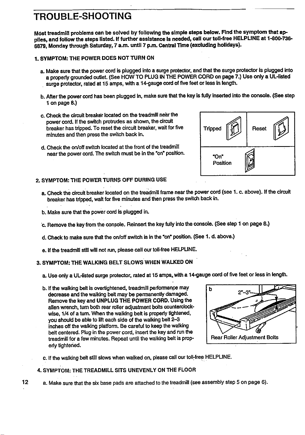
c. Check the circuitbreaker located on the treadmill near the
power cord. Ifthe switch protrudes as shown, the circuit
breaker has tripped. To reset the circuit breaker, wad for five
minutes and then press the switch back in.
d. Check the on/off switch located at the front ofthe treadmill
near the power cord. The switch must be in the "on"position.
Tdpped
Reset
=On"
Position
I
2. SYMPTOM: THE POWER TURNS OFF DURING USE
a. Check the circuit breaker located on the treadmill frame near the power cord (see 1. c. above). Ifthe circuit
breaker has tdpped, wait for five minutes and then press the switch back in.
b. Make sure that the power cord is plugged in.
c, Remove the key from the cor_ole. Reinsed the key fullyintothe console. (See steP 1 on page 8.)
d. Check to make sure that the on/off switch is in the "on"position.(See 1. d. above.)
e. If the treadmill stillwill not run, please call our toll-free HELPMNE.
3. SYMPTOM: THE WALKING BELT SLOWS WHEN WALKED ON
a. Use onlya UL4isted surge protector, rated at 15 amps.with a 14--gaugecord of five feet or less in length.
b. Ifthe walking belt is ovedightened, treadmill performance may
decrease and the walking belt may be permanently damaged.
Remove the key and UNPLUG THE POWER CORD. Using the
allen wrench, turn both rear rolleradjustment bolts counterclock-
wise, 1/4 of a turn. When the walking belt is prepedy tightened,
you should be able to lifteach side of the walking belt 2-3
inches off the walking platform. Be careful to keep the walking
belt centered. Plug in the power cord, insert the key and run the
treadmill for a few minutes. Repeat until the walking belt is prop-
edy tightened.
Rear Roller Adjustment Bolts
c. If the walkingbe t stiI slows when walked on, please call ourtoll-free HELPLINE.
4. SYMPTOM: THE TREADMILL SITS UNEVENLY ON THE FLOOR
a. Make sure that the six base pads are attached to the treadmill (see assembly step 5 on page 6).
5. SYMPTOM: THE WALKING BELT IS OFF-CENTER WHEN WALKED ON
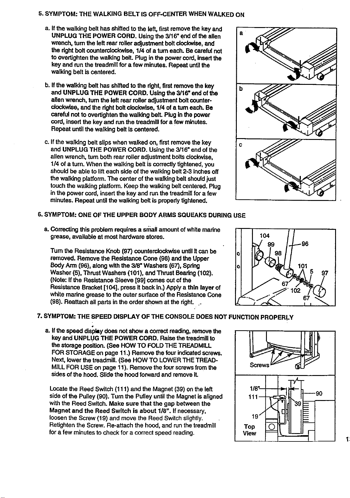
a. Ifthe walking belt has shifted to the left, first remove the key and
UNPLUG THE POWER CORD. Using the 3/16" end of the allen
wrench, tum the left rear roller adjustment boltclockwise, and
the dght bolt counterclockwise, 1/4 of a turn each. Be careful not
to overtighten the walking belt. Plug in the power cord, insed the
key and run the treadmill for a few minutes. Repeat untilthe
walking belt is centered.
b. If the walking belt has shifted to the dght, first remove the key
and UNPLUG THE POWER CORD. Using the 3/16" end of the
allen wrench, tum the left rear roller adjustment boltcounter-
clockwise, and the dght bolt clockwise, 1/4 of a turn each. Be
careful not to ovedighten the walking bell. Plug in the power
cord, insed the key and runthe treadmill for a few minutes.
Repeat until the walking belt is centered.
c. If the walking belt slips when walked on, first remove the key
and UNPLUG THE POWER CORD. Using the 3/16" end of the
allen wrench, turn both rear roller adjustment boltsclockwise,
1/4 of a turn. When the walking belt is correctly tightened, you
should be able to lifteach side of the walking belt 2-3 inches off
the walking platform. The center of the walking belt shouldjust
touch the walking platform. Keep the walking belt centered. Plug
in the power cord, insed the key and run the treadmill for a few
minutes. Repeat until the walking belt is prepedy tightened.
a
6. SYMPTOM: ONE OF THE UPPER BODY ARMS SQUEAKS DURING USE
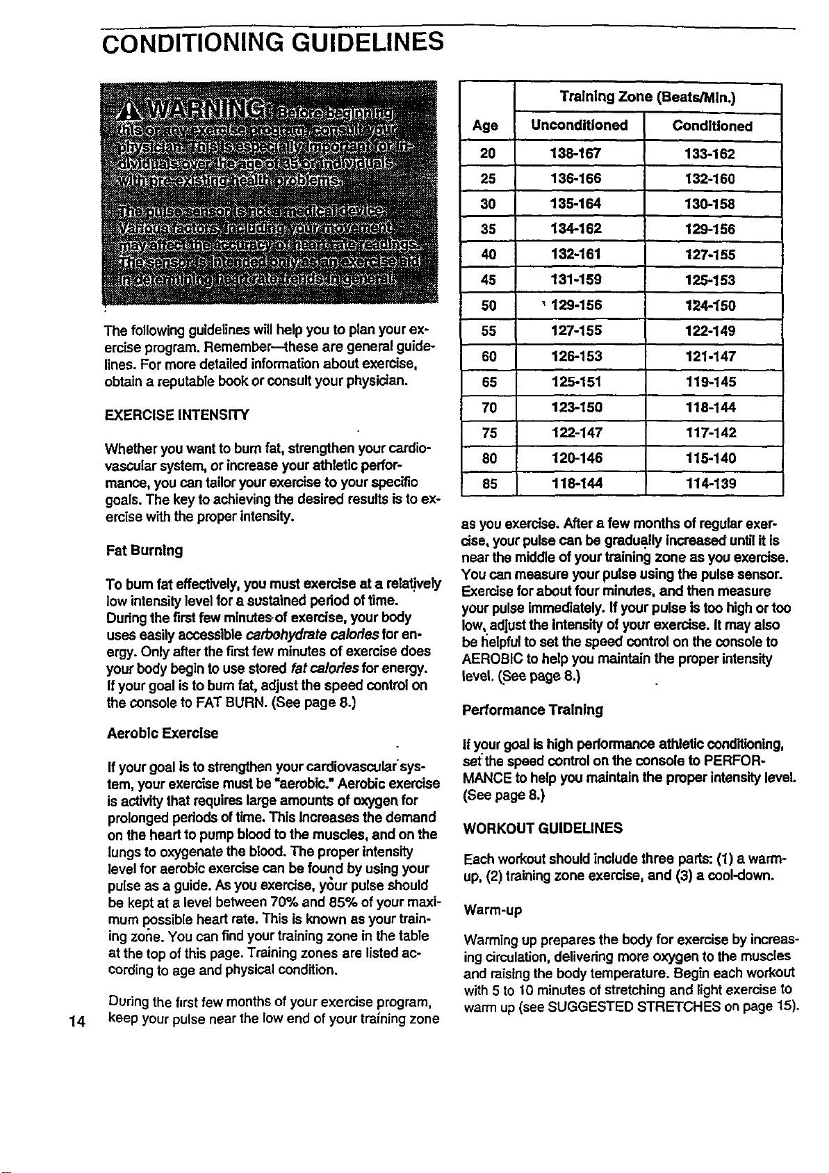
a. Correcting this problem requires a srnail amount ofwhite madne
grease, available at most hardware stores.
Tum the Resistance Knob (97) counterclockwise until it can be
removed. Remove the Resistance Cone (98) and the Upper
Body Arm (96), along wllh the 3/8" Washers (67), Spdng
Washer (5), Thrust Washers (101), and Thrust Beadng (102).
(Note: Ifthe Resistance Sleeve [99] comes out of the
Resistance Bracket [104], press it back in.) Apply a thin layer of
white marine grease to the outer surface of the Resistance Cone
(98). Reattach all parts in the order shown at the dght...
104
99
101
7. SYMPTOM: THE SPEED DISPLAY OF THE CONSOLE DOES NOT FUNCTION PROPERL.Y
a. Ifthe speed display does not show a correct reading, remove the
key and UNPLUG THE POWER CORD. Raise the treadmill to
the storage position. (See HOW TO FOLD THE TREADMILL
FOR STORAGE on page 11.) Remove the four indicatedscrews.
Next, lower the treadmill. (See HOW TO LOWER THE TREAD-
MiLL FOR USE on page 11). Remove the four screws from the
sides of the hoed. Slide the hood forward and remove it.
Locate the Reed Switch (111) and the Magnet (39) on the left
side of the Pulley (90). Tum the Pulley until the Magnet is aligned
with the Reed Switch. Make sure that the gap between the
Magnet and the Reed Switch is about 1/8". If necessary,
loosen the Screw (19) and move the Reed Switch slightly.
Retighten the Screw. Re-attach the hood, and run the treadmill
for a few minutes to check for a correct speed reading.
--/-_
111-- 90
Top
View
CONDITIONING GUIDELINES
14
The following guidelines will help you to plan your ex-
ercise program. Remember--these are general guide-
lines. For more detailed information about exercise,
obtain a reputable book or consult your physician.
EXERCISE INTENSITY
Whether you want to bum fat, strengthen your cardio-
vascular system, or increase your athletic perfor-
mance, you can tailor your exercise to your specific
goals. The key to achieving the desired results isto ex-
emise with the proper intensity.
Fat Burning
To bum fat effectively, you must exercise at a relaUvety
low intensity level for a sustained period oftime.
During the first few mlnutesof exercise, your body
uses easily accessible carbohydrate calories for en-
ergy. Only after the first few minutes of exercise does
your body begin to use stored fat calories for energy.
Ifyour goal is to bum fat, adjust the speed control on
the console to FAT BURN. (See page 8.)
Aerobic Exercise
If your goal is to strengthen your cardiovascularsys-
tem, your exercise must be "aerobic." Aerobic exercise
is activitythat requires large amounts of oxygen for
prolonged periods oftime. This Increases the demand
on the head to pump bloodto the muscles, and on the
lungs to oxygenate the blood. The proper intensity
level for aerobic exercise can be found by using your
pulse as a guide. As you exercise, your pulse should
be kept at a level between 70% and 85% of your maxi-
mum .possibleheart rate. This is known as your train-
ing zone. You can find your training zone in the table
at the top ofthis page. Training zones are listed ac-
Cordingto age and physical condition.
During the first few monthsof your exercise program,
keep your pulse near the low end of your training zone
Training Zone (Beats/MIn.)
Age Unconditioned
20 138-167
25 136-166
30 135-164
35 134-162
40 132-161
45 131-159
50 _ 129-156
55 127-155
60 126-153
65 125-151
70 123-150
75 122-147
80 120-146
85 116-144
Conditioned
133-162
132-160
130-158
129-156
127-155
125-153
124-1'50
122-149
121-147
119-145
118-144
117-142
115-140
114-139
as you exercise. After a few months of regular exer-
cise, your pulse can be gradually increased untilit is
near the middle of your training zone as you exercise.
You can measure your pulse using the pulse sensor.
Exercise for about four minutes, and then measure
your pulse immediately. If your pulse is too high or too
Iow,.edjustthe intensity of your exercise. It may also
be helpfulto set the speed control on the console to
AEROBIC tohelp you maintain the proper intensity
level. (.Seepage 8.)
Performance Training
Ifyour goal is high performance athletic conditioning,
set the speed controlon the console to PERFOR-
MANCE to help you maintain the proper intensity level.
(See page 8.)
WORKOUT GUIDELINES
Each workout should include three pads: (1) a warm-
up, (2) training zone exercise, and (3) a cool-down.
Warm-up
Warming up prepares the body for exercise by increas-
ingcirculation,delivering more oxygen to the muscles
and raisingthe body temperature. Begin each workout
with 5 to 10 minutes of stretching and light exercise to
warm up (see SUGGESTED STRETCHES on page 15).
Training Zone Exercise
After warming up, increase the intensity of your exer-
cise until your pulse isin your training zone for 20 to
60 minutes. (During the first few weeks of your exer-
cise program, do not keep your pulse in your training
zone for longer than 20 minutes.) Breathe regularly
and deeply as you exemise--never hold your breath.
Cool-down
Finish each workout with 5 to 10 minutes of stretching
to cool down. This will increase the flexibility of your
muscles and will help to prevent post-exercise problems.
Exercise Frequency
To maintain or improve your condifion, complete three
workouts each week, with at least one day of restbe-
tween workouts. After a few months, you may com-
plete up to five workouts each week if desired.
The key tosuccess is to make exerctse.a regular and
enjoyable part ofyour everyday life.
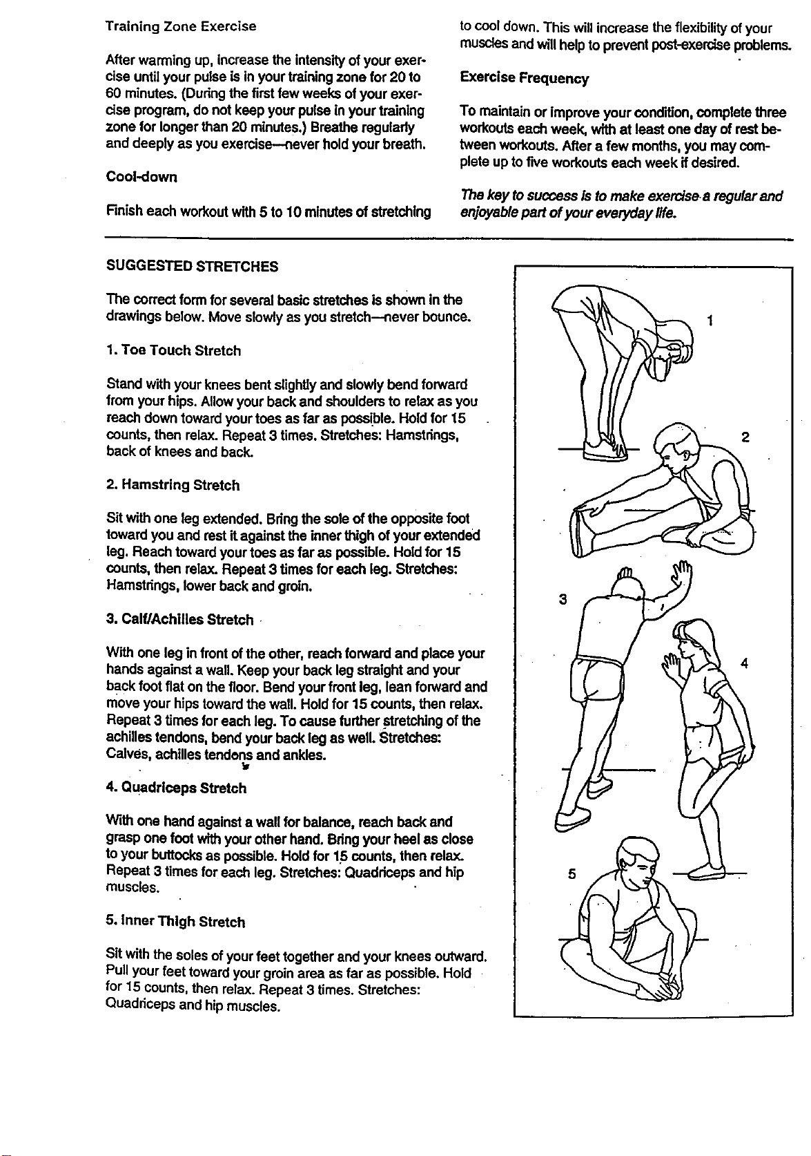
SUGGESTED STRETCHES
The correct form for several basic stretches is shown in the
drawings below. Move slowly as you stretch--never bounce.
1. Toe Touch Stretch
Stand with your knees bent slightlyand slowly bend forward
from your hips. Allow your back and shoulders to relax as you
reach down toward your toes as far as possible. Hold for 15
counts, then relax. Repeat 3 times. Stretches: Hamstrings,
back of knees and back.
2. Hamstring Stretch
Sit with one leg extended. Bringthe sole of the opposite foot
toward you and rest it against the inner thigh of your extended
leg. Reach toward your toes as far as possible. Hold for 15
counts, then relax. Repeat 3 times for each leg. Stretches:
Hamstrings, lower back and groin.
3. Calf/Achitiea Stretch
With one leg in front of the other, reach forward and place your
hands against a wall. Keep your back leg straight and your
back foot fiat on the floor. Bend yourfront leg, lean forward and
move your hipstoward the wall. Hold for 15 counts, then relax.
Repeat 3 times for each leg. To cause further stretching of the
achilles tendons, bend your back leg as well. Stretches:
Calves, achilles tendens and ankles.
4. Quadrloeps Stretch
With one hand against a wall for balance, reach back and
grasp one foot with your other hand. Bdng your heel as close
to your buttocks as possible. Hold for 15 counts, then relax.
Repeat 3 times for each leg. Stretches: Quadriceps and hip
muscles.
5. Inner Thigh Stretch
Sit with the soles of yourfeet together and your knees outward.
Pullyour feet toward your groinarea as far as possible. Hold
for 15 counts, then relax. Repeat 3 times. Stretches:
Quaddceps and hipmuscles.
2
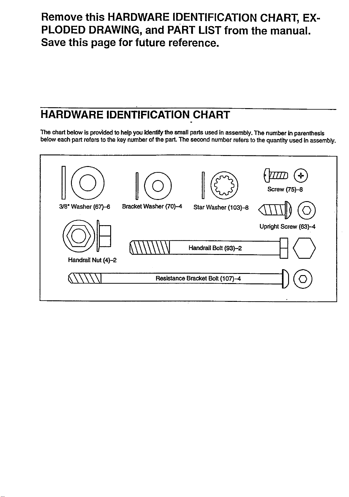
Remove this HARDWARE IDENTIFICATION CHART, EX-
PLODED DRAWING, and PART LIST from the manual.
Save this page for future reference.
HARDWARE IDENTIFICATION CHART
The chart below is provided to helpyou Identifythe small parts used in assembly, The number in parenthesis
below each part refers to the key number of the part. The second number refers to the quantity used in assembly,
l© H©
3/8" Washer (67)-6 Bracket Washer (70)-4 Star Washer (103)-6
Handrail Nut (4)-2
_\\\\\\\_J HandratlSolt(93)-2
Screw (75)-8
Upright Screw (63)-4
_\\\\\1 R_istanemSracketBolt(,O7)--4 D_
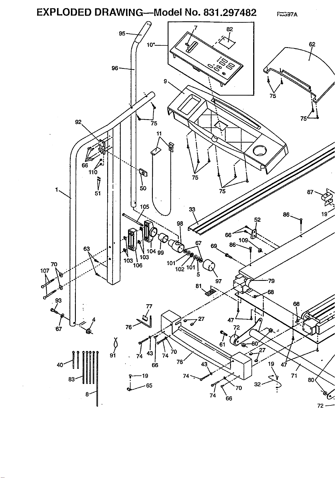
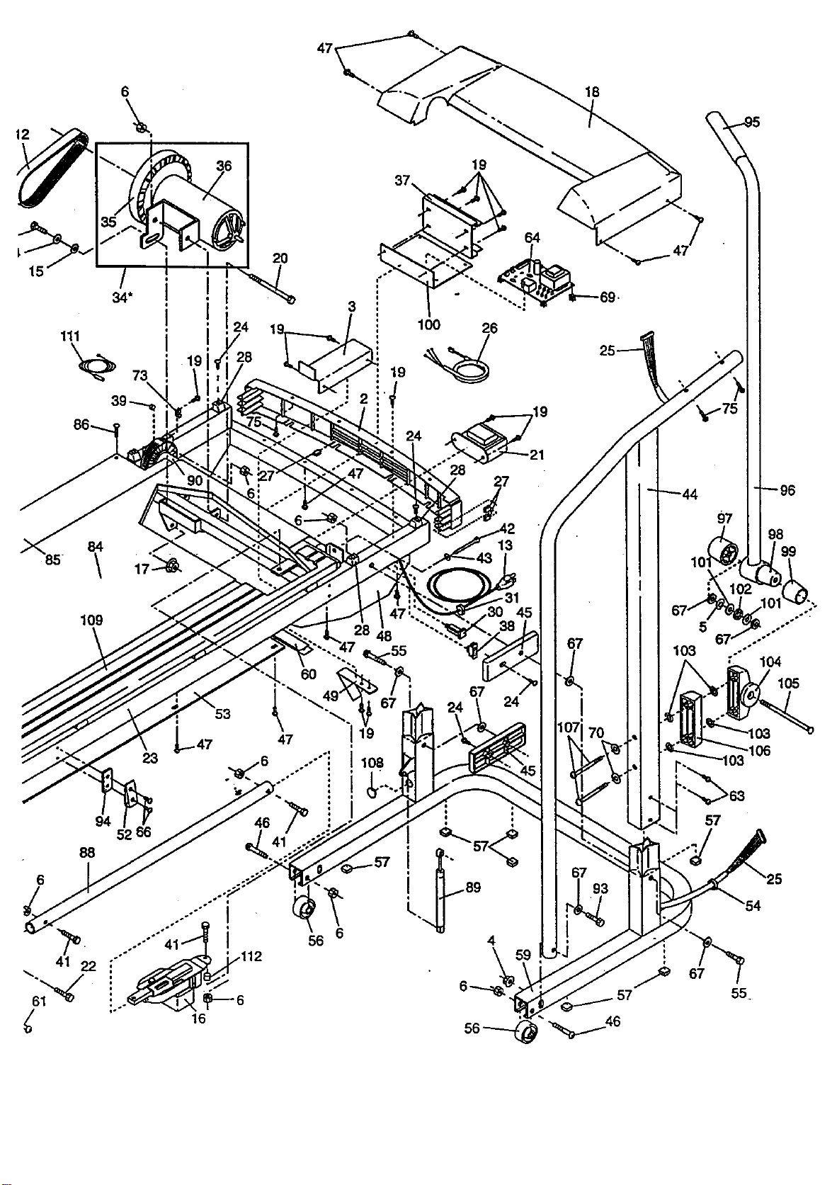
EXPLODED DRAWING--Model No. 831.297482
82
70
107
93
"67
110
51
96--"---
75
11
103
106
77
98
102
75
33
67
5
81
\
75
69
97
47
72
43
74 66
52
27
F_97A
68
62
72 ---'--
i
86_.
19
3
100 26
+
I
27
84
\
109
/°
48
13
94 5"266
88
41 22
16
6
56
67
t 24
I q
4
18
I
67
98
'99
: 104
105
57
i
i
67
55+
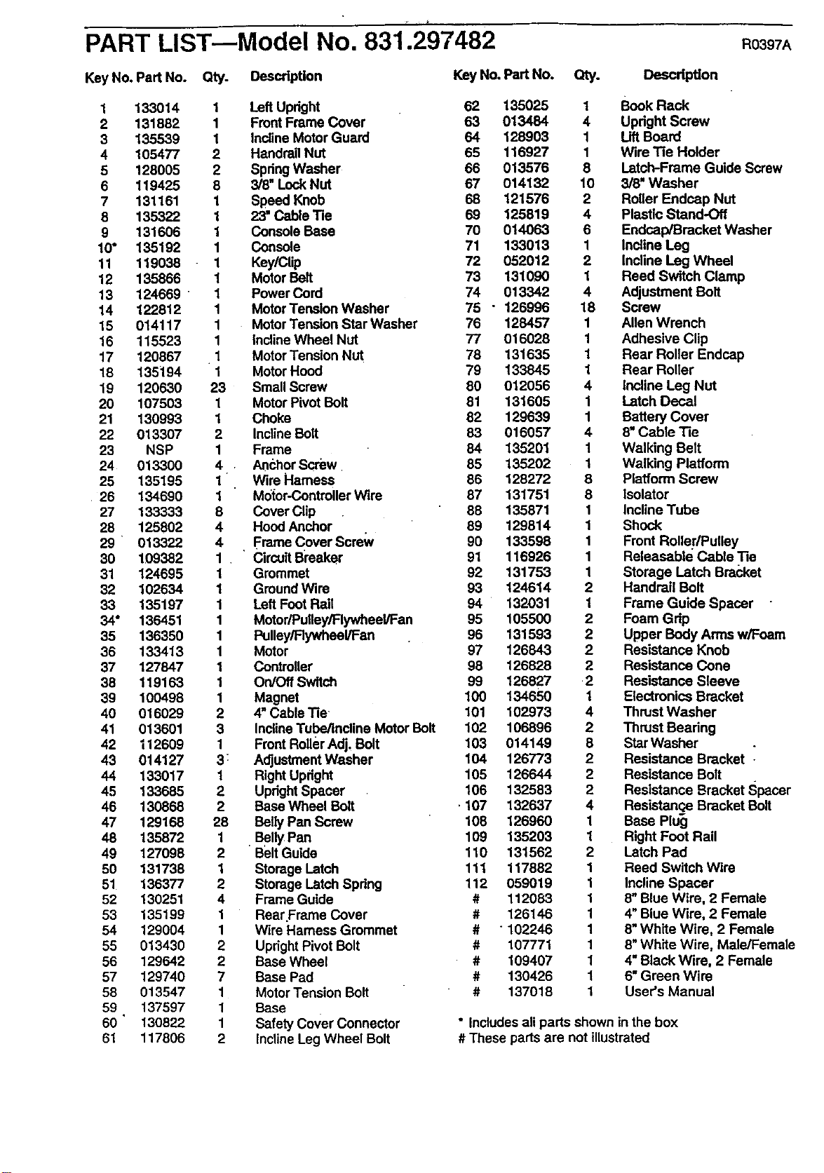
PART LIST--Model No. 831.297482 RO397A
Key No. Part No. Qty. Description
1 133014
2 131882
3 135539
4 105477
5 128005
6 119425
7 131161
8 135322
9 131606
10" 135192
11 119038
12 135866
13 124669
14 122812
15 014117
16 115523
17 120867
18 135194
19 120530
20 107503
21 130993
22 013307
23 NSP
24 013300
25 135195
26 134690
27 133333
28 125802
29 013322
30 109382
31 124695
32 102634
33 135197
34° 136451
35 136350
36 133413
37 127847
38 119163
39 100498
40 016029
41 013601
42 112609
43 014127
44 133017
45 133685
46 130868
47 129168
48 135872
49 127098
50 131738
51 136377
52 130251
53 135199
54 129004
55 013430
56 129642
57 129740
58 013547
59 137597
60 ' 130822
61 117806
1
1
1
2
2
8
1
1
1
1
1
1
1
1
1
1
1
1
23
1
1
2
1
4
1
1
8
4
4
1
1
1
1
1
1
1
1
1
1
2
3
1
3:
1
2
2
28
1
2
1
2
4
1
1
2
2
7
1
1
1
2
Left Updght
Front Frame Cover
Incline Motor Guard
Handrail Nut
SpringWasher
3/8" Lock NUt
Speed Knob
23" Cable Tie
Console Base
console
Key/Clip
Motor Belt
Power Cord
MotorTension Washer
MotorTension Star Washer
InclineWheel Nut
MotorTension Nut
Motor Hood
Small Screw
Motor Pivot Bolt
Choke
InclineBolt
Frame
AnchorScrew
Wire Harness
Motor-ControllerWire
Cover Clip
Hood Anchor
Frame Cover ScreWy
CircuitBreaker
Gmmmet
GroundWire
Left Foot Rail
Motor/Pulley/Flywheel/Fan
Pulley/Flywheel/Fan
Motor
controller
On/Off Switch
Magnet
4"Cable Tie
InclineTube/Incline Motor Bolt
Front RollerAdj, Bolt
AdjustmentWasher
Right Upright
UprightSpacer
Base Wheel Bolt
Belly Pan Screw
Belly Pan
BEltGuide
Storage Latch
Storage Latch Spring
Frame Guide
Rear Frame Cover
Wire Harness Grommet
UprightPivot Bolt
Base Wheel
Base Pad
Motor Tension Bolt
Base
Safety Cover connector
InclineLeg Wheel Bolt
Key No. Part No. Qty.
62 135025
63 013484
64 128903
65 116927
66 013576
67 014132
68 121576
69 125819
70 014063
71 133013
72 052012
73 131090
74 013342
75 " 126996
76 128457
77 016028
78 131635
79 133845
80 012056
81 131605
82 129639
83 016057
84 135201
85 135202
86 128272
87 131751
88 135871
89 129814
90 133598
91 116926
92 131753
93 124614
94 132031
95 105500
96 131593
97 126843
98 126828
99 126827
100 134650
101 102973
102 106896
103 014149
104 126773
105 126644
106 132583
107 132637
108 12696O
109 135203
110 131562
111 117882
112 059019
# 112053
# 126146
# "102246
# 107771
# 109407
# 130426
# 137018
DescripUon
1 Book Rack
4 Upright Screw
1 Lift Board
1 Wire Tie Holder
8 Latch-Frame Guide Screw
10 3/8" Washer
2 Roller Endcap Nut
4 Plastic Stand-Off
6 Endcap/Bracket Washer
1 Incline Leg
2 Incline Leg Wheel
1 Reed Switch Clamp
4 Adjustment Bolt
18 Screw
1 Allen Wrench
1 Adhesive Clip
1 Rear Roller Endcep
1 Rear Roller
4 Incline Leg Nut
1 Latch Decal
1 Battery Cover
4 8"Cable Tie
1 Walking Belt
1 Walking Platform
8 Platform Screw
8 Isolator
1 Incline Tube
1 Shock
1 Front Roller/Pulley
1 Releasable Cable "Re
1 Storage Latch Bracket
2 Handrail Bolt
1 Frame Guide Spacer
2 Foam Gdp
2 Upper Body Arms w/Foam
2 Resistance Knob
2 Resistance cone
2 Resistance Sleeve
1 Electronics Bracket
4 Thrust Washer
2 Thrust Bearing
8 Star Washer
2 Resistance Bracket
2 Resistance Bolt
2 Resistance Bracket Spacer
4 Resistance Bracket Bolt
1 Base Plug
1 Right Foot Rail
2 Latch Pad
1 Reed Switch Wire
1 Incline Spacer
1 8" Blue Wire, 2 Female
1 4" Blue Wire, 2 Female
1 8"White Wire, 2 Female
1 8"White Wire, Male/Female
1 4" Black Wire, 2 Female
1 6" Green Wire
1 User's Manual
• Includes all parts shown in the box
# These parts are not illustrated

SWA/R,.
Model No, 831.297482
QUESTIONS?
If you find that:
• you need help assembling or
operating the PROFORM •
CROSSWALK PLUS treadmill
• a part is missing
• or you need to schedule repair
service
call our toll-free HELPLINE
1-800-736-6879
Monday-Saturday, 7 am-7 pm
Central Time (excluding holidays)
REPLACEMENT
PARTS
If parts become worn andneed
to be replaced, call the following
toll-free number
1-800-FON-PART
(1-800-366-7278)
The model number and sedal number of your PROFORM • CROSS-
WALK PLUS treadmill are listed on a decal attached to the frame.
See the front cover of this manual to find the location of the decal.
All replacament parts are available for immediate purchase or
special order when you visit your nearest SEARS Sewtce Center.
To request service or to order pads by telephone, call the toll-free
numbers listedat the left.
When requesting help or service, or ordedng parts, please be pre-
pared to providethe following information:
• The NAME OF THE PRODUCT (PROFORM • CROSSWALK
PLUS treadmill)
• The MODEL NUMBER OFTHE PRODUCT (831.297482)
• The PART NUMBER OF THE PART (see the EXPLODED
DRAWING and PART LIST included n this manual)
• The DESCRIPTION OF THE PART (see the EXPLODED DRAW-
ING and PART LIST included in this manuan.
FULL 90 DAY WARRANTY
For 90 days from the date of purchase, if failure occursdue todefect in material or workmadship in this
SEARS TREADMILL EXERCISER, contact the nearest SEARS Service Center throughout the United
States and SEARS will repair or replace the TREADMILL EXERCISER, free of charge.
ThiswarrantydoesnotapplywhentheTREADMILLEXERCISERisusedcommemiallyorf9rrentalpur-
poses.
This warranty gives you specific legal dghts, and you may also have other dghts which vary from state
to state.
SEARS, ROEBUCK AND CO., DEPT. 817WA, HOFFMAN ESTATES, IL 60179
Part No. 137018 G00782-C R0397A Printed in USA © 1997 Sears, Roebuck and Co.