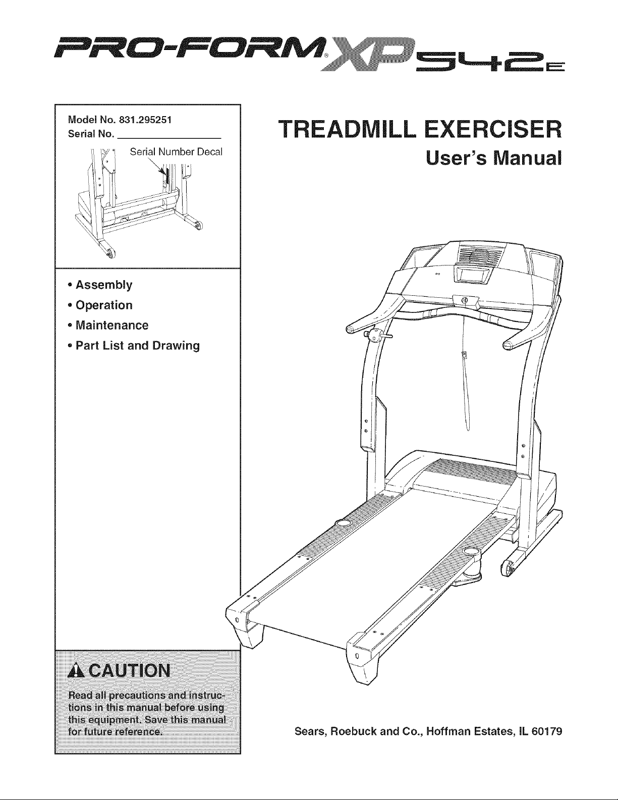
Model No. 831.295251
Serial No.
Serial Number Decal
oAssembly
Operation
•Maintenance
= Part List and Drawing
TR LL EXERCISE
User's Manual
Sears, Roebuck and Co., Hoffman Estates, IL 60179
TABLE OF CONTENTS
IMPORTANT PRECAUTIONS ................................................................ 2
BEFORE YOU BEGIN ...................................................................... 4
ASSEMBLY ............................................................................... 5
OPERATION AND ADJUSTMENT ............................................................. 8
HOW TO FOLD AND MOVE THE TREADMILL .................................................. 21
TROUBLESHOOTING ..................................................................... 22
CONDiTiONiNG GUiDELiNES ............................................................... 24
PART LiST .............................................................................. 26
PART iDENTiFiCATION CHART ............................................................. 27
ORDERING REPLACEMENT PARTS .................................................. Back Cover
FULL 90 DAY WARRANTY .......................................................... Back Cover
Note: An EXPLODED DRAWING is attached in the center of this manual.
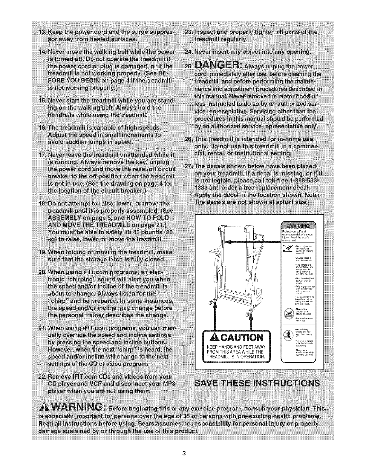
IMPORTANT PRECAUTIONS
BEFORE YOU BEGIN
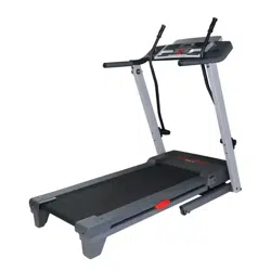
Thank you for selecting the revolutionary PROFORM ®
XP 542e treadmill. The XP 542e treadmill offers an im-
pressive array of features designed to make your
workouts at home more enjoyable and effective. And
when you're not exercising, the unique XP 542e tread-
mill can be folded up, requiring less than half the floor
space of other treadmills.
For your benefit, read this manual carefully before
using the treadmill. If you have questions after read-
ing this manual, call 1-800-4-MY-HOME ®(1-800-469-
4663).To help us assist you, please note the product
model number and serial number before calling. The
model number of the treadmill is 831.295251. The ser-
ial number can be found on a decal attached to the
treadmill (see the front cover of this manual for the lo-
cation).
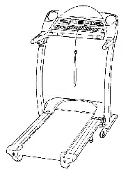
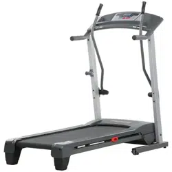
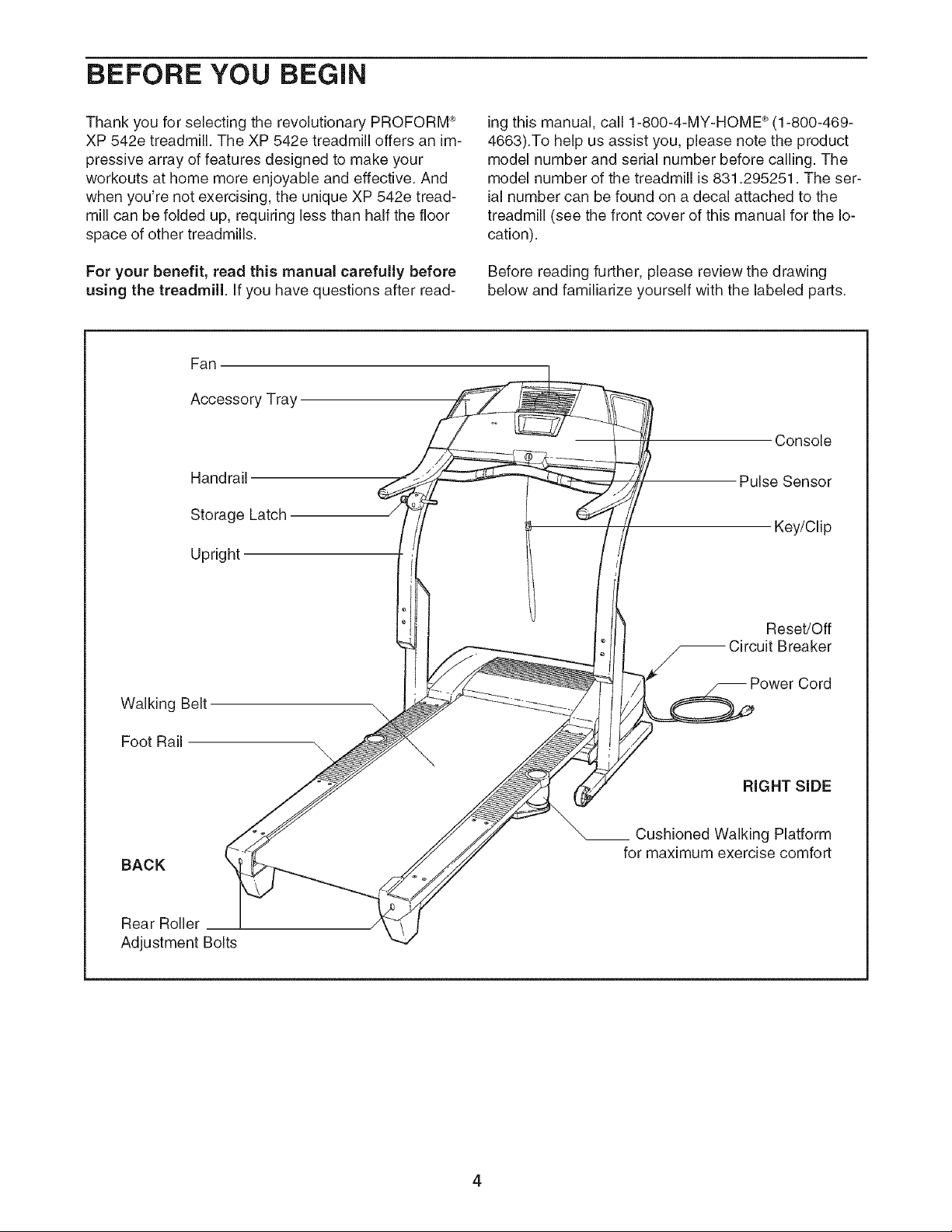
Before reading further, please review the drawing
below and familiarize yourself with the labeled parts.
Fan
Accessory Tray
Handrail
Storage Latch
Upright
Walking Belt
Foot Rail
BACK!
Rear Roller
Adjustment Bolts
Console
Pulse Sensor
Key/Clip
Reset/Off
Breaker
RIGHT SiDE
Cushioned Walking Platform
for maximum exercise comfort
4
ASSEMBLY
Assembly requires two persons. Set the treadmill in a cleared area and remove all packing materials. Do not
dispose of the packing materials until assembly is completed. Note: The underside of the treadmill walking belt is
coated with high-performance lubricant. During shipping, a small amount of lubricant may be transferred to the
top of the walking belt or the shipping carton. This is a normal condition and does not affect treadmill perfor-
mance. If there is lubricant on top of the walking belt, simply wipe off the lubricant with a soft cloth and a mild,
non-abrasive cleaner.
Assembly requires the included allen wrenches ) and your own phillips screwdriver (_======_,
and wire cutters _ _
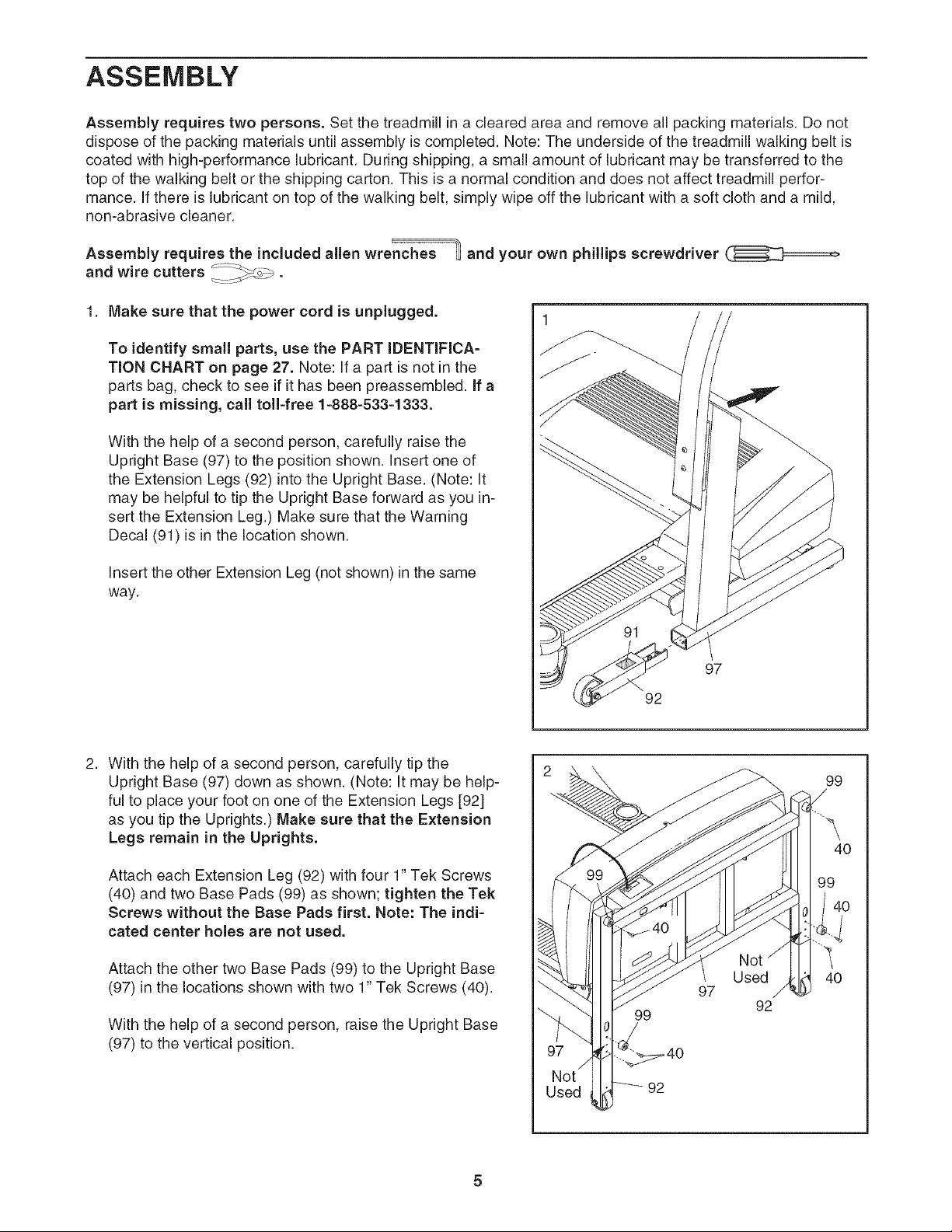
1. Make sure that the power cord is unplugged.
To identify small parts, use the PART IDENTIFICA-
TION CHART on page 27. Note: If a part is not in the
parts bag, check to see if it has been preassembled. If a
part is missing, call toll=free 1 =888=533=1333.
With the help of a second person, carefully raise the
Upright Base (97) to the position shown. Insert one of
the Extension Legs (92) into the Upright Base. (Note: It
may be helpful to tip the Upright Base forward as you in-
sert the Extension Leg.) Make sure that the Warning
Decal (91) is in the location shown.
Insert the other Extension Leg (not shown) in the same
way.
97
92
With the help of a second person, carefully tip the
Upright Base (97) down as shown. (Note: It may be help-
ful to place your foot on one of the Extension Legs [92]
as you tip the Uprights.) Make sure that the Extension
Legs remain in the Uprights.
Attach each Extension Leg (92) with four 1" Tek Screws
(40) and two Base Pads (99) as shown; tighten the Tek
Screws without the Base Pads first. Note: The indi-
cated center holes are not used.
Attach the other two Base Pads (99) to the Upright Base
(97) in the locations shown with two 1" Tek Screws (40).
With the help of a second person, raise the Upright Base
(97) to the vertical position.
99
97
92
99
99
40
40
3. 3
AttachtheLatchAssembly(82)totheLeftUpright(84)
withthetwoLatchScrews(46);start bothLatch
Screwsbeforetighteningeitherof them.Note:The
LatchScrewsmaybepreattachedtotheLeftUpright.
46 82
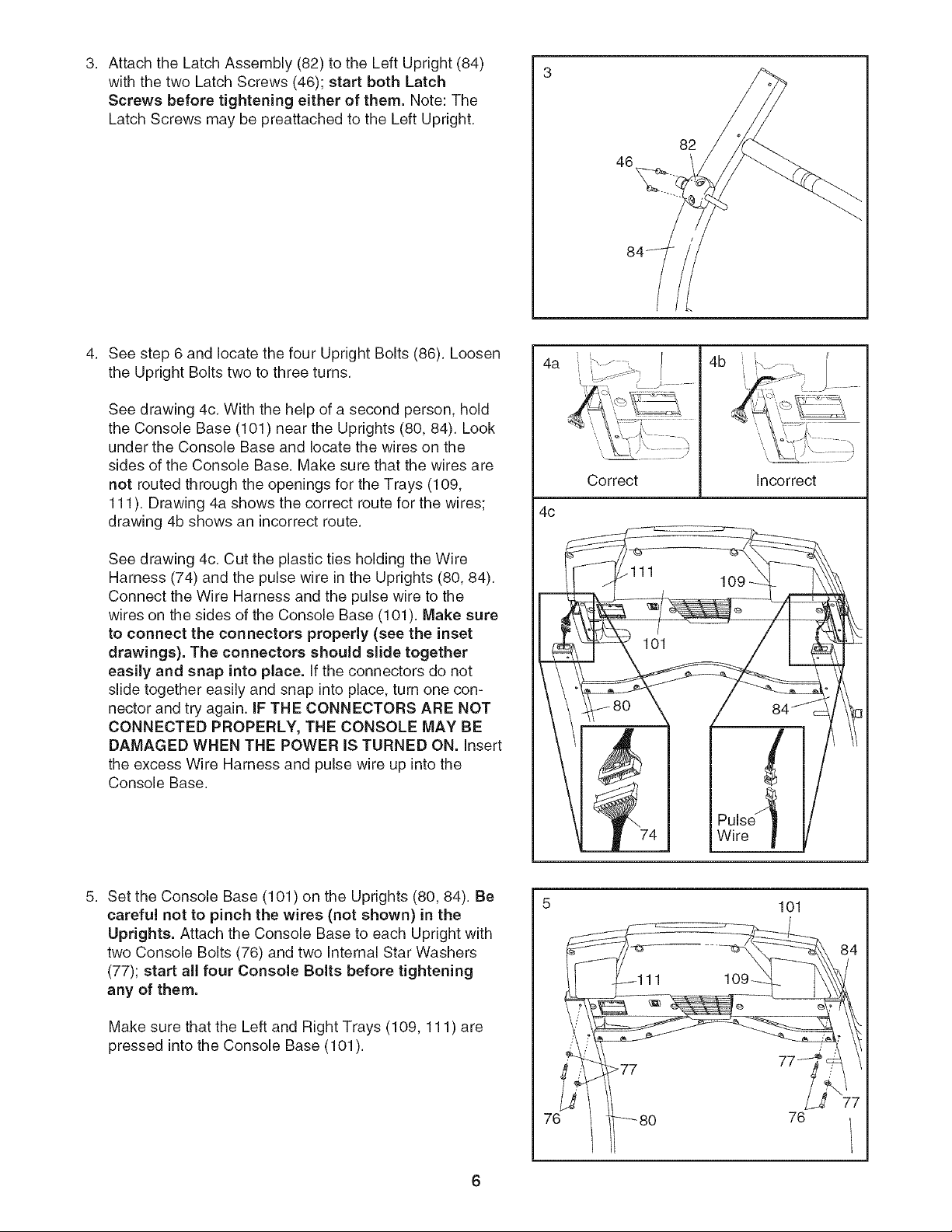
Seestep6andlocatethefourUprightBolts(86).Loosen
theUprightBoltstwotothreeturns.
Seedrawing4c.Withthehelpofasecondperson,hold
theConsoleBase(101)neartheUprights(80,84).Look
undertheConsoleBaseandlocatethewiresonthe
sidesoftheConsoleBase.Makesurethatthewiresare
notroutedthroughtheopeningsfortheTrays(109,
111). Drawing4ashowsthecorrectrouteforthewires;
drawing4bshowsanincorrectroute.
Seedrawing4c.CuttheplastictiesholdingtheWire
Harness(74)andthepulsewireintheUprights(80,84).
ConnecttheWireHarnessandthepulsewiretothe
wiresonthesidesoftheConsoleBase(101).Makesure
to connecttheconnectors properly (see the inset
drawings). The connectors should slide together
easily and snap into place. If the connectors do not
slide together easily and snap into place, turn one con-
nector and try again. IF THE CONNECTORS ARE NOT
CONNECTED PROPERLY, THE CONSOLE MAY BE
DAMAGED WHEN THE POWER IS TURNED ON. insert
the excess Wire Harness and pulse wire up into the
Console Base.
4a
4c
h _ ......
\
Correct
4b !
\
Incorrect
Set the Console Base (101) on the Uprights (80, 84). Be
careful not to pinch the wires (not shown) in the
Uprights. Attach the Console Base to each Upright with
two Console Bolts (76) and two internal Star Washers
(77); start all four Console Bolts before tightening
any of them.
Make sure that the Left and Right Trays (109, 111) are
pressed into the Console Base (101).
76
101
76
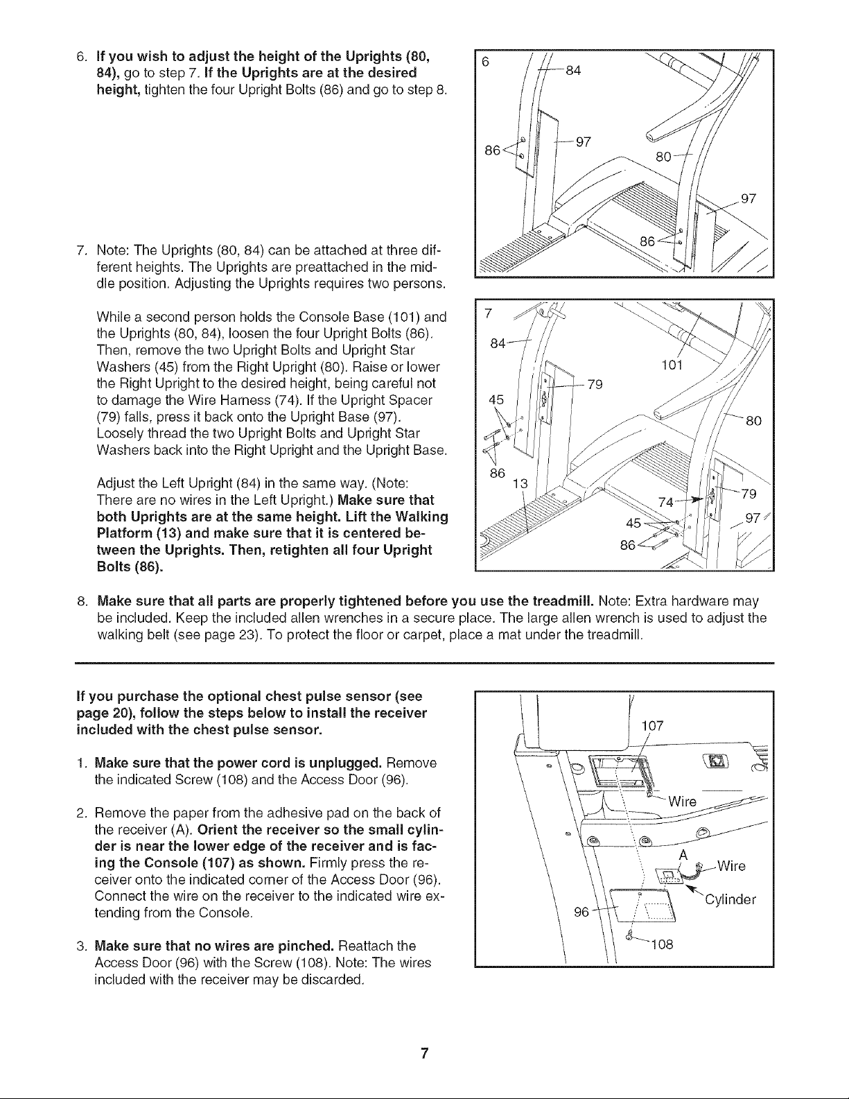
6. If you wish to adjust the height of the Uprights (80,
84), go to step 7. if the Uprights are at the desired
height, tighten the four Upright Bolts (86) and go to step 8.
Note: The Uprights (80, 84) can be attached at three dif-
ferent heights. The Uprights are preattached in the mid-
dle position. Adjusting the Uprights requires two persons.
While a second person holds the Console Base (101 ) and
the Uprights (80, 84), loosen the four Upright Bolts (86).
Then, remove the two Upright Bolts and Upright Star
Washers (45) from the Right Upright (80). Raise or lower
the Right Upright to the desired height, being careful not
to damage the Wire Harness (74). If the Upright Spacer
(79) falls, press it back onto the Upright Base (97).
Loosely thread the two Upright Bolts and Upright Star
Washers back into the Right Upright and the Upright Base.
Adjust the Left Upright (84) in the same way. (Note:
There are no wires in the Left Upright.) Make sure that
both Uprights are at the same height. Lift the Walking
Platform (13) and make sure that it is centered be-
tween the Uprights. Then, retighten all four Upright
Bolts (86).
86 13
8. Make sure that all parts are properly tightened before you use the treadmill. Note: Extra hardware may
be included. Keep the included allen wrenches in a secure place. The large allen wrench is used to adjust the
walking belt (see page 23). To protect the floor or carpet, place a mat under the treadmill.
if you purchase the optional chest pulse sensor (see
page 20), follow the steps below to install the receiver
included with the chest pulse sensor.
1. Make sure that the power cord is unplugged. Remove
the indicated Screw (t 08) and the Access Door (96).
2. Remove the paper from the adhesive pad on the back of
the receiver (A). Orient the receiver so the small cylin-
der is near the lower edge of the receiver and is fac-
ing the Console (107) as shown. Firmly press the re-
ceiver onto the indicated corner of the Access Door (96).
Connect the wire on the receiver to the indicated wire ex-
tending from the Console.
3. Make sure that no wires are pinched. Reattach the
Access Door (96) with the Screw (108). Note: The wires
included with the receiver may be discarded.
107
W ire
OPERATION AND ADJUSTMENT
THE PRE-LUBRICATED WALKING BELT
Your treadmill features a walking belt coated with high-
performance lubricant, iMPORTANT: Never apply sil-
icone spray or other substances to the walking
belt or the walking platform. Such substances will
deteriorate the walking belt and cause excessive
wear.
HOW TO PLUG IN THE POWER CORD
an equipment-grounding conductor and a grounding
plug. Plug the power cord into a surge suppressor,
and plug the surge suppressor into an appropriate
outlet that is properly installed and grounded in
accordance with all local codes and ordinances.
Important: The treadmill is not compatible with
GFCl-equipped outlets.
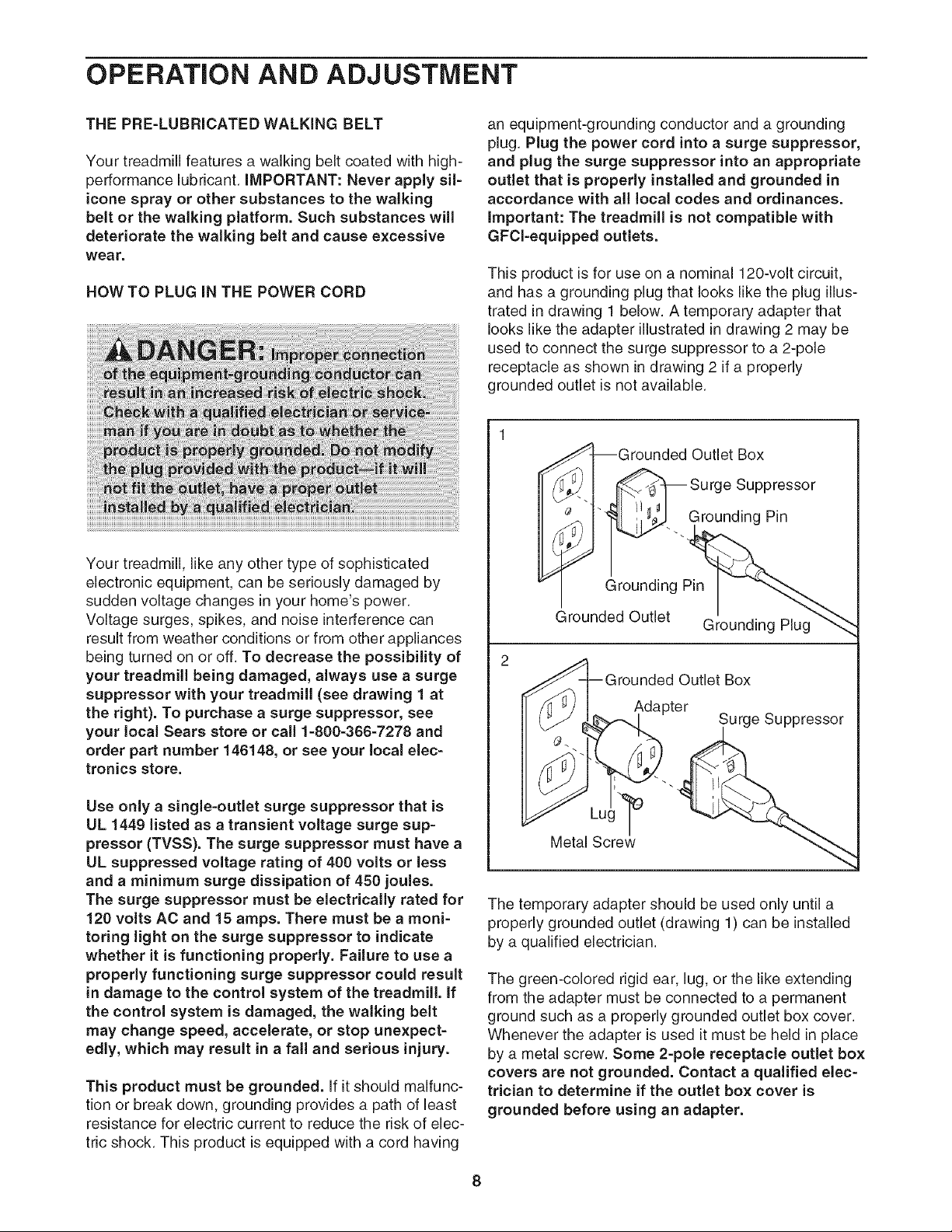
This product is for use on a nominal 120-volt circuit,
and has a grounding plug that looks like the plug illus-
trated in drawing 1 below. A temporary adapter that
looks like the adapter illustrated in drawing 2 may be
used to connect the surge suppressor to a 2-pole
receptacle as shown in drawing 2 if a properly
grounded outlet is not available.
Your treadmill, like any other type of sophisticated
electronic equipment, can be seriously damaged by
sudden voltage changes in your home's power.
Voltage surges, spikes, and noise interference can
result from weather conditions or from other appliances
being turned on or off. To decrease the possibility of
your treadmill being damaged, always use a surge
suppressor with your treadmill (see drawing 1 at
the right). To purchase asurge suppressor, see
your local Sears store or call 1-800-366-7278 and
order part number 146148, or see your local elec-
tronics store.
Use only a single-outlet surge suppressor that is
UL 1449 listed as a transient voltage surge sup-
pressor (TVSS). The surge suppressor must have a
UL suppressed voltage rating of 400 volts or less
and a minimum surge dissipation of 450 joules.
The surge suppressor must be electrically rated for
120 volts AC and 15 amps. There must be a moni-
toring light on the surge suppressor to indicate
whether it is functioning properly. Failure to use a
properly functioning surge suppressor could result
in damage to the control system of the treadmill, if
the control system is damaged, the walking belt
may change speed, accelerate, or stop unexpect-
edly, which may result in a fall and serious injury.
This product must be grounded. If it should malfunc-
tion or break down, grounding provides a path of least
resistance for electric current to reduce the risk of elec-
tric shock. This product is equipped with a cord having
IGrounded Outlet Box
_'4 -- Surge Suppressor
_'< "-. Grounding Pin
Grounding Pin
_rounded Outlet Grounding Plug
2
_rounded Outlet Box
Adapter Surge Suppressor
Metal Screw_ "
The temporary adapter should be used only until a
properly grounded outlet (drawing 1) can be installed
by a qualified electrician.
The green-colored rigid ear, lug, or the like extending
from the adapter must be connected to a permanent
ground such as a properly grounded outlet box cover.
Whenever the adapter is used it must be held in place
by a metal screw. Some 2-pole receptacle outlet box
covers are not grounded. Contact a qualified elec-
trician to determine if the outlet box cover is
grounded before using an adapter.
8
CONSOLEDIAGRAM
)
START STOP
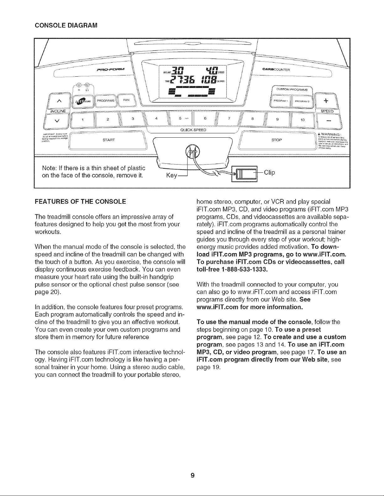
Note: If there is a thin sheet of plastic
on the face of the console, remove it. Key
FEATURES OFTHECONSOLE
The treadmill console offers an impressive array of
features designed to help you get the most from your
workouts.
When the manual mode of the console is selected, the
speed and incline of the treadmill can be changed with
the touch of a button. As you exercise, the console will
display continuous exercise feedback. You can even
measure your heart rate using the built-in handgrip
pulse sensor or the optional chest pulse sensor (see
page 20).
In addition, the console features four preset programs.
Each program automatically controls the speed and in-
cline of the treadmill to give you an effective workout.
You can even create your own custom programs and
store them in memory for future reference
The console also features iFIT.com interactive technol-
ogy. Having iFIT.com technology is like having a per-
sonal trainer in your home. Using a stereo audio cable,
you can connect the treadmill to your portable stereo,
home stereo, computer, or VCR and play special
iFIT.com MP3, CD, and video programs (iFIT.com MP3
programs, CDs, and videocassettes are available sepa-
rately), iFIT.com programs automatically control the
speed and incline of the treadmill as a personal trainer
guides you through every step of your workout; high-
energy music provides added motivation. To down=
load iFIT.com MP3 programs, go to www.iFIT.com.
To purchase iFIT.com CDs or videocassettes, call
toll=free 1=888=533=1333.
With the treadmill connected to your computer, you
can also go to www.iFIT.com and access iFIT.com
programs directly from our Web site. See
www.iFIT.com for more information.
To use the manual mode of the console, follow the
steps beginning on page 10. To use a preset
program, see page 12. To create and use a custom
program, see pages 13 and 14. To use an iFIT.com
MP3, CD, or video program, see page 17. To use an
iFIT.com program directly from our Web site, see
page 19.
HOWTOTURNONTHEPOWER
Pluginthepowercord(seepage8).
Locatethereset/off
circuitbreakernear
thepowercord.Make
surethatthecircuit
breakerisinthereset
position.
On
Position
Stand on the foot rails of the treadmill. Find the clip
attached to the key (see the drawing on page 9)
and slide the clip onto the waistband of your
clothes. Next, route the cord attached to the clip
under the handgrip pulse sensor, and insert the
key into the console. After a moment, the display
will light. Test the clip by carefully taking a few
steps backward until the key is pulled from the
console, if the key is not pulled from the con=
sole, adjust the position of the clip as needed.
HOW TO USE THE MANUAL MODE
Insert the key into the console.
See HOW TO TURN ON THE POWER above.
Select the manual mode.
When the
key is in-
serted, the
manual
mode will
be selected.
If a program
mmmmE
I m
m !
m m
mm_mm
Track
has been selected, reselect the manual mode by
pressing the Programs button repeatedly until a
track appears in the lower part of the display.
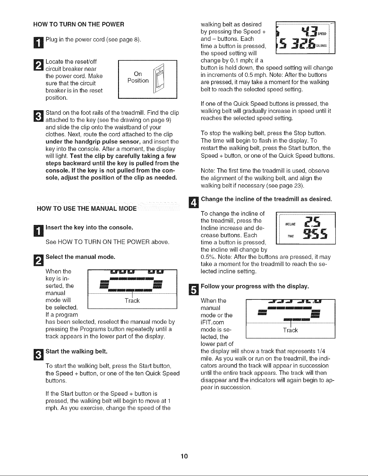
Start the walking belt.
To start the walking belt, press the Start button,
the Speed + button, or one of the ten Quick Speed
buttons.
If the Start button or the Speed + button is
pressed, the walking belt will begin to move at 1
mph. As you exercise, change the speed of the
walking belt as desired
by pressing the Speed +
and - buttons. Each
time a button is pressed,
the speed setting will
change by 0.1 mph; if a
button is held down, the speed setting will change
in increments of 0.5 mph. Note: After the buttons
are pressed, it may take a moment for the walking
belt to reach the selected speed setting.
If one of the Quick Speed buttons is pressed, the
walking belt will gradually increase in speed until it
reaches the selected speed setting.
To stop the walking belt, press the Stop button.
The time will begin to flash in the display. To
restart the walking belt, press the Start button, the
Speed + button, or one of the Quick Speed buttons.
Note: The first time the treadmill is used, observe
the alignment of the walking belt, and align the
walking belt if necessary (see page 23).
Change the incline of the treadmill as desired.
To change the incline of m-_-
the treadmill, press the _ ,NCUME_t_.j
Incline increase and de-
crease buttons. Each TIME _'£ 5
time a button is pressed,
the incline will change by
0.5%. Note: After the buttons are pressed, it may
take a moment for the treadmill to reach the se-
lected incline setting.
Follow your progress with the display.
When the
manual
mode or the
iFIT.com
mode is se-
lected, the
lower part of
mmmmm
m m
m m
m
Track
the display will show a track that represents 1/4
mile. As you walk or run on the treadmill, the indi-
cators around the track will appear in succession
until the entire track appears. The track will then
disappear and the indicators will again begin to ap-
pear in succession.
10
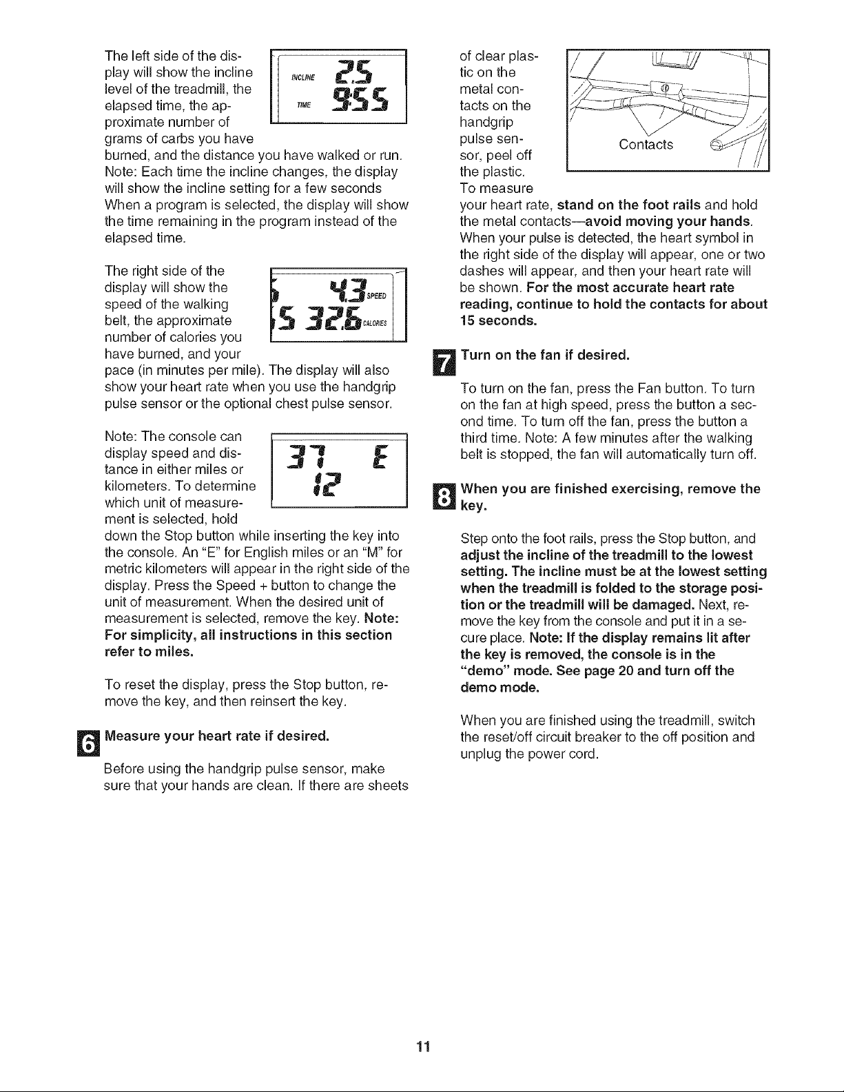
The left side of the dis- r
play will show the incline _CL,N_ _
level of the treadmill, the
elapsed time, the ap- ,,,E _,_:S S
proximate number of
grams of carbs you have
burned, and the distance you have walked or run.
Note: Each time the incline changes, the display
will show the incline setting for a few seconds
When a program is selected, the display will show
the time remaining in the program instead of the
elapsed time.
The right side of the
display will show the
speed of the walking
belt, the approximate
number of calories you
have burned, and your
pace (in minutes per mile). The display will also
show your heart rate when you use the handgrip
pulse sensor or the optional chest pulse sensor.
Note: The console can
display speed and dis-
tance in either miles or
kilometers. To determine
which unit of measure-
ment is selected, hold
down the Stop button while inserting the key into
the console. An "E" for English miles or an "M" for
metric kilometers will appear in the right side of the
display. Press the Speed + button to change the
unit of measurement. When the desired unit of
measurement is selected, remove the key. Note:
For simplicity, all instructions in this section
refer to miles.
To reset the display, press the Stop button, re-
move the key, and then reinsert the key.
Measure your heart rate if desired.
Before using the handgrip pulse sensor, make
sure that your hands are clean. If there are sheets
of clear plas-
tic on the
metal con-
tacts on the
handgrip
pulse sen- Contacts
sor, peel off /
the plastic.
To measure
your heart rate, stand on the foot rails and hold
the metal contacts--avoid moving your hands.
When your pulse is detected, the heart symbol in
the right side of the display will appear, one or two
dashes will appear, and then your heart rate will
be shown. For the most accurate heart rate
reading, continue to hold the contacts for about
15 seconds.
Turn on the fan if desired.
To turn on the fan, press the Fan button. To turn
on the fan at high speed, press the button a sec-
ond time. To turn off the fan, press the button a
third time. Note: A few minutes after the walking
belt is stopped, the fan will automatically turn off.
When you are finished exercising, remove the
key.
Step onto the foot rails, press the Stop button, and
adjust the incline of the treadmill to the lowest
setting. The incline must be at the lowest setting
when the treadmill is folded to the storage posi-
tion or the treadmill will be damaged. Next, re-
move the key from the console and put it in a se-
cure place. Note: if the display remains lit after
the key is removed, the console is in the
"demo" mode. See page 20 and turn off the
demo mode.
When you are finished using the treadmill, switch
the reset/off circuit breaker to the off position and
unplug the power cord.
11
HOW TO USE A PRESET PROGRAM
Insert the key into the console.
See HOW TO TURN ON THE POWER on page
10.
Select one of the four preset programs.
To select
one of the
four preset
programs,
press the
Programs
button re-
peatedly. As
each preset
_ _ PEED
_N
m
mm
Blmm
mmmmBEm
program is selected, the maximum speed setting
of the program and the maximum incline setting of
the program will flash in the display for a few sec-
onds. The display will also show how long the pro-
gram will last. The matrix in the lower part of the
display will show the first seven speed settings of
the program.
Press the Start button or the Speed + button to
start the program.
A moment after the button is pressed, the tread-
mill will automatically adjust to the first speed and
incline settings for the program. Hold the handrails
and begin walking.
Each program is divided into either 20 or 30 one-
minute segments. One speed setting and one in-
cline setting are programmed for each segment.
Note: The same speed setting and/or incline setting
may be programmed for two or more consecutive
segments.
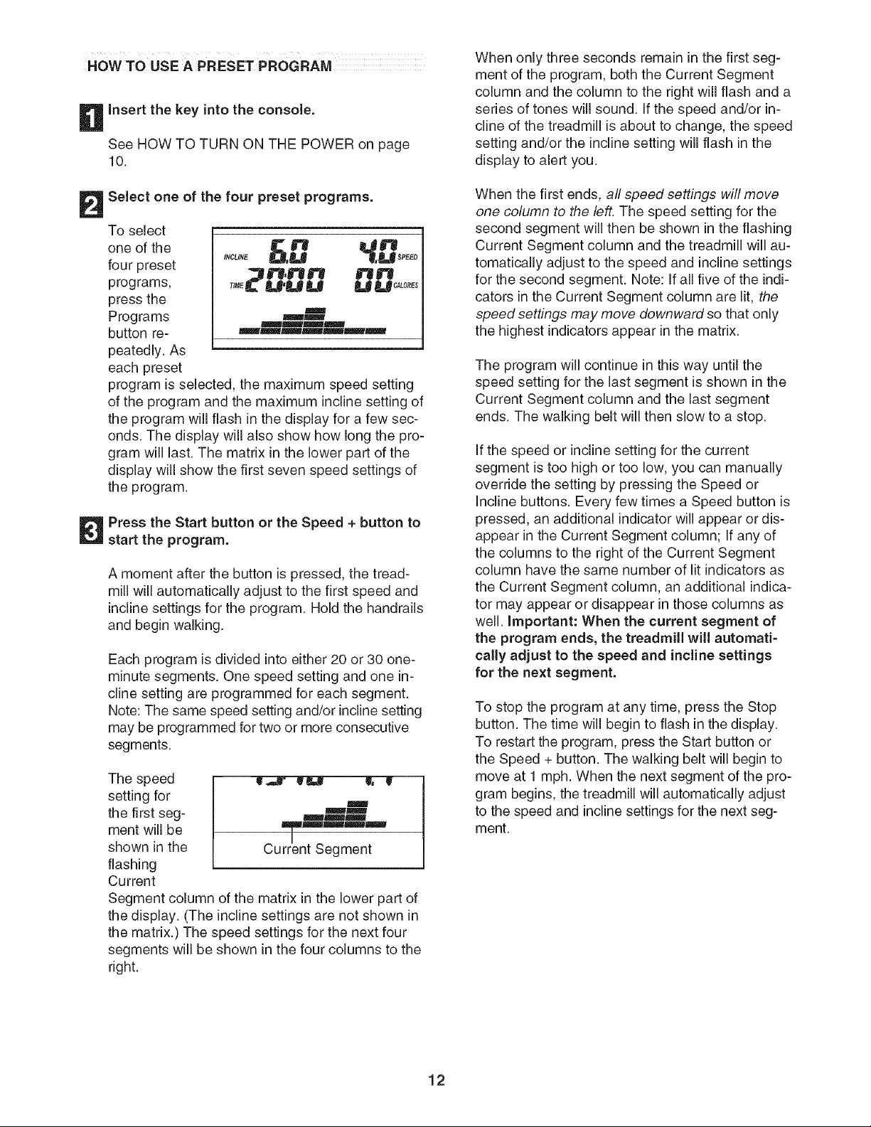
The speed
setting for
the first seg-
ment will be
shown in the
flashing
Current
m
B
mm
mEM
wmmmm
Current Segment
Segment column of the matrix in the lower part of
the display. (The incline settings are not shown in
the matrix.) The speed settings for the next four
segments will be shown in the four columns to the
right.
When only three seconds remain in the first seg-
ment of the program, both the Current Segment
column and the column to the right will flash and a
series of tones will sound. If the speed and/or in-
cline of the treadmill is about to change, the speed
setting and/or the incline setting will flash in the
display to alert you.
When the first ends, all speed settings will move
one column to the left. The speed setting for the
second segment will then be shown in the flashing
Current Segment column and the treadmill will au-
tomatically adjust to the speed and incline settings
for the second segment. Note: If all five of the indi-
cators in the Current Segment column are lit, the
speed settings may move downward so that only
the highest indicators appear in the matrix.
The program will continue in this way until the
speed setting for the last segment is shown in the
Current Segment column and the last segment
ends. The walking belt will then slow to a stop.
If the speed or incline setting for the current
segment is too high or too low, you can manually
override the setting by pressing the Speed or
Incline buttons. Every few times a Speed button is
pressed, an additional indicator will appear or dis-
appear in the Current Segment column; If any of
the columns to the right of the Current Segment
column have the same number of lit indicators as
the Current Segment column, an additional indica-
tor may appear or disappear in those columns as
well. Important: When the current segment of
the program ends, the treadmill will automati-
cally adjust to the speed and incline settings
for the next segment.
To stop the program at any time, press the Stop
button. The time will begin to flash in the display.
To restart the program, press the Start button or
the Speed + button. The walking belt will begin to
move at 1 mph. When the next segment of the pro-
gram begins, the treadmill will automatically adjust
to the speed and incline settings for the next seg-
ment.
12
Follow your progress with the display.
See step 5 on page 10.
Measure your heart rate if desired.
See step 6 on page 11.
Turn on the fan if desired.
See step 7 on page 11.
When you are finished exercising, remove the
key from the console.
When the program has ended, make sure that
the incline of the treadmill is at the lowest set-
ting. Next, remove the key from the console and
put it in a safe place.Note: If the display remains
lit after the key is removed, the console is in
the "demo" mode. See page 20 and turn off the
demo mode.
When you are finished using the treadmill, switch
the reset/off circuit breaker to the off position and
unplug the power cord.
HOWTOCREATECUSTOM PROGRAMS
Insert the key into the console.
See HOW TO TURN ON THE POWER on page
10.
Select one of the custom programs.
To select a
custom pro-
gram, press
the Program
1 or
Program 2
button. The
words "C US-
TOM PRO-
N _ _ ltlsPRE°
tNC_/R_U,U .31,&.al
U JTI,_ N _N
T_ME_U'U U U.U
CUSTOM
_mmBJ_ PROGRAM
GRAM" will appear in the display.
Note: If the custom program has not yet been
defined, only three columns of indicators will
appear in the matrix in the lower part of the
display. If more than three columns of indica-
tors appear, see HOW TO USE CUSTOM PRO=
GRAMS on page 14.
Press the Start button or the Speed +button
and program the desired speed and incline
settings.
A moment after the button is pressed, the walking
belt will begin to move. Hold the handrails and
begin walking.
Refer to the matrix. Each custom program is di-
vided into one-minute segments. One speed set-
ting and one incline setting can be programmed
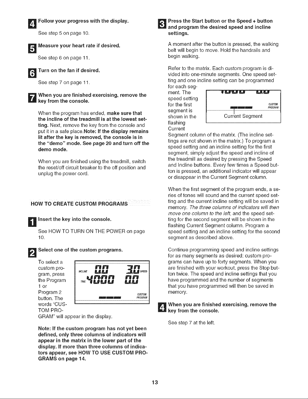
for each seg-
ment. The
speed setting
for the first
segment is
shown in the
flashing
Current
CUSTOM
Segment column of the matrix. (The incline set-
tings are not shown in the matrix.) To program a
speed setting and an incline setting for the first
segment, simply adjust the speed and incline of
the treadmill as desired by pressing the Speed
and Incline buttons. Every few times a Speed but-
ton is pressed, an additional indicator will appear
or disappear in the Current Segment column.
When the first segment of the program ends, a se-
ries of tones will sound and the current speed set-
ting and the current incline setting will be saved in
memory. The three columns of indicators will then
move one column to the left, and the speed set-
ting for the second segment will be shown in the
flashing Current Segment column. Program a
speed setting and an incline setting for the second
segment as described above.
Continue programming speed and incline settings
for as many segments as desired; custom pro-
grams can have up to forty segments. When you
are finished with your workout, press the Stop but-
ton twice. The speed and incline settings that you
have programmed and the number of segments
that you have programmed will then be saved in
memory.
When you are finished exercising, remove the
key from the console.
See step 7 at the left.
13
HOW TO USE CUSTOM PROGRAMS
Insert the key into the console.
See HOW TO TURN ON THE POWER on page
10.
Select one of the custom programs.
To select a
custom pro-
gram, press
the Program
1 or
Program 2
button. The
words
"CUSTOM
INCL_N__,B Sm _SPEED
U
U,U
m
m Emm
JmmmB!
mMBmfmm
PROGRAM" will appear in the display. When a
custom program is selected, the maximum speed
setting of the program and the maximum incline
setting of the program will flash in the display for a
few seconds. The display will also show how long
the program will last. The matrix in the lower part
of the display will show the first seven speed set-
tings of the program. Note: If only three
columns of indicators appear in the matrix,
see HOW TO CREATE A CUSTOM PROGRAM
on page 13.
Press the Start button or the Speed + button to
start the program.
A moment after the button is pressed, the tread-
mill will automatically adjust to the first speed and
incline settings that you programmed previously.
Hold the handrails and begin walking.
Each custom program is divided into several one-
minute segments. One speed setting and one in-
cline setting are programmed for each segment.
(The same speed setting and/or incline setting
may be programmed for two or more consecutive
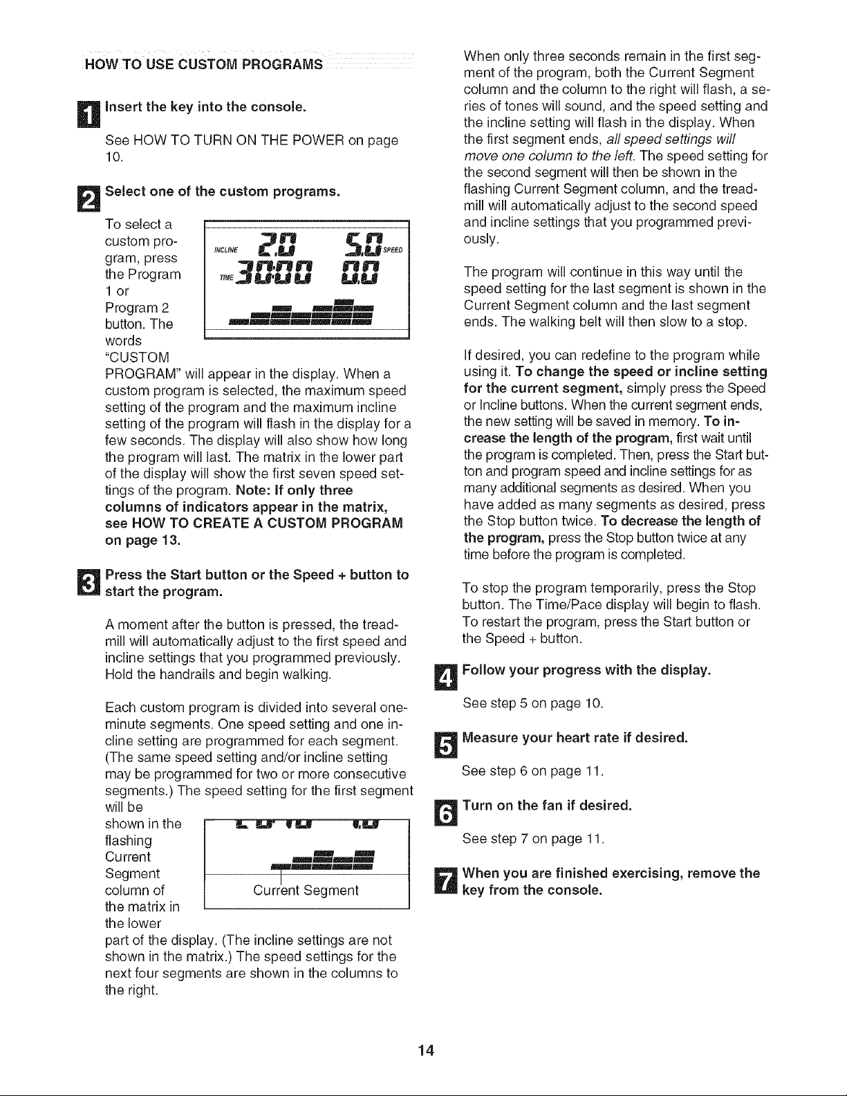
segments.) The speed setting for the first segment
will be
shown in the
flashing
Current ==_ =w
_u=m=_iml
Segment _m====lu==
column of Current Segment
the matrix in
the lower
part of the display. (The incline settings are not
shown in the matrix.) The speed settings for the
next four segments are shown in the columns to
the right.
When only three seconds remain in the first seg-
ment of the program, both the Current Segment
column and the column to the right will flash, a se-
ries of tones will sound, and the speed setting and
the incline setting will flash in the display. When
the first segment ends, all speed settings will
move one column to the left. The speed setting for
the second segment will then be shown in the
flashing Current Segment column, and the tread-
mill will automatically adjust to the second speed
and incline settings that you programmed previ-
ously.
The program will continue in this way until the
speed setting for the last segment is shown in the
Current Segment column and the last segment
ends. The walking belt will then slow to a stop.
If desired, you can redefine to the program while
using it. To change the speed or incline setting
for the current segment, simply press the Speed
or Incline buttons. When the current segment ends,
the new setting will be saved in memory. To in-
crease the length of the program, first wait until
the program is completed. Then, press the Start but-
ton and program speed and incline settings for as
many additional segments as desired. When you
have added as many segments as desired, press
the Stop button twice. To decrease the length of
the program, press the Stop button twice at any
time before the program is completed.
To stop the program temporarily, press the Stop
button. The Time/Pace display will begin to flash.
To restart the program, press the Start button or
the Speed + button.
Follow your progress with the display.
See step 5 on page 10.
Measure your heart rate if desired.
See step 6 on page 11.
Turn on the fan if desired.
See step 7 on page 11.
When you are finished exercising, remove the
key from the console.
14
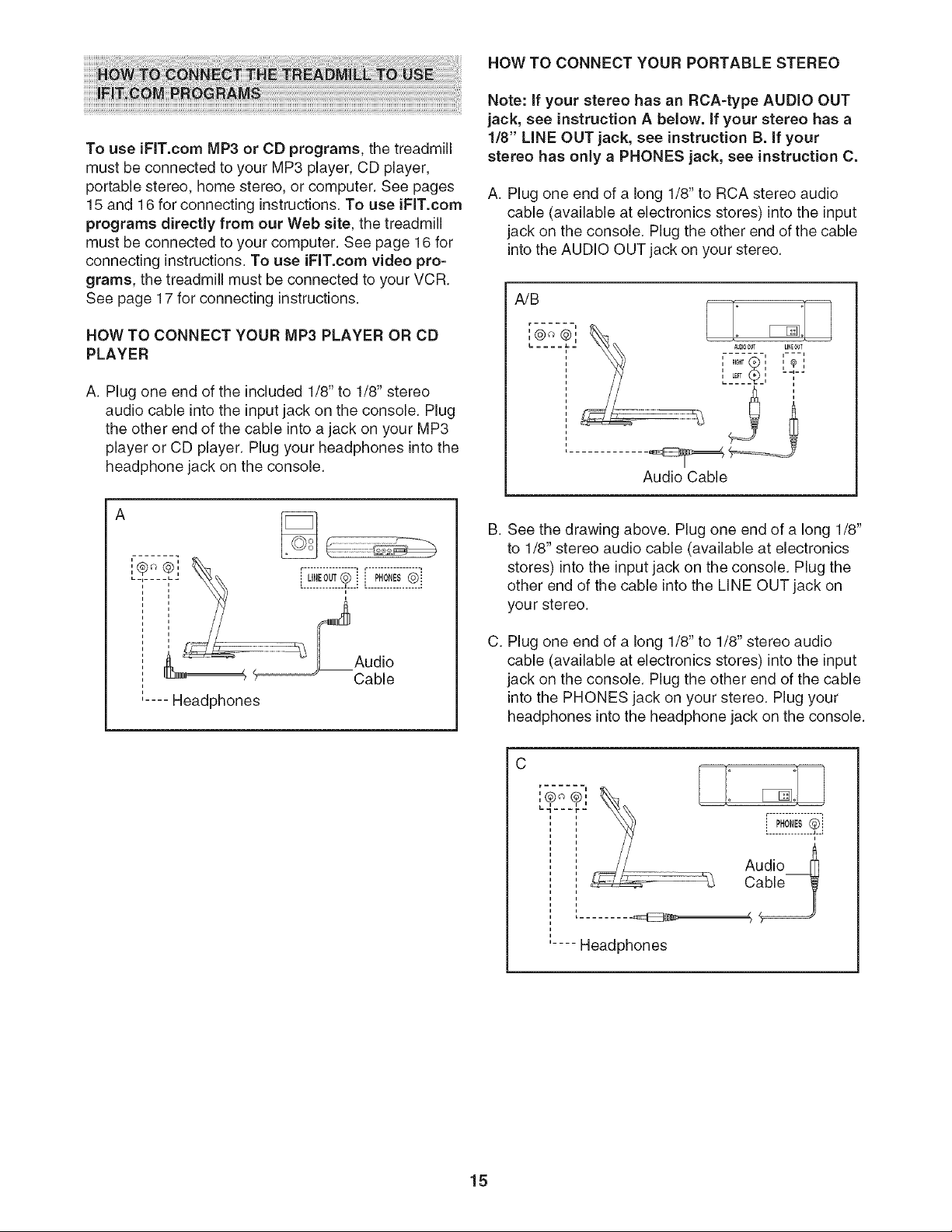
To use iFiT.com MP3 or CD programs, the treadmill
must be connected to your MP3 player, CD player,
portable stereo, home stereo, or computer. See pages
15 and 16 for connecting instructions.To use JFiT.com
programs directly from our Web site, the treadmill
must be connected to your computer. See page 16 for
connecting instructions. To use iFlT.com video pro=
grams, the treadmill must be connected to your VCR.
See page 17 for connecting instructions.
HOW TO CONNECT YOUR MP3 PLAYER OR CD
PLAYER
A. Plug one end of the included 1/8" to 1/8" stereo
audio cable into the input jack on the console. Plug
the other end of the cable into a jack on your MP3
player or CD player. Plug your headphones into the
headphone jack on the console.
,m_ ®, _,_ ......................................
....... ,,'-- L__?__°N_!L®::
i .....................
Audio
U!_4 _'Cable
.... Headphones
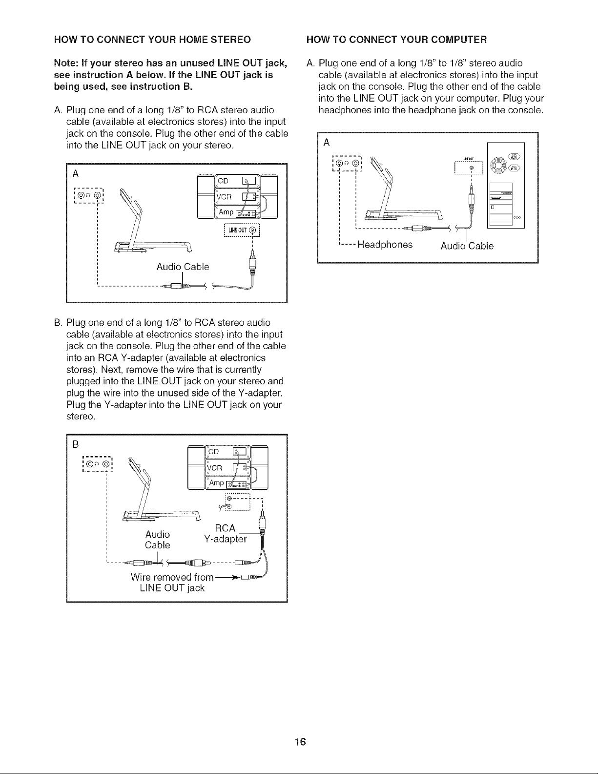
HOW TO CONNECT YOUR PORTABLE STEREO
Note: if your stereo has an RCA-type AUDIO OUT
jack, see instruction A below, if your stereo has a
1/8" LiNE OUT jack, see instruction B. if your
stereo has only a PHONES jack, see instruction C.
A. Plug one end of a long 1/8" to RCA stereo audio
cable (available at electronics stores) into the input
jack on the console. Plug the other end of the cable
into the AUDIO OUT jack on your stereo.
A/B
Audio Cable
B.
C.
See the drawing above. Plug one end of a long 1/8"
to 1/8" stereo audio cable (available at electronics
stores) into the input jack on the console. Plug the
other end of the cable into the LINE OUT jack on
you r stereo.
Plug one end of a long 1/8" to 1/8" stereo audio
cable (available at electronics stores) into the input
jack on the console. Plug the other end of the cable
into the PHONES jack on your stereo. Plug your
headphones into the headphone jack on the console.
r
a ©
,@ @,
Ld---_--
L........
.... Headphones
r................. ,
) PHONES(_::
Audio_
15
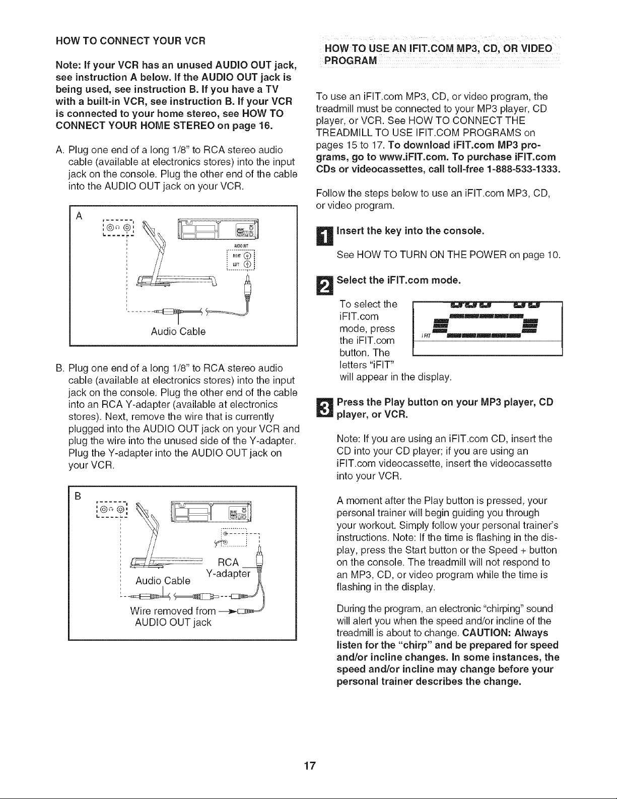
HOW TO CONNECT YOUR HOME STEREO HOW TO CONNECT YOUR COMPUTER
Note: if your stereo has an unused LiNE OUT jack,
see instruction A below. If the LiNE OUT ack is
being used, see instruction B.
A. Plug one end of a long 1/8" to RCA stereo audio
cable (available at electronics stores) into the input
jack on the console. Plug the other end of the cable
into the LINE OUT jack on your stereo.
A
r u
i u
U,EOUT® j
.............. 1....
Audio Cable
A. Plug one end of a long 1/8" to 1/8" stereo audio
cable (available at electronics stores) into the input
jack on the console. Plug the other end of the cable
into the MNE OUT jack on your computer. Plug your
headphones into the headphone jack on the console.
A
,@@, -..............
LJ..... i ? i
........ ......
i
.... Headphones
m
Audio Cable
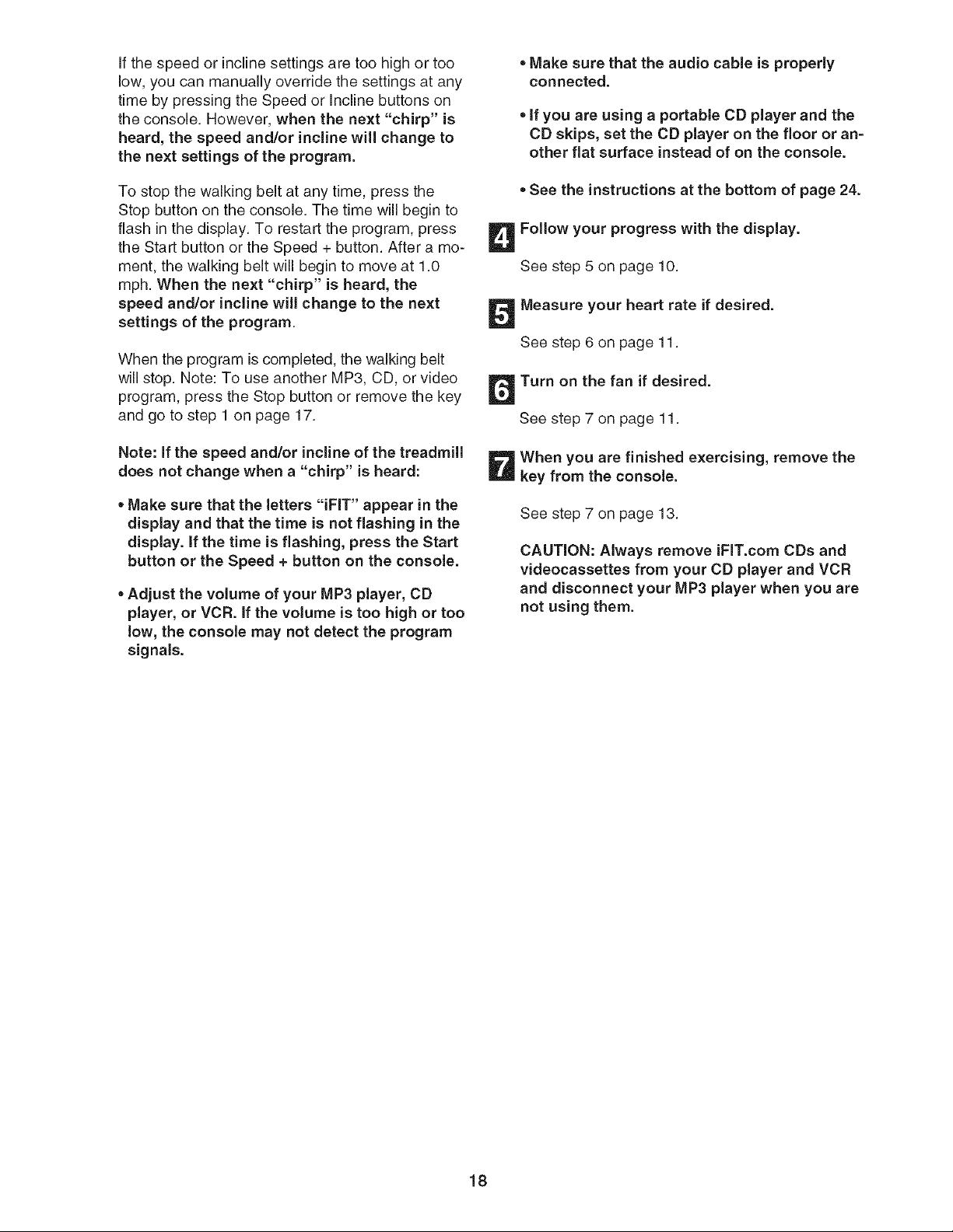
B. Plug one end of a long 1/8" to RCA stereo audio
cable (available at electronics stores) into the input
jack on the console. Plug the other end of the cable
into an RCA Y-adapter (available at electronics
stores). Next, remove the wire that is currently
plugged into the LINE OUT jack on your stereo and
plug the wire into the unused side of the Y-adapter.
Plug the Y-adapter into the MNE OUT jack on your
stereo.
.ico :
L .... j.u
RCA
Audio Y-adapter
Cable
.... _E__ .....
Wire removed from-__
LINE OUT jack
16
HOW TO CONNECT YOUR VCR
Note: if your VCR has an unused AUDIO OUT jack,
see instruction A below, if the AUDIO OUT jack is
being used, see instruction B. if you have aTV
with abuilt=in VCR, see instruction B. if your VCR
is connected to your home stereo, see HOW TO
CONNECT YOUR HOME STEREO on page 16.
A. Plug one end of a long 1/8" to RCA stereo audio
cable (available at electronics stores) into the input
jack on the console. Plug the other end of the cable
into the AUDIO OUT jack on your VCR.
A
r a
L£t2J
Audio Cable
B. Plug one end of a long 1/8" to RCA stereo audio
cable (available at electronics stores) into the input
jack on the console. Plug the other end of the cable
into an RCA Y-adapter (available at electronics
stores). Next, remove the wire that is currently
plugged into the AUDIO OUT jack on your VCR and
plug the wire into the unused side of the Y-adapter.
Plug the Y-adapter into the AUDIO OUT jack on
your VCR.
AUDIO OUT jack
HOW TO USE AN IFHT.COM MP3, CD, OR VIDEO
PROGRAM
To use an iFlT.com MP3, CD, or video program, the
treadmill must be connected to your MP3 player, CD
player, or VCR. See HOW TO CONNECT THE
TREADMILL TO USE (FIT.COM PROGRAMS on
pages 15 to 17. To download iFlT.com MP3 pro-
grams, go to www.iFlT.com. To purchase iFlT.com
CDs or videocassettes, call toll=free 1=888=533=1333.
Follow the steps below to use an iFlT.com MP3, CD,
or video program.
insert the key into the console.
See HOWTO TURN ON THE POWER on page 10.
Select the iFiT.com mode.
To select the
iF(T.com
mode, press
the iFlT.com
button. The
letters "iF(T"
will appear in the display.
mml_mr_mm='/l_m
iFff _m==_mmnmm
Press the Play button on your MP3 player, CD
player, or VCR.
Note: (f you are using an (F(T.com CD, insert the
CD into your CD player; if you are using an
(F(T.com videocassette, insert the videocassette
into your VCR.
A moment after the Play button is pressed, your
personal trainer will begin guiding you through
your workout. Simply follow your personal trainer's
instructions. Note: (f the time is flashing in the dis-
play, press the Start button or the Speed + button
on the console. The treadmill will not respond to
an MP3, CD, or video program while the time is
flashing in the display.
During the program, an electronic "chirping" sound
will alert you when the speed and/or incline of the
treadmill is about to change. CAUTION: Always
listen for the "chirp" and be prepared for speed
and/or incline changes, in some instances, the
speed and/or incline may change before your
personal trainer describes the change.
17
If the speed or incline settings are too high or too
low, you can manually override the settings at any
time by pressing the Speed or Incline buttons on
the console. However, when the next "chirp" is
heard, the speed and/or incline will change to
the next settings of the program.
To stop the walking belt at any time, press the
Stop button on the console. The time will begin to
flash in the display. To restart the program, press
the Start button or the Speed + button. After a mo-
ment, the walking belt will begin to move at 1.0
mph. When the next "chirp" is heard, the
speed and/or incline will change to the next
settings of the program.
When the program is completed, the walking belt
will stop. Note: To use another MP3, CD, or video
program, press the Stop button or remove the key
and go to step 1 on page 17.
Note: If the speed and/or incline of the treadmill
does not change when a "chirp" is heard:
, Make sure that the letters "iFIT" appear in the
display and that the time is not flashing in the
display, if the time is flashing, press the Start
button or the Speed + button on the console.
, Adjust the volume of your MP3 player, CD
player, or VCR. if the volume is too high or too
low, the console may not detect the program
signals.
, Make sure that the audio cable is properly
connected.
, if you are using a portable CD player and the
CD skips, set the CD player on the floor or an-
other fiat surface instead of on the console.
,See the instructions at the bottom of page 24.
Follow your progress with the display.
See step 5 on page 10.
Measure your heart rate if desired.
See step 6 on page 11.
Turn on the fan if desired.
See step 7 on page t t.
When you are finished exercising, remove the
key from the console.
See step 7 on page 13.
CAUTION: Always remove iFIT.com CDs and
videocassettes from your CD player and VCR
and disconnect your MP3 player when you are
not using them.
18
Our Web site at www.iFIT.com allows you to access
basic programs, audio programs, and video programs
directly from the intemet. Additional options are soon to
be available. See www.iFlT.com for details.
To use programs from our Web site, the treadmill must
be connected to your home computer. See HOW TO
CONNECT YOUR COMPUTER on page 16. In
addition, you must have an internet connection and
an internet service provider. A list of specific system re-
quirements is found on our Web site.
Follow the steps below to use a program from our
Web site.
insert the key into the console.
See HOW TO TURN ON THE POWER on page 10.
Select the iFIT.com mode.
To select
the iFlT.com
mode, press
the iFlT.com
button. The
letters "iFIT"
will appear in the display.
_mmm_mmm
i FIT __
Go to your computer and start an internet
connection.
Start your web browser, if necessary, and go to
our Web site at www.iFIT.com.
Follow the desired links on our Web site to se-
lect a program.
Read and follow the on-line instructions for using a
program.
Follow the on-line instructions to start the
program.
When you start the program, an on-screen count-
down will begin.
_ eturn to the treadmill and stand on the foot
rails. Find the clip attached to the key and slide
the clip onto the waistband of your clothes.
When the on-screen countdown ends, the program
will begin and the walking belt will begin to move.
Hold the handrails, step onto the walking belt, and
begin walking. During the program, an electronic
"chirping" sound will alert you when the speed
and/or incline of the treadmill is about to change.
CAUTION: Always listen for the "chirp" and be
prepared for speed and/or incline changes.
If the speed or incline settings are too high or too
low, you can manually override the settings at any
time by pressing the Speed or Incline buttons on
the console. However, when the next "chirp" is
heard, the speed and/or incline will change to
the next settings for the program.
To stop the walking belt at any time, press the
Stop button on the console. The time will begin to
flash in the display. To restart the program, press
the Start button or the Speed + button. After a mo-
ment, the walking belt will begin to move at 1.0
mph. When the next "chirp" is heard, the speed
and incline will change to the next settings of
the program.
When the program is completed, the walking belt
will stop. Note: To use another program, press the
Stop button and go to step 5.
Note: if the speed and/or incline of the treadmill
does not change when a "chirp" is heard, make
sure that the letters "iFIT" appear in the display
and that the time is not flashing in the display.
in addition, make sure that the audio cable is
properly connected.
Follow your progress with the display.
See step 5 on page 10.
When you are finished exercising, remove the
key from the console.
See step 7 on page 13.
19
THE iNFORMATiON MODE/DEMO MODE THE OPTIONAL CHEST PULSE SENSOR
The console features an information mode that keeps
track of the total number of hours that the treadmill has
been operated and the total number of miles that the
walking belt has moved. The information mode also al-
lows you to select miles or kilometers as the unit of
measurement and to turn on and turn off the demo
mode.
To select the information mode, hold down the Stop
button while inserting the key into the console. When
the information mode is selected, the following informa-
tion will be shown in the display:
The left side of the display
will show the total number of
miles (or kilometers) that the
walking belt has moved and
the total number of hours
that the treadmill has been
E
M,e' t --Hours
used. An "E" for english miles or an "M" for metric kilo-
meters will appear in the right side of the display. Press
the Speed + button to change the unit of measurement.
iMPORTANT: If a "d" appears in the right side of the
display, the console is in the "demo" mode. This mode
is intended to be used only when a treadmill is dis-
played in a store. When the console is in the demo
mode, the power cord can be plugged in, the key can
be removed from the console, and the indicators in the
display will automatically appear in a preset sequence,
although the buttons on the console will not operate, if a
"d" appears when the information mode is selected,
press the Speed - button so "d" disappears.
To exit the information mode, remove the key from the
console.
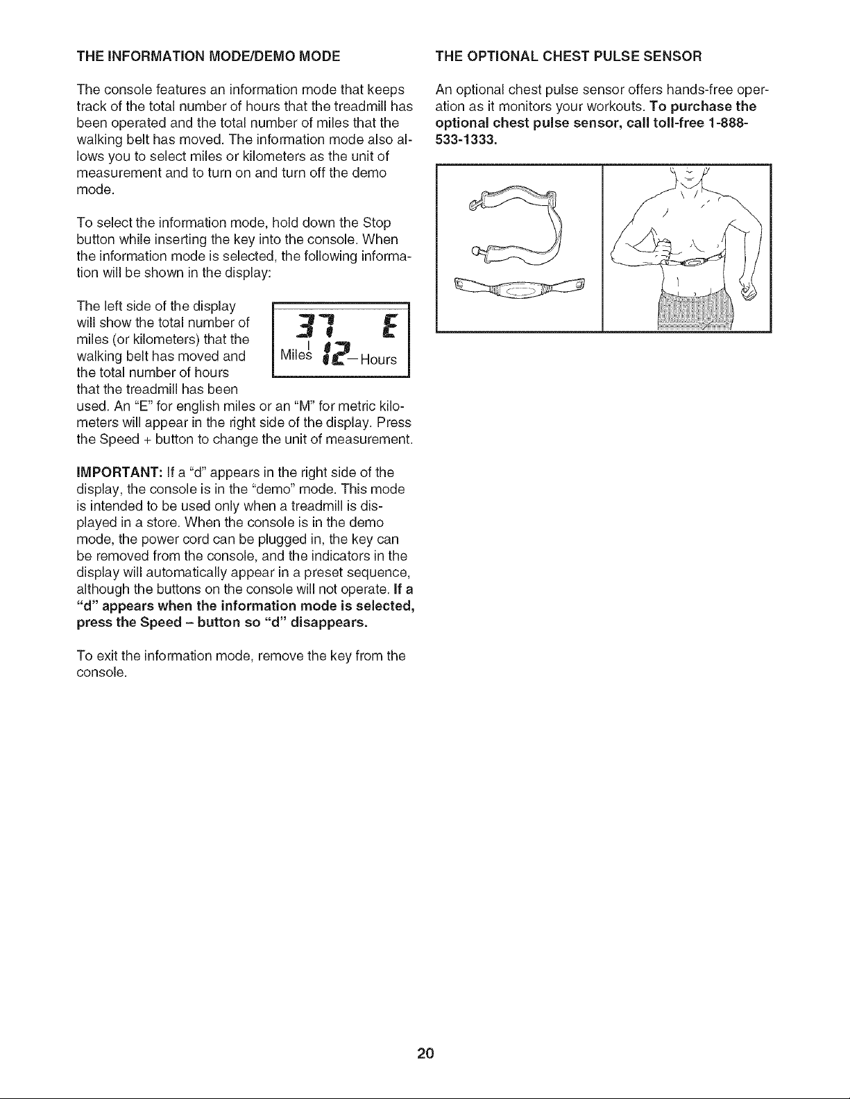
An optional chest pulse sensor offers hands-free oper-
ation as it monitors your workouts. To purchase the
optional chest pulse sensor, call toll-free 1-888-
533-1333.
2O
HOW TO FOLD AND MOVE THE TREADMILL
NOW TO FOLD THE TREADMILL FOR STORAGE
Before folding the treadmill, adjust the incline to the
lowest position. If this is not done, the treadmill may be per-
manently damaged. Next, unplug the power cord. CAUTION:
You must be able to safely lift 45 pounds (20 kg) to raise,
lower, or move the treadmill.
1. Hold the treadmill with your hands inthe locations shown at the
right. To decrease the possibility of injury, bend your legs
and keep your back straight. As you raise the treadmill,
make sure to lift with your legs rather than your back.
Raise the treadmill about halfway to the vertical position.
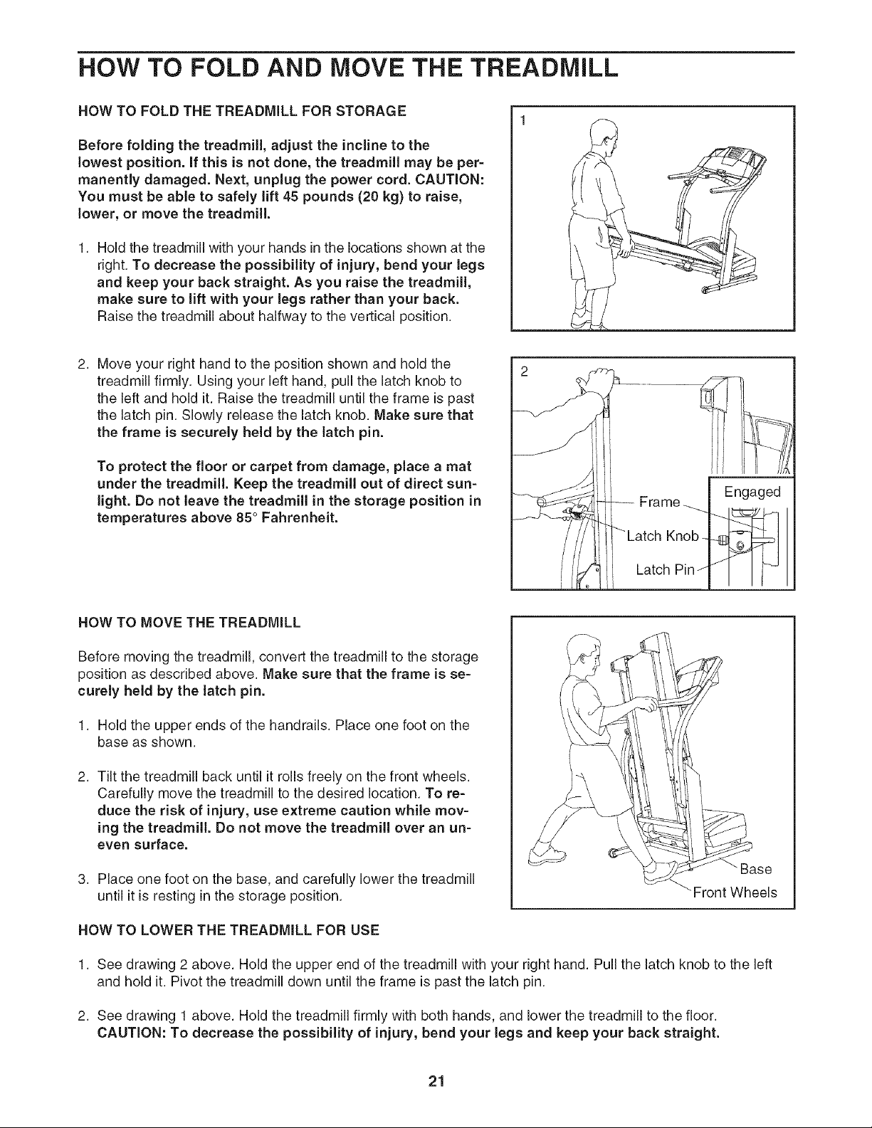
2. Move your right hand to the position shown and hold the
treadmill firmly. Using your left hand, pull the latch knob to
the left and hold it. Raise the treadmill until the frame is past
the latch pin. Slowly release the latch knob. Make sure that
the frame is securely held by the latch pin.
To protect the floor or carpet from damage, place a mat
under the treadmill. Keep the treadmill out of direct sun-
light. Do not leave the treadmill in the storage position in
temperatures above 85 ° Fahrenheit.
Frame
Knob
Latch Pin /
Engaged
HOW TO MOVE THE TREADMILL
Before moving the treadmill, convert the treadmill to the storage
position as described above. Make sure that the frame is se-
curely held by the latch pin.
1. Hold the upper ends of the handrails. Place one foot on the
base as shown.
2. Tilt the treadmill back until it rolls freely on the front wheels.
Carefully move the treadmill to the desired location. To re-
duce the risk of injury, use extreme caution while mov-
ing the treadmill. Do not move the treadmill over an un-
even surface.
3. Place one foot on the base, and carefully lower the treadmill
until it is resting in the storage position.
_se
•Front Wheels
HOW TO LOWER THE TREADMILL FOR USE
1. See drawing 2 above. Hold the upper end of the treadmill with your right hand. Pull the latch knob to the left
and hold it. Pivot the treadmill down until the frame is past the latch pin.
2. See drawing 1 above. Hold the treadmill firmly with both hands, and lower the treadmill to the floor.
CAUTION: To decrease the possibility of injury, bend your legs and keep your back straight.
21
TROUBLESHOOTING
Most treadmill problems can be solved by following the simple steps below. Find the symptom that
applies, and follow the steps listed, if further assistance is needed, call toll=free 1-800-4-MY-HOME ®
(1-800-469-4663).
PROBLEM: The power does not turn on
Make sure that the power cord is plugged into a surge suppressor, and that the surge suppressor
is plugged into a properly grounded outlet (see page 8). Use only a single-outlet surge suppressor
that meets all of the specifications described on page 8. Important: The treadmill is not compatible
with GFCl-equipped outlets.
SOLUTION: a.
b,
C.
After the power cord has been plugged in, make sure that the key is fully inserted into the console.
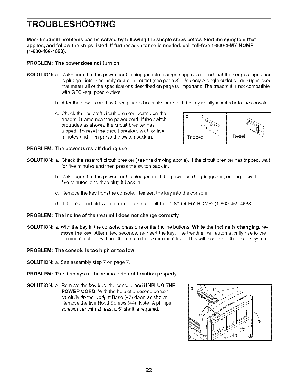
Check the reset/off circuit breaker located on the
treadmill frame near the power cord. If the switch
protrudes as shown, the circuit breaker has
tripped. To reset the circuit breaker, wait for five
minutes and then press the switch back in.
PROBLEM: The power turns off during use
Tripped Reset
SOLUTION: a. Check the reset/off circuit breaker (see the drawing above). If the circuit breaker has tripped, wait
for five minutes and then press the switch back in.
b. Make sure that the power cord is plugged in. If the power cord is plugged in, unplug it, wait for
five minutes, and then plug it back in.
c. Remove the key from the console. Reinsert the key into the console.
d. If the treadmill still will not run, please call toll-free 1-800-4-MY-HOME _ (1-800-469-4663).
PROBLEM: The incline of the treadmill does not change correctly
SOLUTION: a. With the key in the console, press one of the Incline buttons. While the incline is changing, re-
move the key. After a few seconds, re-insert the key. The treadmill will automatically rise to the
maximum incline level and then return to the minimum level. This will recalibrate the incline system.
PROBLEM: The console is too high or too low
SOLUTION: a. See assembly step 7 on page 7.
PROBLEM: The displays of the console do not function properly
SOLUTION: a. Remove the key from the console and UNPLUG THE
POWER CORD. With the help of a second person,
carefully tip the Upright Base (97) down as shown.
Remove the five Hood Screws (44). Note: A phillips
screwdriver with at least a 5" shaft is required.
\
44
22
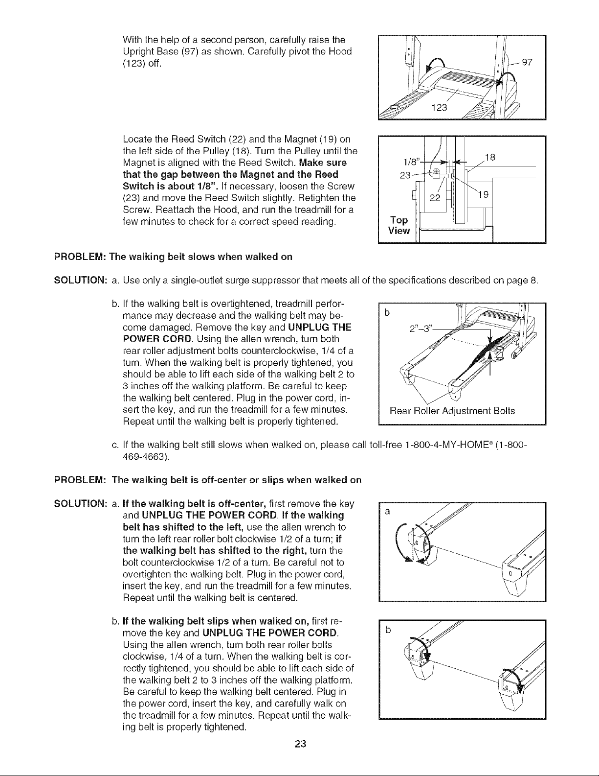
With the help of a second person, carefully raise the
Upright Base (97) as shown. Carefully pivot the Hood
(123) off.
Locate the Reed Switch (22) and the Magnet (19) on
the left side of the Pulley (18). Turn the Pulley until the
Magnet is aligned with the Reed Switch. Make sure
that the gap between the Magnet and the Reed
Switch is about 1/8". If necessary, loosen the Screw
(23) and move the Reed Switch slightly. Retighten the
Screw. Reattach the Hood, and run the treadmill for a
few minutes to check for a correct speed reading.
97
PROBLEM: The walking belt slows when walked on
SOLUTION: a. Use only a single-outlet surge suppressor that meets all of the specifications described on page 8.
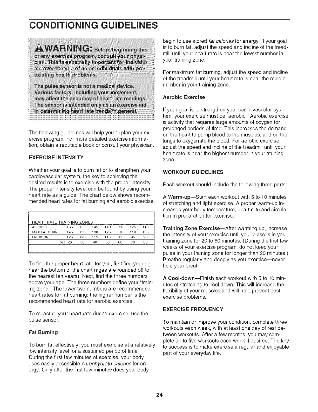
b, If the walking belt is overtightened, treadmill perfor-
mance may decrease and the walking belt may be-
come damaged. Remove the key and UNPLUG THE
POWER CORD. Using the allen wrench, turn both
rear roller adjustment bolts counterclockwise, 1/4 of a
turn. When the walking belt is properly tightened, you
should be able to lift each side of the walking belt 2 to
3 inches off the walking platform. Be careful to keep
the walking belt centered. Plug in the power cord, in-
sert the key, and run the treadmill for a few minutes.
Repeat until the walking belt is properly tightened.
Rear Roller Adjustment Bolts
c. If the walking belt still slows when walked on, please call toll-free 1-800-4-MY-HOME _ (1-800-
469-4663).
PROBLEM: The walking belt is off-center or slips when walked on
SOLUTION: a. If the walking belt is off-center, first remove the key
and UNPLUG THE POWER CORD. If the walking
belt has shifted to the left, use the allen wrench to
turn the left rear roller bolt clockwise 1/2 of a turn; if
the walking belt has shifted to the right, turn the
bolt counterclockwise 1/2 of a turn. Be careful not to
overtighten the walking belt. Plug in the power cord,
insert the key, and run the treadmill for a few minutes.
Repeat until the walking belt is centered.
b, if the walking belt slips when walked on, first re-
move the key and UNPLUG THE POWER CORD.
Using the allen wrench, turn both rear roller bolts
clockwise, 1/4 of a turn. When the walking belt is cor-
rectly tightened, you should be able to lift each side of
the walking belt 2 to 3 inches off the walking platform.
Be careful to keep the walking belt centered. Plug in
the power cord, insert the key, and carefully walk on
the treadmill for a few minutes. Repeat until the walk-
ing belt is properly tightened.
23
CONDiTiONiNG GUiDELiNES
begin to use stored fat calories for energy. If your goal
is to burn fat, adjust the speed and incline of the tread-
mill until your heart rate is near the lowest number in
your training zone.
For maximum fat burning, adjust the speed and incline
of the treadmill until your heart rate is near the middle
number in your training zone.
Aerobic Exercise
If your goal is to strengthen your cardiovascular sys-
tem, your exercise must be "aerobic." Aerobic exercise
is activity that requires large amounts of oxygen for
The following guidelines will help you to plan your ex-
ercise program. For more detailed exercise informa-
tion, obtain a reputable book or consult your physician.
EXERCISE iNTENSiTY
prolonged periods of time. This increases the demand
on the heart to pump blood to the muscles, and on the
lungs to oxygenate the blood. For aerobic exercise,
adjust the speed and incline of the treadmill until your
heart rate is near the highest number in your training
zone.
Whether your goal is to burn fat or to strengthen your
cardiovascular system, the key to achieving the
desired results is to exercise with the proper intensity.
The proper intensity level can be found by using your
heart rate as a guide. The chart below shows recom-
mended heart rates for fat burning and aerobic exercise.
HEART RATE TRAINING ZONES
AEROBIC 165 155 145 140 130 125 115
MAX FAT BURN 145 138 130 125 118 110 103
FAT BURN 125 120 115 110 105 95 90
Age 20 30 40 50 60 70 80
To find the proper heart rate for you, first find your age
near the bottom of the chart (ages are rounded off to
the nearest ten years). Next, find the three numbers
above your age. The three numbers define your "train-
ing zone." The lower two numbers are recommended
heart rates for fat burning; the higher number is the
recommended heart rate for aerobic exercise.
To measure your heart rate during exercise, use the
pulse sensor.
Fat Burning
To burn fat effectively, you must exercise at a relatively
low intensity level for a sustained period of time.
During the first few minutes of exercise, your body
uses easily accessible carbohydrate calories for en-
ergy. Only after the first few minutes does your body
WORKOUT GUiDELiNES
Each workout should include the following three parts:
AWarm=up--Start each workout with 5 to 10 minutes
of stretching and light exercise. A proper warm-up in-
creases your body temperature, heart rate and circula-
tion in preparation for exercise.
Training Zone Exercise--After warming up, increase
the intensity of your exercise until your pulse is in your
training zone for 20 to 60 minutes. (During the first few
weeks of your exercise program, do not keep your
pulse in your training zone for longer than 20 minutes.)
Breathe regularly and deeply as you exercise--never
hold your breath.
ACool=down--Finish each workout with 5 to 10 min-
utes of stretching to cool down. This will increase the
flexibility of your muscles and will help prevent post-
exercise problems.
EXERCISEFREQUENCY
To maintain or improve your condition, complete three
workouts each week, with at least one day of rest be-
tween workouts. After a few months, you may com-
plete up to five workouts each week if desired. The key
to success is to make exercise a regular and enjoyable
part of your everyday life.
24
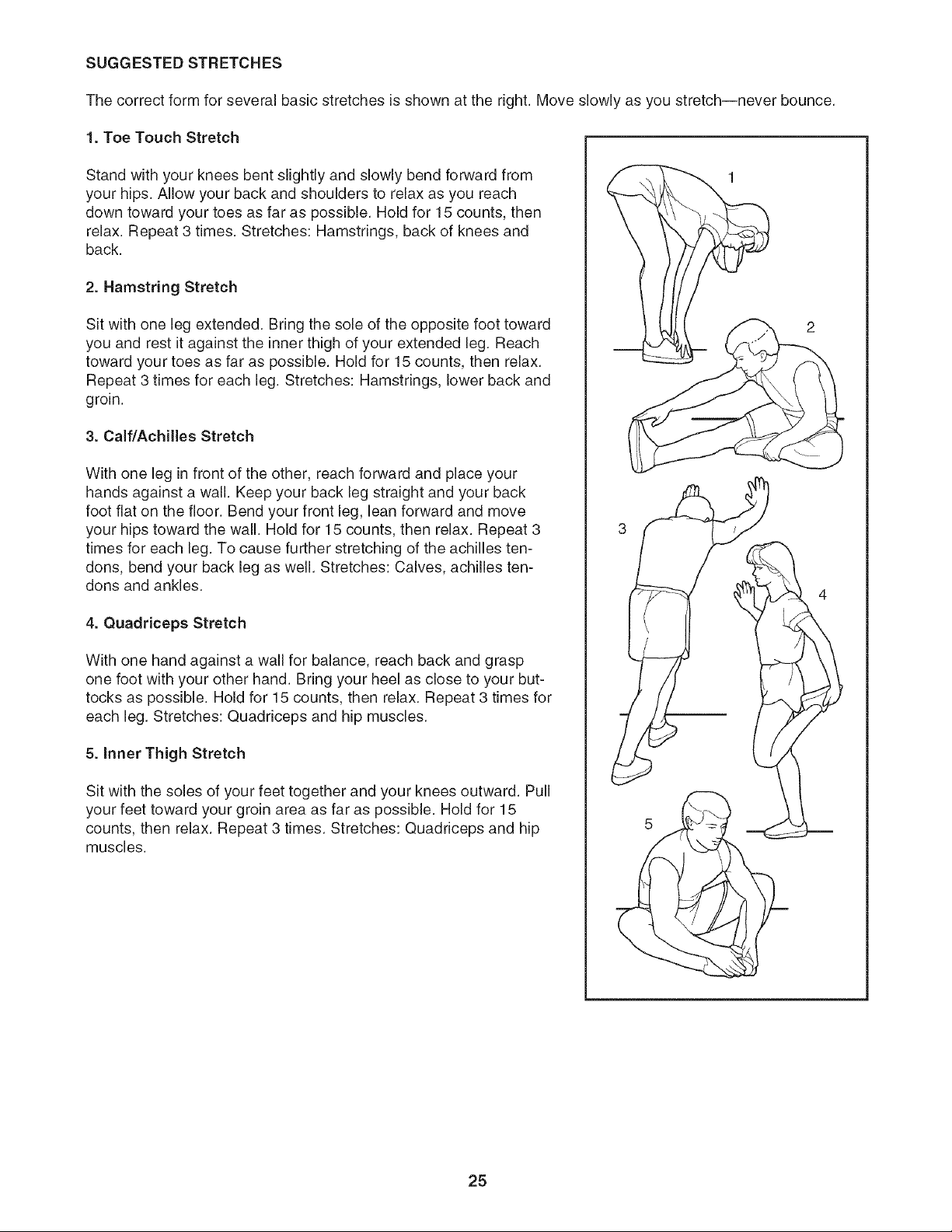
SUGGESTED STRETCHES
The correct form for several basic stretches is shown at the right. Move slowly as you stretch--never bounce.
1. Toe Touch Stretch
Stand with your knees bent slightly and slowly bend forward from
your hips. Allow your back and shoulders to relax as you reach
down toward your toes as far as possible. Hold for 15 counts, then
relax. Repeat 3 times. Stretches: Hamstrings, back of knees and
back.
2. Hamstring Stretch
Sit with one leg extended. Bring the sole of the opposite foot toward
you and rest it against the inner thigh of your extended leg. Reach
toward your toes as far as possible. Hold for 15 counts, then relax.
Repeat 3 times for each leg. Stretches: Hamstrings, lower back and
groin.
3. Calf/Achilles Stretch
With one leg in front of the other, reach forward and place your
hands against a wall. Keep your back leg straight and your back
foot flat on the floor. Bend your front leg, lean forward and move
your hips toward the wall. Hold for 15 counts, then relax. Repeat 3
times for each leg. To cause further stretching of the achilles ten-
dons, bend your back leg as well. Stretches: Calves, achilles ten-
dons and ankles.
4. Quadriceps Stretch
With one hand against a wall for balance, reach back and grasp
one foot with your other hand. Bring your heel as close to your but-
tocks as possible. Hold for 15 counts, then relax. Repeat 3 times for
each leg. Stretches: Quadriceps and hip muscles.
5. Inner Thigh Stretch
Sit with the soles of your feet together and your knees outward. Pull
your feet toward your groin area as far as possible. Hold for 15
counts, then relax. Repeat 3 times. Stretches: Quadriceps and hip
muscles.
25

PART LiST--Model No. 831.295251 RttO4A
To locate the parts listed below, see the EXPLODED DRAWING attached in the center of this manual.
Key No. Qty. Description Key No. Qty. Description
1 1 Left Foot Rail 51 2 Static Decal
2 12 Foot Rail Screw 52 10 3/4" Tek Screw
3 2 Isolator Bolt (Top) 53 3 Belly Pan Clip
4 2 isolator Decal 54 1 Belly Pan
5 2 isolator Top Cap 55 1 Releasable Tie
6 2 Front isolator 56 1 Photo Switch Wire
7 2 isolator 57 1 Tie Holder Clamp
8 2 isolator Bottom Cap 58 1 Cable Tie
9 2 isolator Bracket Cover 59 1 Frame
10 2 isolator Bracket 60 1 Right Rear Foot
11 4 Isolator Bracket Bolt 61 1 Motor Bracket
12 2 isolator Bolt 62 2 Rear Roller Adj, Bolt
13 1 Walking Platform 63 1 Rear Roller
14 2 Belt Guide 64 1 Allen Wrench
15 4 Belt Guide Screw 65 1 5/32" Allen Wrench
16 2 Walking Platform Screw (Rear) 66 1 Left Rear Foot
17 2 Frame Pivot Bolt 67 1 Right Foot Rail
18 1 Front Roller/Pulley 68 1 Walking Belt
19 1 Magnet 69 2 Warning Decal
20 8 Pivot Nut 70 1 Filter Wire
21 2 Pivot Bushing 71 1 Pulse Bar
22 1 Reed Switch 72 1 Cotter Pin
23 1 Reed Switch Screw 73 1 Photo Switch Star Washer
24 1 Reed Switch Clip 74 1 Wire Harness
25 1 Motor Tension Bolt/Lift Pivot 75 1 Right Top Endcap
26 1 Motor Tension Washer 76 4 Upright Bolt
27 1 Pulley/Flywheel/Fan 77 4 internal Star Washer
28 1 Motor Pulley 78 2 Front Isolator Screw
29 1 Motor Star Washer 79 2 Upright Spacer
30 1 Motor Tension Nut 80 1 Right Upright
31 1 Drive Motor 81 1 Right Top Endcap
32* 1 Motor Assembly 82 1 Latch Assembly
33 1 Lift Frame 83 1 Controller Wire
34 1 Right Handrail 84 1 Left Upright
35 2 Walking Platform Nut 85 2 Upright Endcap
36 1 Motor Pivot Bolt 86 4 Upright Bolt
37 1 Incline Motor 87 8 U-nut
38 2 incline Motor Bolt 88 2 Upright Endcap (Lower)
39 6 1/4" Washer 89* 2 Extension Leg Assembly
40 4 1" Tek Screw 90 2 Wheel Bolt
41 1 Front Roller Adj. Bolt 91 2 Warning Decal
42 2 Walking Platform Screw (Front) 92 2 Extension Leg
43 1 Choke 93 1 Console Back
44 5 Hood Screw 94 2 Wheel
45 6 Star Washer 95 2 Controller Screw
46 2 Latch Screw 96 1 Access Door
47 1 Reset/Off Circuit Breaker 97 1 Upright Base
48 1 Controller 98 1 Photo Switch
49 1 Power Cord 99 4 Base Pad
50 1 Power Cord Grommet 100 2 Upright Base Endcap
26
Key No. Qty. Description Key No. Qty. Description
101 1 Console Base 118
102 1 Optic Disk 119
103 8 Ground Screw/Choke Screw 120
104 1 Key Clip 121
105 2 Fan Screw #
106 1 Fan #
107 1 Console #
108 44 Screw #
109 1 Left Tray #
110 1 Console Support #
111 1 Right Tray #
112 1 iFIT.com Wire #
113 1 Hood
114 2 Motor Bracket Bolt
115 1 Photo Switch Screw
116 1 Left Handrail
117 1 Left Top Handgrip
1
1
1
1
1
1
1
1
1
1
1
1
Photo Switch Nut
Left Bottom Handgrip
Right Top Handgrip
Right Bottom Handgrip
10" Blue Wire, 2F
10" Blue Wire, M/F
4" Blue Wire, M/F
8" Green Wire, 2 Ring
4" Green Wire, M/Ring
14" Red Wire, M/F
12" Black Wire, M/F
User's Manual
*Includes all parts shown in the box
#These parts are not illustrated
If a part is missing, call toll-free 1-888-533-1333.
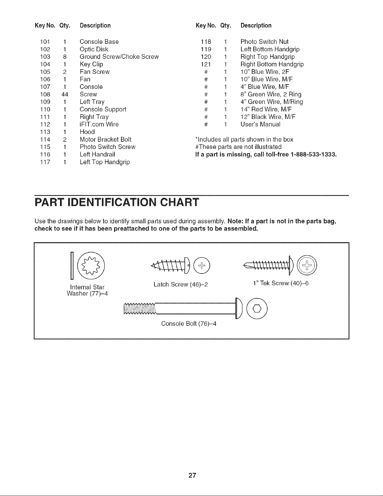
PART IDENTIFICATION CHART
Use the drawings below to identify small parts used during assembly. Note: If a part is not in the parts bag,
check to see if it has been preattached to one of the parts to be assembled.
Internal Star
Washer (77)-4
Latch Screw (46)-2 1" Tek Screw (40)-6
Console Bolt (76)-4
27
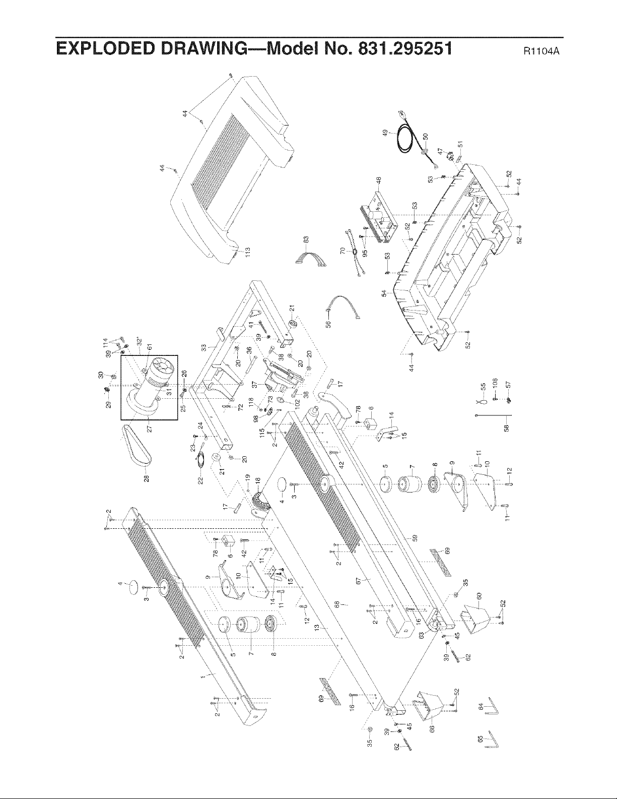
EXPLODED DRAWING--iVlodei No. 831.295251 m_o4A
/
\
/
I
i
\\
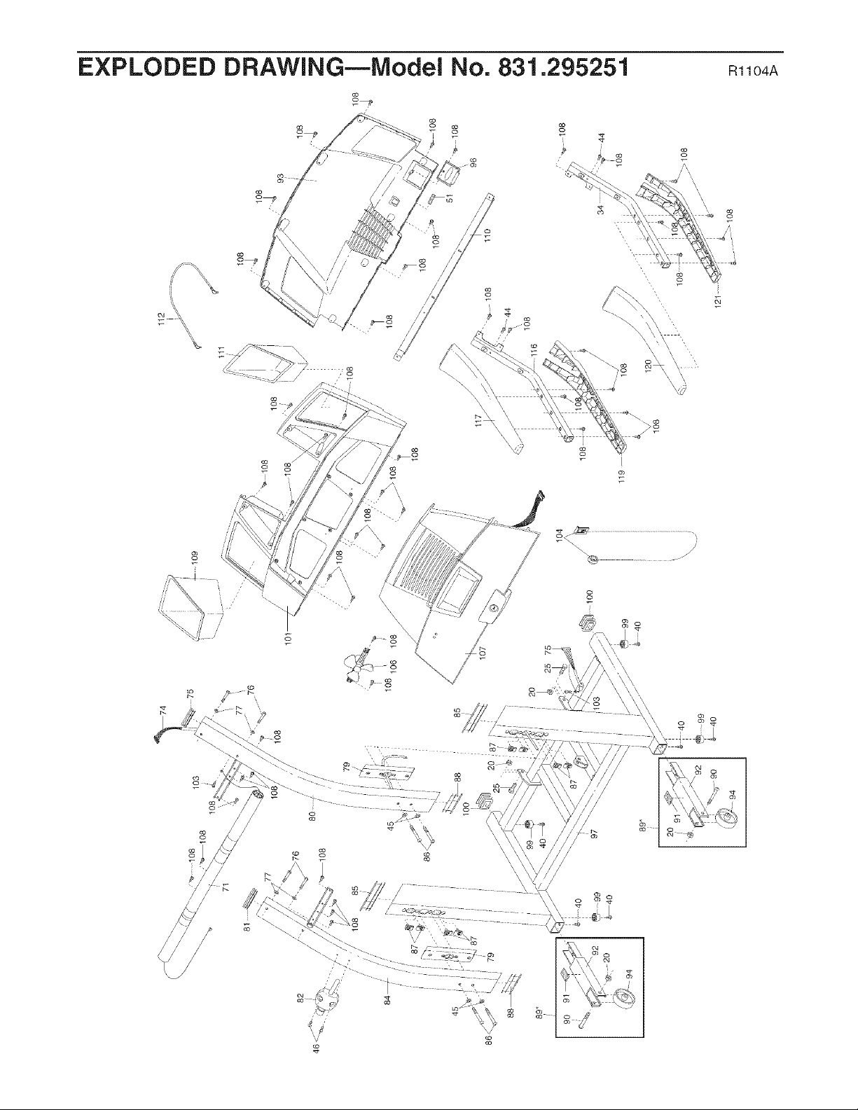
EXPLODED DRAWING--iVlodei No. 831.295251 m_o4A
co
2_
i
\
\ _ \\
I
\\
\\\\
\\
/
/
\
/
/
/
/
/
/
/
/
/
/
'_ o $$
V

Your Home
For repair - in your home - of all major brand appliances, lawn and garden equipment,
or heating and cooling systems, no matter who made it, no matter who sold it!
For the replacement parts, accessories, and user's manuals that you need to do-it-yourself.
For Sears professional installation of home appliances
and items like garage door openers and water heaters.
1-800-4-MY-HOME ® Anytime, day or night
(1-800-469-4663) (U.S.A. and Canada)
www.sears.com www.sears.ca
Our Home
For repair of carry-in products like vacuums, lawn equipment,
and electronics, call or go on-line for the location of your nearest
Sears Parts and Repair Center.
1-800-488-1222 Anytime, day or night (U.S.A. only)
www.sears.com
To purchase a protection agreement (U.S.A.)
or maintenance agreement (Canada) on a product serviced by Sears:
1-800-827-6655 (U.S.A.) 1-800-361-6665 (Canada)
Para pedir servicio1.888.SU.ROGARsMdereparaci6n a dom(1.888.784-6427)icilio, y para ordenar piezas: f_
® Registered Trademark /TMTrademark /SMService Mark of Sears, Roebuck and Co.
® Marca Registrada /TMMarca de F&brica /SMMarca de Servicio de Sears, Roebuck and Co.
fFULL 90 DAY WARRANTY
For 90 days from the date of purchase, if failure occurs due to defect in material or workmanship in this
Sears Treadmill Exerciser, contact the nearest Sears Service Center throughout the United States and
Sears will repair or replace the Treadmill Exerciser, free of charge. The drive motor is warranted for ten
(10) years from the date of purchase.
This warranty does not apply when the Treadmill Exerciser is used commercially or for rental purposes.
This warranty gives you specific legal rights, and you may also have other rights which vary from state to
state.
Sears, Roebuck and Co., Dept. 817WA, Hoffman Estates, IL 60179
J
J
Part No. 219104 R1104A Printed in USA © 2004 Sears, Roebuck and Co.