PRO.FORM 7 4 5 0
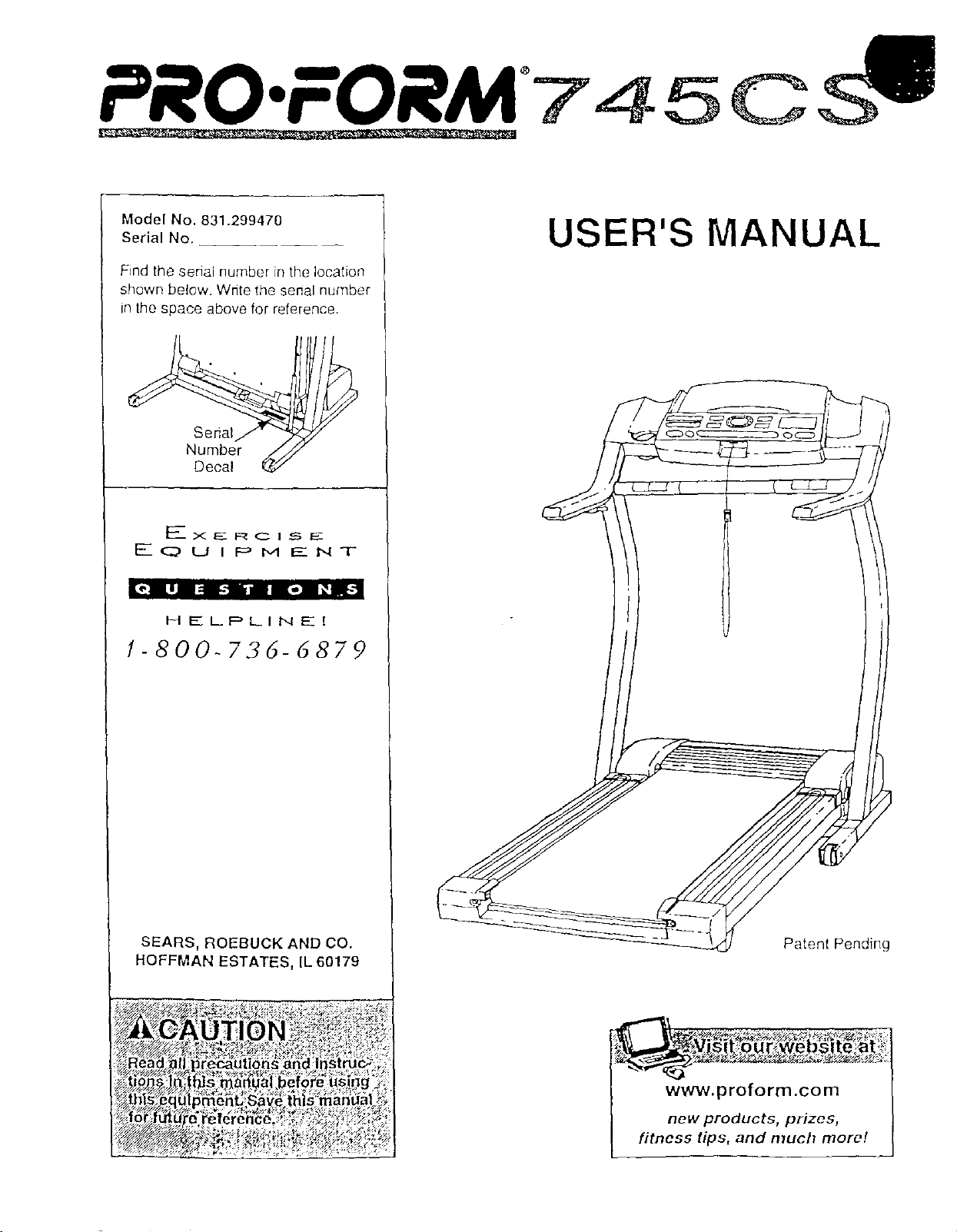
Model No. 831.299470
Serial No.
Find the serial number in the location
shown below. Write the senal number
in the space above for reference.
Serial
Number
Decal
F____x E_ F:_ C I _ EE
EQUIPMENT
[_"l LlJ I= Llllll-] l_(il_
HELPLINE[
1-800-736-6879
SEARS, ROEBUCK AND CO.
HOFFMAN ESTATES, IL 60179
_,_,_..g_ _
_egautlons and_nstru_.4
_s _a_al befo[e us gg _
,menDSave thls man_al__;
USER'S MANUAL
Patent Pending
www.proform.com
new products, prizes,
fitness tips, and much more!
PRO'FORM'745CS
TABLE OF CONTENTS
IMPORTANT PRECAUTIONS ................................................................. 3
BEFORE YOU BEGIN ....................................................................... 5
ASSEMBLY ............................................................................... 6
OPERATION AND ADJUSTMENT ............................................................. 9
HOW TO FOLD AND MOVE THE TREADMILL .................................................. 20
TROUBLE-SHOOTING ..................................................................... 22
CONDITIONING GUIDELINES ............................................................... 24
PART LIST ............................................................................... 27
ORDERING REPLACEMENT PARTS .................................................. Back Cover
FULL 90-DAY WARRANTY ........................................................... Back Cover
Note: An EXPLODED DRAWING is attached in the center of this manual.
2

IMPORTANT PRECAUTIONS
;ons, read ihe
see
66-7278 and
3
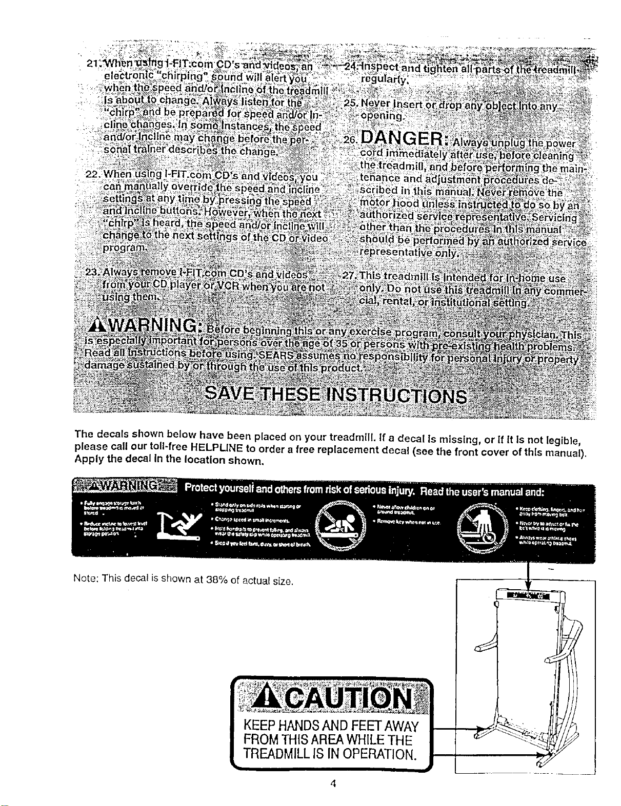
The decals shown below have been placed on your treadmill. If a decal Is missing, or if It Is not legible,
please call our toll-free HELPLINE to order a free replacement decal (see the front cover of this manual).
Apply the decal in the location shown.
Note: This decal is shown at 38% of actual size.
4
BEFORE YOU BEGIN
Thank you for selecting the revolutionary PROFORM e
745CS treadmill. The 745CS treadmill combines ad-
vanced technology with innovative design to help you
get the most from your exercise program in the conve-
nience and pdvacy of your home. And when you're not
exercising, the unique 745CS can be folded up, requir-
ing less than half the floor space of other treadmills.
For your benefit, read this manual carefully before
using the treadmill. Ifyou have additional questions,
please call our toll-free HELPLINE at 1-800-736-6879,
Monday through Saturday, 7 a.m. until 7 p.m. Central
Time (excluding holidays). To help us assist you,
please note the product model number and serial num-
ber before calling. The model number of the treadmill
is 831.299470. The serial number can be found on a
decal attached to the treadmill (see the front cover of
this manual for the location).
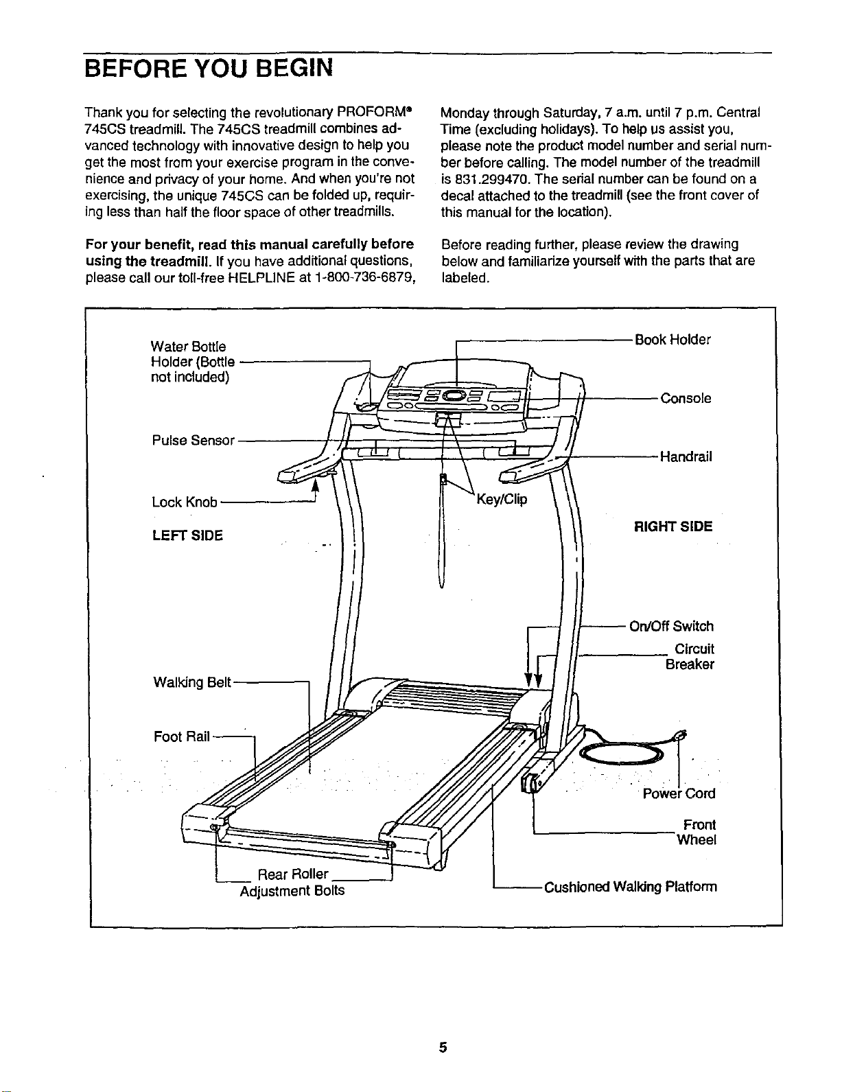
Before reading further, please review the drawing
below and familiadze yourself with the parts that are
labeled.
Water Bottle
Holder (Bottle
not included)
Book Holder
Console
Pulse Sensor
Handrail
Lock Knob
LEFT SIDE
RIGHT SIDE
Walking Belt
Circuit
Breaker
Foot
Powe 3ord
Front
Wheel
Rear Roller
Adjustment Bolts
Cushioned Walldng Platform
-ASSEMBLY
Assembly requires two people. Set the treadmill in a cleared area and remove all packing matenals. Do not
dispose of the packing materials until assembly is completed. Assembly requires your own Phillips screw-
driver (]_=======, wire cutters _, and rubber mallet {_:z_:_.
Note: The underside of the treadmill walking belt is coated with high-performance lubricant. During shipping,a
small amount of lubricant may be transferred to the top of the walking belt or the shipping carton. This is a normal
condition and does not affect treadmill performance. If there is lubricant on top of the walking belt, simply wipe off
the lubricant with a soft cloth and a mild, non-abrasive cleaner.
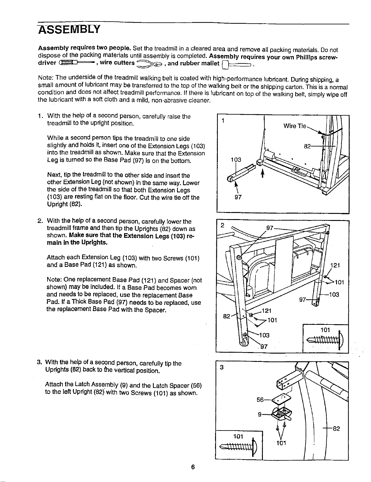
1. With the help of a second person, carefully raise the
treadmill to the upright position.
While a second person tips the treadmill to one side
slightly and holds it, insert one of the Extension Legs (103)
into the treadmill as shown. Make sure that the Extension
Leg is turned so the Base Pad (97) is on the bottom.
Next, tip the treadmill to the other side and insertthe
other Extension Leg (not shown) in the same way. Lower
the side of the treadmill so that both Extension Legs
(103) are resting fiat on the floor. Cut the wire tie off the
Upnght (82).
1
97
Wire Tie
82--
2. With the help of a second person, carefully lower the
treadmill frame and then tip the Uprights (82) down as
shown. Make sure that the Extension Legs (103) re-
main in the Uprights.
Attach each Extension Leg (103) with two Screws (101)
and a Base Pad (121) as shown.
Note: One replacement Base Pad (121) and Spacer (not
shown) may be included. If a Base Pad becomes worn
and needs to be replaced, use the replacement Base
Pad. If a Thick Base Pad (97) needs to be replaced, use
the replacement Base Pad with the Spacer.
3. With the help of a second person, carefully tip the
UPdghts (82) back to _e vertical position.
Attach the Latch Assembly (9) and the Latch Spacer (56)
to the left Upright (82) with two Screws (101) as shown.
,101
3
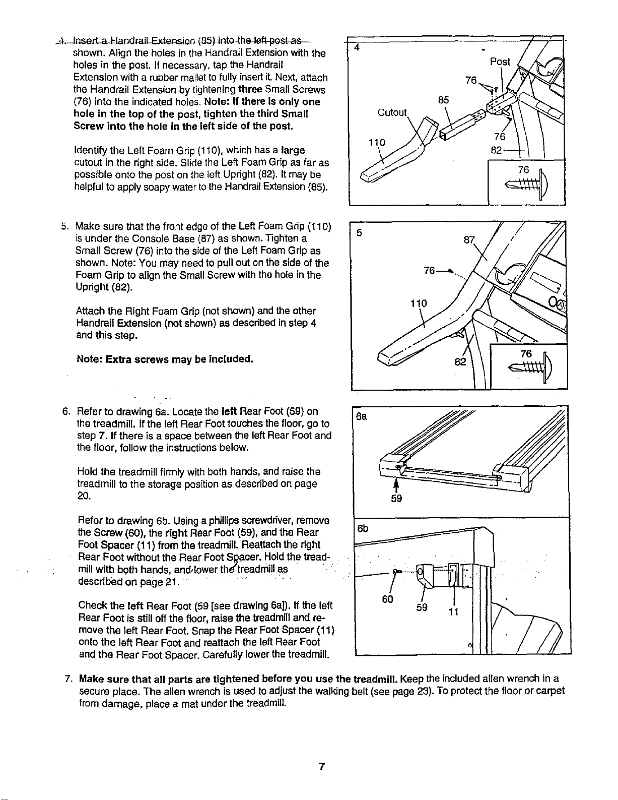
_4-JaserLaJ_andraiLExtensicn(85)Jnto_heJeft_oskas_
shown.AligntheholesintheHandrailExtensionwiththe
holesinthepost.Ifnecessary,taptheHandrail
Extensionwitharubbermallettofullyinsertit.Next,attach
theHandrailExtensionbytighteningthreeSmallScrews
(76)intotheindicatedholes.Note:IfthereIsonlyone
holeinthetopofthepost,tightenthethirdSmall
Serewintotheholeintheleftsideofthepest,
IdentifytheLeft Foam Gnp (110), which has a large
cutout in the right side. Slide the Left Foam Grip as far as
possible onto the post on the left Updght (82). It may be
helpful to apply soapy water to the Handrail Extension (85).
Cutout
\
110
85
Post
76._
5. Make sure that the front edge of the Left Foam Gdp (110)
is under the Console Base (87) as shown. Tighten a
Small Screw (76) into the side of the Left Foam Gdp as
shown. Note: You may need to pull out on the side of the
Foam Grip to align the Small Screw with the hole in the
Upright (82).
Attach the Right Foam Grip (net shown) and the other
Handrail Extension (not shown) as described in step 4
end this step.
Note: Extra screws may be included.
6. Refer te drawing 6a. Lecate the left Rear Foot (59) on
the treadmill, if the left Rear Foot touches the floor, go to
step 7. If there is a space between the left Rear Foot and
the floor, follow the instructions below.
Hold the treadmill firmly with both hands, and raise the
treadmill to the storage position as described on page
20.
Refer te drawing 6b. Using a phillips screwdriver,remove
the Screw (60), the right Rear Foot (59), and the Rear
Foot Spacer (11) from the treadmill. Reattach the right
Rear Foot without the Rear Foot Sl_aoer. Hold the tread-
mill witb both hands and, lower the'treadmill as
described on page 21.
Check the left Rear Foot (59 [see drawing 6a]). If the left
Rear Foot is still off the floor, raise the treadmill and re-
move the left Rear Foot. Snap the Rear Foot Spacer (11)
onto the left Rear Foot and reattach the left Rear Foot
and the Rear Foot Spacer. Carefully lower the treadmill.
6a
87
76---_..
59
7. Make sure that all parts are tightened before you use the treadmill. Keep the included allen wrench in a
secure place. The allen wrench is used to adjust the walking belt (see page 23). To protect the floor or carpet
from damage, place a mat under the treadmill.
7
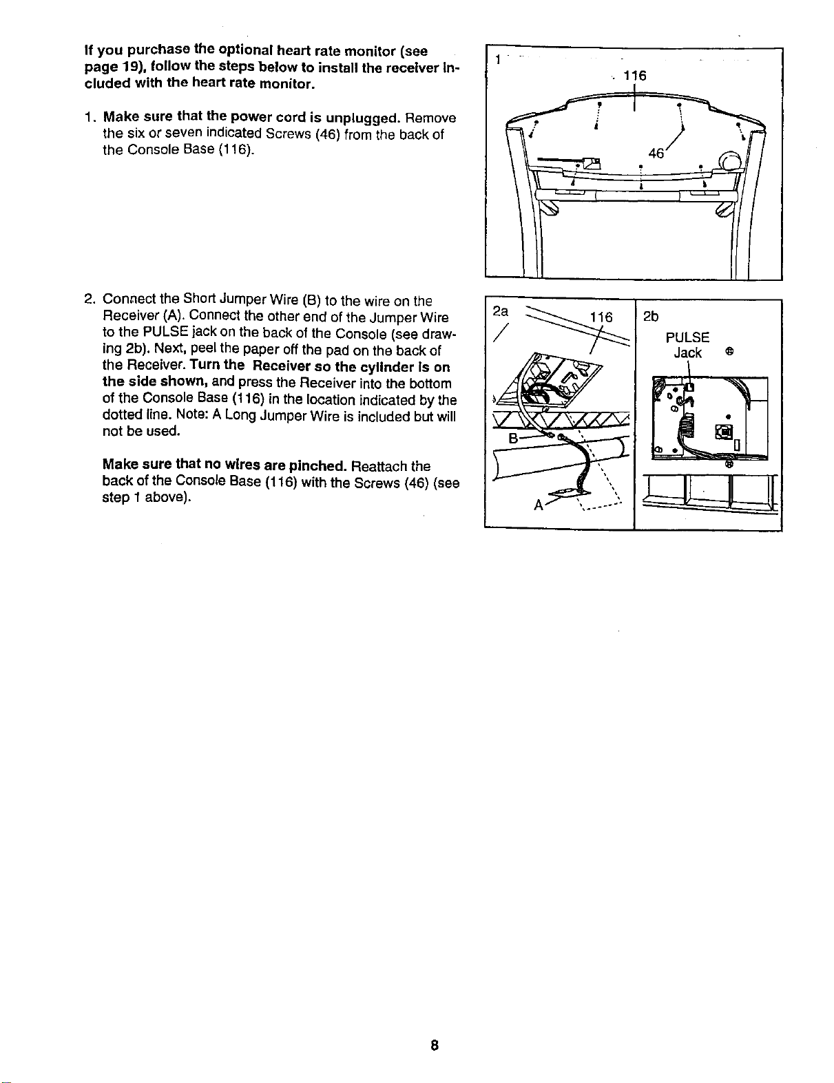
If you purchase the optional heart rate monitor (see
page 19), follow the steps below to install the receiver In-
cluded with the heart rate monitor.
1. Make sure that the power cord is unplugged. Remove
the six or seven indicated Screws (46) from the back of
the Console Base (116).
2. Connect the Short Jumper Wire (B) to the wire on the
Receiver (A). Connect the other end of the Jumper Wire
to the PULSE jack on the back of the Console (see draw-
ing 2b). Next, peel the paper off the pad on the back of
the Receiver. Turn the Receiver so the cylinder ls on
the side shown, and press the Receiver into the bottom
of the Console Base (116) in the location indicated by the
dotted line. Note: A Long Jumper Wire is included but will
not be used.
Make sure that no wires are pinched. Reattach the
back of the Console Base (116) with the Screws (46) (see
step 1 above).
1
.. 116
2a
/
2b
PULSE
Jack o
8
OPERATION AND ADJUSTMENT
THE PERFORMANT LUBE TM WALKING BELT
Your treadmill features a walking belt coated with
PERFORMANT LUBETM, a high-performance lubricant.
IMPORTANT: Never apply silicone spray or other
substances to the walking belt or the walking plat-
form. Such substances will deteriorate the walking
belt and cause excessive wear.
HOW TO PLUG IN THE POWER CORD
Your treadmill, like any other type of sophisticated
electronic equipment, can be seriously damaged by
sudden voltage changes in your home's power.
Voltage surges, spikes, and noise interference can
result from weather conditions or from other appliances
being turned on or off. To decrease the possibility of
your treadmill being damaged, always use a surge
suppressor with your treadmill (see drawing 1 at
the right).
To purchase a surge suppressor, see your local
SEARS or call toll-free 1-800-366-7278 and order
part number 146148. Use only a single-outlet surge
suppressor that is UL 1449 listedas a transient voltage
surge suppressor (TVSS). The surge suppressor must
have a UL suppressed voltage rating of 400 volts or
less and a minimum surge dissipation of 450 joules.
The surge suppressor must be electrically rated for
120 volts AC and 15 amps.
This product must be grounded. If it should malfunc-
tion or break down, grounding provides a path of least
resistance for electdc current to reduce the risk of elec-
tnc shock. This product is equipped with a cord having
an equipment-grounding conductor and a grounding
plug. Plug the power cord into a surge suppressor,
and plug the surge suppressor into an appropriate
ouUet that Is properly installed and grounded in
accordance with all local codes and ordinances.
Important: The treadmill is not compatible with
GFCl-equlpped outlets.
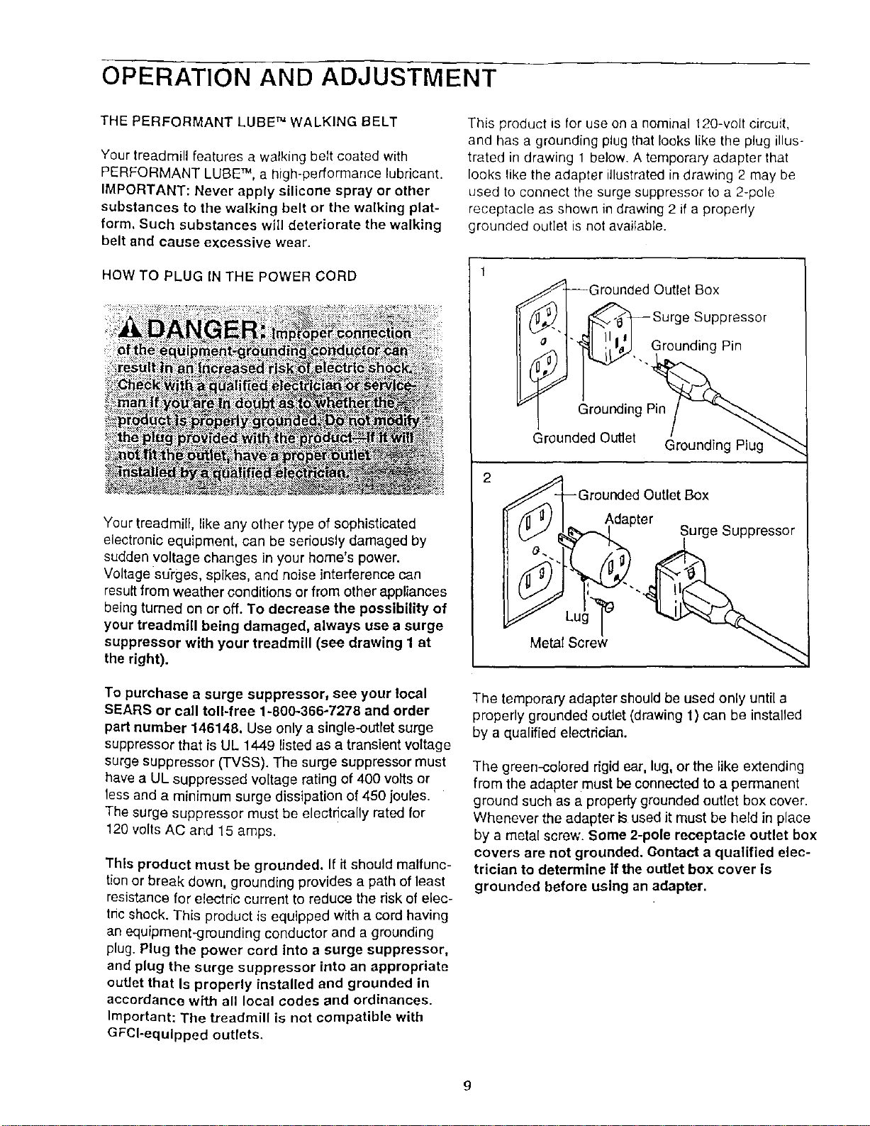
This product is for use on a nominal 120-volt circuit,
and has a grounding plug that looks like the plug illus-
trated in drawing 1 below. A temporary adapter that
looks like the adapter illustrated in drawing 2 may be
used to connect the surge suppressor to a 2-pole
receptacle as shown in drawing 2 if a properly
grounded outlet is not available.
2
irounded Outlet Box
Surge Suppressor
"_. Grounding Pin
Grounding Pin
Grounded Outlet
Grounding Plug
v]_-(_// _/. _ ._ge Suppressor
Metal Scra_w
The temporary adapter should be used only until a
properly grounded outlet (drawing 1) can be installed
by a qualified electrician.
The green-colored rigid ear, lug, orthe like extending
from the adapter must be connected to a permanent
ground such as a properly grounded outlet box cover.
Whenever the adapter is used it must be held in place
by a metal screw. Some 2-pole receptacle outlet box
covers are not grounded. Oontact a qualified elec-
trician to determine if the outlet box cover Is
grounded before using an adapter.
g
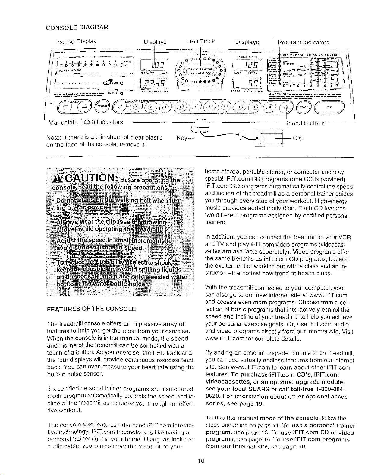
CONSOLE DIAGRAM
Program Indicators
Manual/iFIT.com Indicators
Note: If there is a thin sheet of clear plastic
on the face of the console, remove it.
FEATURES OF THE CONSOLE
The treadmill console offers an impressive array of
features to help you get the most from your exercise•
When the console is in the manual mode, the speed
and Incline of the treadmill can be controlled with a
touch of a button. As you exercise, the LED track and
the four displays will provide continuous exercise feed-
ba'ck. You can even measure your heart rate using the
built-In pulse sensor•
Six certified personal trainer programs are also offered.
Each program automatically controls the speed and ir_
cline of the treadmill as it guides you through an effec
tive workout.
] he console also feature_; advanced it-l l.com interac-
lwe technology. IFFF.com technology is like having a
pcrsonal trainer right in your home Using the included
/ltldio cable, you can r;ormt;ct the trea(hrli[I to your
home stereo, portable stereo, or computer and play
special iFIT.com CD programs (one CD is provided).
IFIT.cem CD programs automatically control the speed
and incline of the treadmill as a personal trainer guides
you through every step of your workout. High-energy
music provides added motivation. Each CD features
two different programs designed by certified personal
trainers•
In addition, you can connect the treadmill to your VCR
and TV and play iFIT.com video programs (videocas-
settes are available separately). Video programs offer
the same benefits as iFIT.com CD programs, but add
the excitement of working out with a class and an in-
structor-the hottest new trend at health clubs•
With the treadmill connected to your computer, you
can also go to our new internet site at www.iFIT.com
and access even more programs. Choose from a se-
lection of basic programs that interactively control the
speed and incline of your treadmill to help you achieve
your personal exercise goals. Or, use iFIT.com audio
and video programs directly from our interne2 site. Visit
www.iFIT.com for complete details.
By adding an optional upgrade module to the treadmill,
you can use virtua!ly endless features from our intemet
site. See www.IFlT.com to learn about other iFIT.com
features. To purchase IFlT.com CD's, IFIT.com
videocassettes, or an optional upgrade module,
see your local SEARS or call toll-free 1-800-884-
0620. For information about other optional acces-
sories, see page 19.
To use the manual mode of the console, follow tile
steps beginning on page tl To use a personal trainer
program, see page 13. To use iFIT.com CD or video
programs, see page 16 To use IFIT.com programs
from our internet site, see page 18
10
HOW TO TURN ON THE POWER
g Plug in the power cord (see HOW TO PLUG IN
THE POWER CORD on page 9).
B
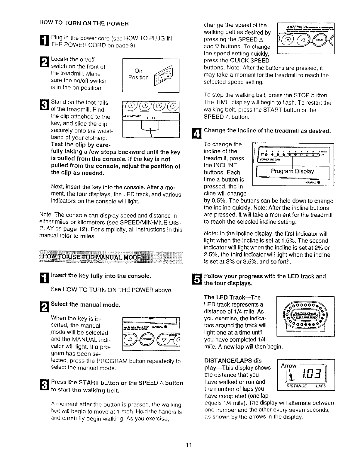
Locate the on/off
switch on the front of
the treadmill. Make
sure the on/off switch
is in the on position.
°.¢9
Position
Stand on the toot rails
of the treadmill. Find
the clip attached to the
key, and slide the clip
securely onto the waist-
band of your cfothing.
Test the clip by care-
fully taking a few steps backward until the key
is pulled from the console. If the key is not
pulled from the console, adjust the position of
the clip as needed.
Next, insert the key into the console. After a mo-
ment, the four displays, the LED track, and various
indicators on the console will light.
Note: The console can display speed and distance in
either miles or kilometers (see SPEED/MIN-MILE DIS-
PLAY on page 12). For simplicity, all instructions in this
manual refer to miles.
_ HOLY:;?_17_IIRaqI4 I=:I.._^_MI r^ _ t_t'_rtl_._:_,_'_ • o _,_.'_*,%-_,.,,;_-_"* .. ;.;.
n Insert the key fully into the console.
See HOW TO TURN ON THE POWER above.
B
Select the manual mode.
When the key is in-
serted, the manual
mode will be selected
and the MANUAL indi-
cator will light. If a pro-
gram has been se-
lected, press the PROGRAM button repeatedly to
select the manual mode.
_ Press the START button or the SPEED A button
to start the walking belt.
A moment after the button is pressed, the walking
be(t will begin to move at 1 mph. Hold the handrails
and carefu(Iy begin walking. As you exercise,
change the speed of the
walking belt as desired by
pressing the SPEED A
and £' buttons. To change
the speed setting quickly,
press the QUICK SPEED
buttons. Note: After the buttons are pressed, it
may take a moment for the treadmill to reach the
selected speed setting.
To stop the walking belt, press the STOP button.
The TIME display will begin to flash. To restart the
walking belt, press the START button or the
SPEED _. button.
B Change the incline of the treadmill as desired.
To change the
incline of the
treadmill, press
the INCLINE
buttons. Each
time a button is
pressed, the in-
cline will change
_O
by 0.5%. The buttons can be held down to change
the incline quickJy. Note: After the incline buttons
are pressed, it will take a moment for the treadmill
to reach the selected incline setting.
Note: In the inclinedisplay, the first indicator will
light when the incline is set at 1.5%. The second
indicator will light when the incline is set at 2% or
2.5%, the third indicator will light when _e incline
is set at 3% or 3.5%, and so forth.
H Follow your progress with the LED track and
the four displays.
The LED Track--The
LED track represents a
distance of 1/4 mile. As
you exercise, the indica-
tors around the track will
light one at a time until
you have completed 1/4
mile. A new lap will then begin.
DISTANCE/LAPS dis-
play--This display shows
the distance that you
have walked or run and
the number of laps you
have completed (one lap
equals 1/4 mile). The display will altemate between
one number and the other every seven seconds,
as shown by the arrows in the display
11
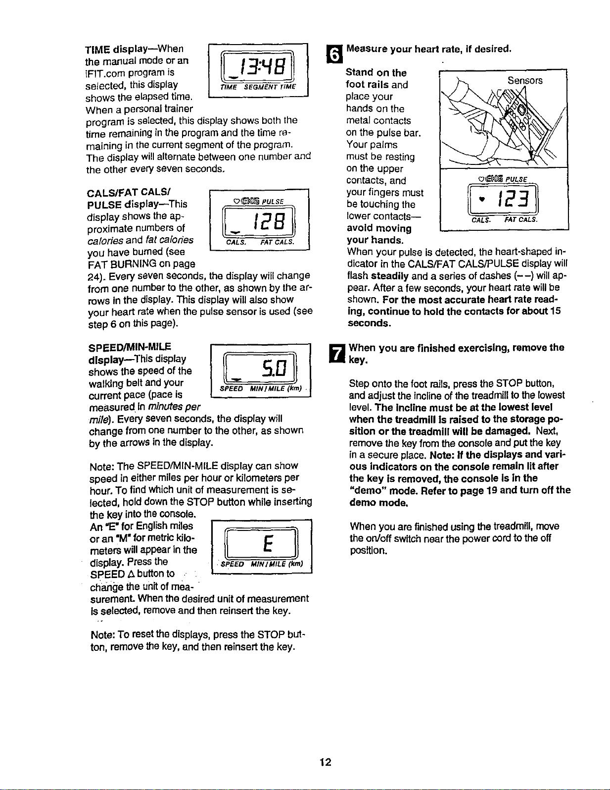
TIME display--When
the manual mode or an
iFIT.com program is
selected, this display
shows the elapsed time.
When a personal trainer
program is selected, this display shows both the
time remaining in the program and the time re-
maining in the current segment of the program.
The display will alternate between one number and
the other every seven seconds.
CALS/FAT CALS/
PULSE display--This
display shows the ap-
proximate numbers of
calories and fat calodes
you have burned (see
FAT BURNING on page
24). Every seven seconds, the display will change
from one number to the other, as shown by the ar-
rows in the display. This display will also show
your heart rate when the pulse sensor is used (see
step 6 on this page).
_(_ PULSE
/
ll-12 Jl
CALS, FAT CALS.
SPEED/MIN-MILE
dlsplaymThis display
shows the speed of the
walking belt and your
current pace (pace is
measured In minutes per
SPEED MIN/MILE (kin)
mile). Every seven seconds, the display will
change from one number to the other, as shown
by the arrows in the display.
Note: The SPEED,'MIN-MILE display can show
speed in either miles per hour or kilometers per
hour. To find which unit of measurement is se-
lected, hold down the STOP button while inserting
the key into the console.
An "E" for English miles
or an "M" for metric kilo-
meters will appear in the
display. Press the
SPEED A button to
cl_a_ge the unit of mea-
suremenL When the desired unit of measurement
Is selected, remove and then reinsert the key.
Note: To reset the displays, press the STOP but-
ton, remove the key, and then reinsert the key.
r_ Measure your heart rate, if desired.
Stand on the
foot rails and
place your
hands on the
metal contacts
on the pulse bar.
Your palms
must be resting
on the upper
contacts, and _ PULSE
your fingers must
be touching the " 123
lower contacts-- CALS. FATCALS.
avoid moving
your hands.
When your pulse is detected, the heart-shaped in-
dicator in the CALS/FAT CALS/PULSE display will
flash steadily and a sedes of dashes (--) will ap-
pear. After a few seconds, your heart rate will be
shown. For the most accurate heart rate read-
ing, continue to hold the contacts for about 15
seconds.
B When you are finished exercising, remove the
key.
Step onto the foot rails, press the STOP button,
and adjust the inclineof the treadmill to the lowest
level. The incline must be at the lowest level
when the treadmill Is raised to the storage po-
sition or the treadmill will be damaged, Next,
remove the key from the console and put the key
in a secure place. Note: If the displays and vari-
ous indicators on the console remain lit after
the key is removed, the console Is In the
"demo" mode, Refer to page 19 and turn off the
demo mode,
When you are finished using the treadmill, move
the on/off switch near the power cord to the off
position.
12
_1 Insert the key into the console.
See HOW TO TURN ON THE POWER on page
ft.
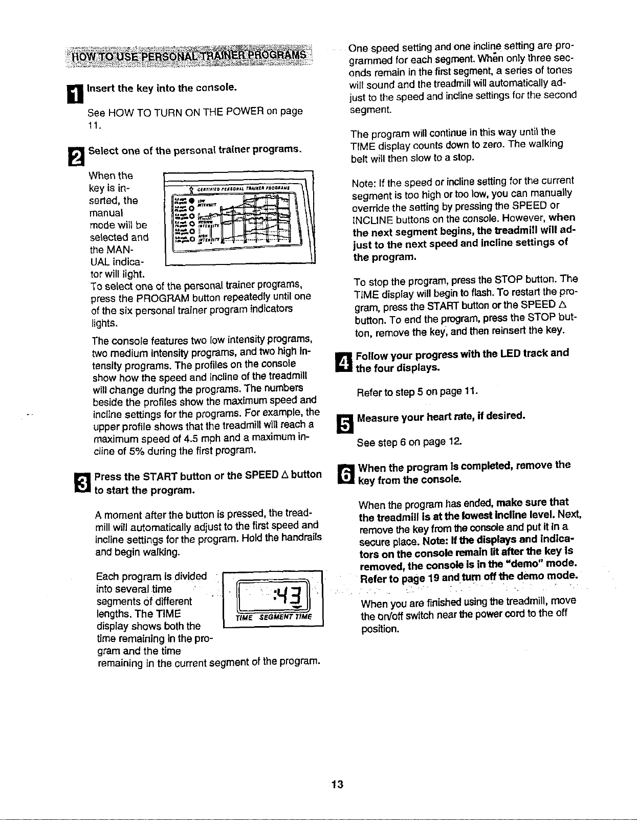
B Select one of the personal trainer programs.
When the
key is in-
serted, the
manuel
mode will be
selected and
the MAN-
UAL indica-
tor will light.
u,_O II
To select one of the personal trainer programs,
press the PROGRAM button repeatedly until one
of the six personal trainer program indicators
lights.
The console features two low intensity programs,
two medium intensity programs, and two high in-
tensity programs. The profiles on the Console
show how the speed and incline of the treadmill
willchange during the programs. The numbers
beside the profiles show the maximum speed and
incline settings for the programs. For example, the
upper profile shows that the treadmill will reach a
maximum speed of 4.5 mph and a maximum in-
cline of 5% during the first program.
One speed setting and one incline setting are pro-
grammed for each segment. When only three sec-
onds remain in the first segment, a series of tones
will sound and the treadmill will automatically ad-
just to the speed and incline settings for the second
segment.
The program willcontinue in this way until the
TtME display counts down to zero. The walking
belt will then slow to a stop.
Note: If the speed or inclinesetting for the current
segment is too high or too low, you can manually
override the setting by pressing the SPEED or
iNCLINE buttons on the console. However, when
the next segment begins, the treadmill will ad-
just to the next speed and incline settings of
the program.
To stop the program, press the STOP button. The
TIME display win begin to flash. To restart the pro-
gram, press the START button or the SPEED A
button. To end the program, press the STOP but-
ton, remove the key, and then reinsett the key.
B Follow your progress with the LED track and
the four displays.
Refer to step 5 on page 11.
B Measure your heart rate, if desired.
See step 6 on page 12.
[_1 Press the START button or the SPEED A button
to start the program.
A moment after the button is pressed, the tread-
mill will automatically adjust to the first speed and
incline settings for the program. Hold the handrails
and begin walking.
Each program {sdivided. :t
intoseveral time
segments of different
I
lengths.The TIME
display shows both the
time remaining in the pro-
gram and the time
r_ When the program Is completed, remove the
key from the console.
When the program has ended, make sure that
the treadmill Is at the lowest Incline level. Next,
remove the key from the console and put it in a
secure place. Note: ffthe displays and indica-
tors on the console remain lit after the key Is
removed, the console is in the "demo, mode.
When you are finishedusing the treadmill, move
rtM_' SEGMENTTIM_ the On/off switch near the power cord to the off
position.
remaining in the current segment of the program•
13
To use iFIT.com CD's, the treadmill must be con-
nected to your portable CD player, portable stereo.
home stereo, or computer with CD player. See pages
14 and 15 for connecting instructions. To use iFIT.corn
videocassettes, the treadmill must be connected to
your VCR. See page 16 for connecting instructions. To
use iFIT.com programs directly from our Internet
site, the treadmill must be connected to your home
computer. See page 15 for connecting instructions.
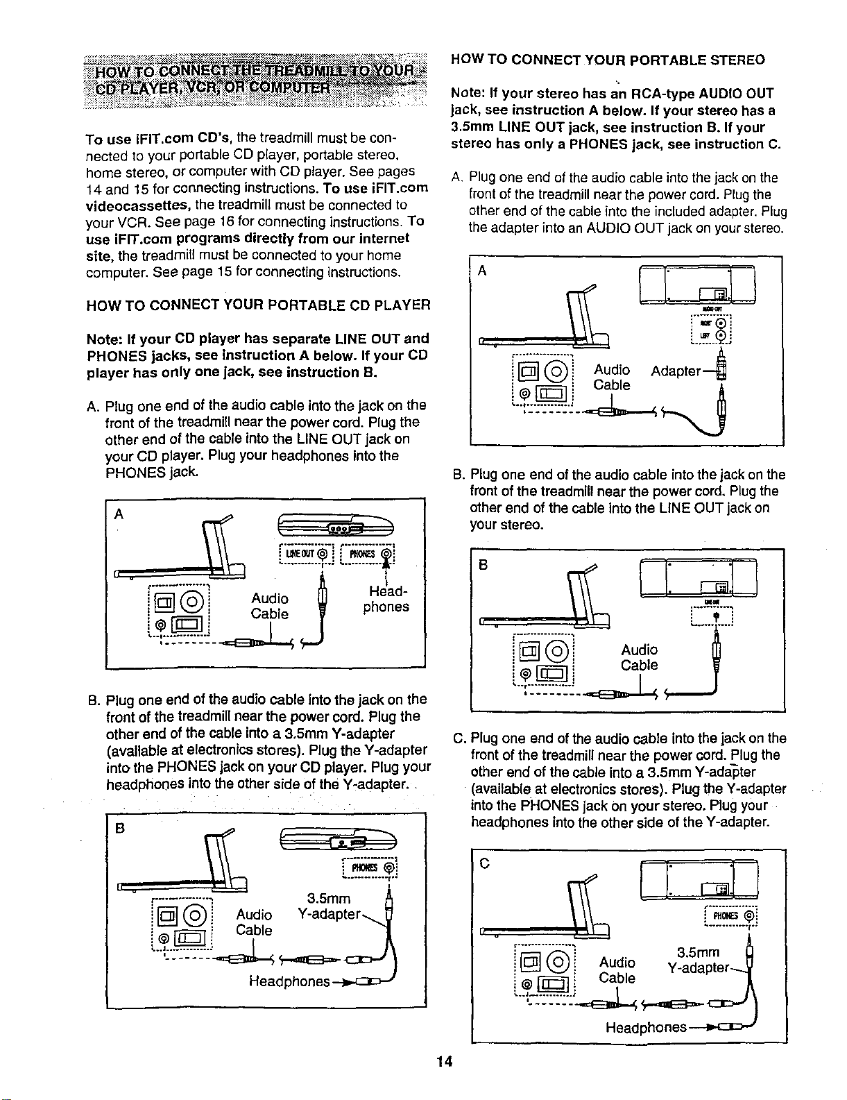
HOW TO cONNECT YOUR PORTABLE CD PLAYER
Note: If your CD player has separate LINE OUT and
PHONES jacks, see instruction A below. If your CD
player has only one jack, see instruction B.
A. Plug one end of the audio cable into the jack on the
front of the treadmill near the power cord. Plug the
other end of the cable into the LINE OUT jack on
your CD player. Plug your headphones into the
PHONES jack.
L........... i..: ' ............ .*
Audo j Head-
i_ Cable phones
B. Plug one end of the audio cable Into the jack on the
front of the treadmill near the power cord. Plug the
other end of the cable into a 3.Smm Y-adapter
(avaUable at electronics stores). Plug the Y-adapter
into the PHONES jack on your CD player. Plug your
headphones into the other side of the Y-adapter.
B
i
_-............ ; 3.5ram A
IFD--] (_i Audio Y-adapter-__
i - _} Cable "1
Headphones
HOW TO CONNECT YOUR PORTABLE STEREO
Note: If your stereo has an RCA-type AUDIO OUT
jack, see instruction A below. If your stereo has a
3.Smm LINE OUT jack, see instruction B. If your
stereo has only a PHONES jack, see instruction C.
A. Plug one end of the audio cable into the jack on the
front of the treadmill near the power cord. Plug the
other end of the cable into the included adapter. Plug
the adapter into an AUDIO OUT jack on your stereo.
A
I'F_" (_)'i Audio Adapter---_
' "@F'_ i Cable
B. Plug one end of the audio cable into the jack on the
front of the treadmill near the power cord, Plug the
other end of the cable intothe LINE OUT jack on
your stereo.
II .
"i
i F_] _"_ ! Audio
C. Plug one end ofthe audio cable into the jack on the
front of the treadmill near the power cord. Plug the
other end of the cable into a 3.5mm Y-adapter
(available at electronics storeS). Plug the Y-adapter
into the PHONES jack Onyour stereo. Plug your
headphones intothe other side of the Y-adapter.
C
I[ v
_-_"_"_ 3.Smm _]
i L_J (,._i Aud!o Y_adapter...._V
_ L;able _A
Headphones
14
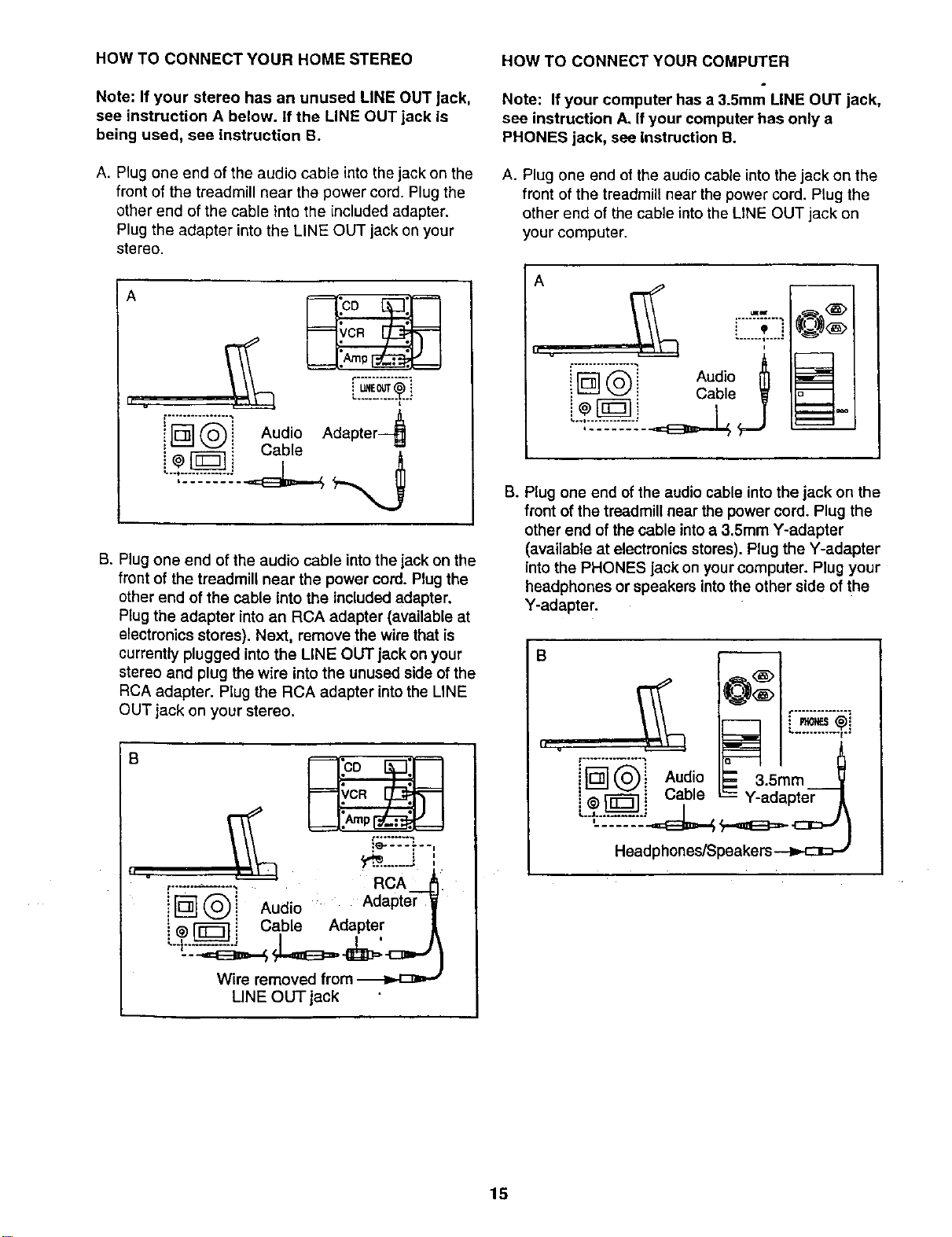
HOW TO CONNECT YOUR HOME STEREO
Note: If your stereo has an unused LINE OUT Jack,
see instruction A below. It the LINE OUT jack is
being used, see instruction B.
A. Plug one end of the audio cable into the jack on the
front of the treadmill near the power cord. Plug the
other end of the cable into the included adapter.
Plug the adapter into the LINE OUT jack on your
stereo.
A
.......... L.o.
t .................
![]® Aud,oAdapter
• Cable
B. Plug one end of the audio cable into the jack on the
front of the treadmill near the power cord. Plug the
other end of the cable into the included adapter.
Plug the adapter into an RCA adapter (available at
electronics stores). Next, remove the wire that is
currently plugged into the LINE OUT jack on your
stereo and plug the wire into the unused side of the
RCA adapter. Plug the RCA adapter into the LINE
OUT jack on your stereo.
S
tl .
,.........., R A.-
IN®j ud,o . Adapter
i @['_ i Cable Adapter
Wire removed from
LINE OUT jack
HOW TO CONNECT YOUR COMPUTER
Note: If your computer has a 3.5mm LINE OUT jack,
see instruction A. If your computer has only a
PHONES jack, see Instruction B.
A. Plug one end of the audio cable into the jack on the
front of the treadmill near the power cord. Plug the
other end of the cable into the LINE OUT jack on
your computer.
A
! 'P i
....... i .....
" Aud,o
_ _ Cable _
j
B. Plug one end of the audio cable into the jack on the
front of the treadmill near the power cord. Plug the
other end of the cable into a 3.5mm Y-adapter
(available at electronics stores). Plug the Y-adapter
into the PHONES jack on your computer. Plug your
headphones or speakers into the other side of the
Y-adapter.
B
i i Audo -- 35mm
]@_[ Q i Cable -- Y-adapter
15
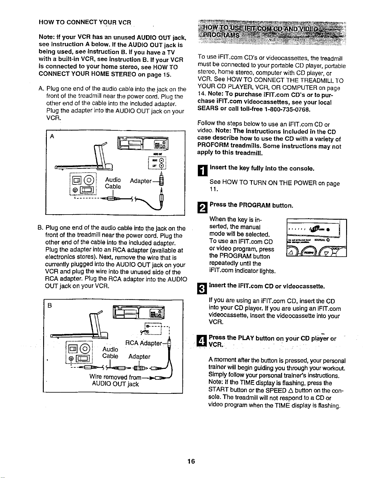
HOW TO CONNECT YOUR VCR
Note: if your VCR has an unused AUDIO OUT iack,
see instruction A below. If the AUDIO OUT jack is
being used, see instruction B. If you have a TV
with a built-in VCR, see instruction B. If your VCR
is connected to your home stereo, see HOW TO
CONNECT YOUR HOME STEREO on page 15.
A. Plug one end of the audio cable into the jack on the
front of the treadmill near the power cord. Plug the
other end of the cable into the included adapter.
Plug the adapter into the AUDIO OUT jack on your
VCR.
A
i
i _ _ Audio Adapter
@ i a_
B. Plug one end of the audio cable into the jack on the
front of the treadmill near the power cord. Plug the
other end of the cable intothe included adapter.
Plug the adapter into an RCA adapter (available at
electronics stores). Next, remove the wire that is
currently plugged into the AUDIO OUT jack on your
VCR and plug the wire into the unused side of the
RCA adapter. Plug the RCA adapter into the AUDIO
OUT jack on your VCR.
B
..%:.____.,:....
,
RcA
_";_L_,'-,;_" Adapter--_
ilD! Audio .....
!
! @ _ Cable Adapter |
Wire removed from.--._.c:_=,J
AUDIO OUT jack
........._,._ .,.,_ ,,............_ _ _ ..... , ....,.....
........... >_...... _!_ .... _ _"
To use iFIT.com CD's or v{deocassettes, the treadmill
must be connected to your portable CD player, portable
stereo, home stereo, computer with CD player, or
VCR. See HOW TO CONNECT THE TREADMILL TO
YOUR CD PLAYER, VCR, OR COMPUTER on page
14. Note: To purchase iPIT.com CD's or to pur-
chase iFIT.com videocassettes, see your local
SEARS or call toll-free 1-800-735-0768.
Follow the steps below to use an iFIT.com CD or
video. Note: The Instructions Included in the CD
case describe how to use the CD with a variety of
PROFORM treadmills. Some instructions may not
apply to this treadmitL
B Insert the key fully into the console,
See HOW TO TURN ON THE POWER on page
11.
B Press the PROGRAM button.
When the key is in-
serted, the manual
mode will be selected.
To use an iFIT.com CD
or video program, press
the PROGRAM button
repeatedly until the
iFIT.com indicator lights.
B Insert the iFIT.com CD or videocassette.
If you are using an iFIT.com CO, insert the CO
into your CD player. If you are using an iFIT.com
videocassette, insert the videocassette intoyour
VCR.
, _1 Press the PLAY button on your CO pla_r or
I hall VCR,
A moment after the button is pressed, yourpersonal
trainer will begin guiding you through yourworkout.
Simply follow your personal trainer's instructions.
Note: If the TIME display is flashing, press the
START button or the SPEED/k button on the con-
sole. The treadmill will not respond to a CD or
video program when the TIME display isflashing.
16
During the CD or video program, an electronic
"chirping" sound will alert you when the speed
and/or incline of the treadmill is about to change.
CAUTION: Always listen for the "chirp" and he
prepared for speed and/or Incline changes. In
some instances, the speed and/or incline may
change before the personal trainer describes
the change.
If the speed or incline settings are too high or too
low, you can manually override the settings at any
time by pressing the SPEED or INCLINE buttons
on the console. However, when the next "chirp"
is heard, the speed and/or incline will change
to the next settings of the CD or video program.
To stop the program at any time, press the STOP
button on the console. The TIME display will begin
to flash. To restart the program, press the START
button or the SPEED L_button. After a moment,
the walking belt will begin to move at 1 mph.
When the next "chirp" Is heard, the speed and
incline will change to the next settings of the
CD or video program. The program can also be
stopped by pressing the STOP buttonon your CD
player or VCR.
When the CD or video program iscompleted, the
walking belt willstop and the TIME display will
begin to flash. Note: To use another CD or video
program, press the STOP button or remove the
key and go to step 1 on page 16.
Note: If the speed or incline of the treadmill
does not change when a "chirp" is heard:
• make sure that the IFIT.com indicator is lit and
that the TIME display is not flashing. If the
TIME display Is flashing, press the START
button or the SPEED A button on the console
• adjust the volume of your CD player or VCR. If
the volume is too high or too low, the console
may not detect the program signals
• make sure that the audio cable is properly
connected, that it Is fully plugged in, and that
it is not wrapped around a power cord
• if you are using your portable CD player and
the CD skips, set the CD player on the floor or
another flat surface instead of on the console.
_"_ Follow your progress with the LED track and
the four displays.
See step 5 on page 11.
B Measure your heart rate, if desired.
See step 6 on page 12.
B When the IFIT.com CD or video program is
finished, remove the key.
See step 6 on page 13.
CAUTION: Always remove iFIT.com CD's and
videocassettes from your CD player or VCR
when you are finished using them.
17
Ournewinternetsiteatwww.iFtT.comallowsyouto
accessa largeselectionofprogramsthatinteractively
controlyourtreadmilltohelpyouachieveyourspecific
exercisegoals.Inaddition,youcanplayiFIT.com
audioandvideoprogramsdirectlyfromtheintemet.By
addinganoptionalupgrademoduletotheconsole,you
canusevirtuallyendlessfeaturesonourintemetsite.
Explorewww.iFIT.comfordetails.Topurchaseanup-
grademodule,seeyourlocalSEARSorcalltell-free1-
800-735-0765.
Touseprogramsfromourinternetsite,thetreadmiU
mustbeconnectedtoyourhomecomputer.SeeHOW
TOCONNECTYOURCOMPUTERonpage15.Inad-
dition,youmusthaveatleasta56Kmodemandan
accountwithaninternetserviceprovider.Alistofaddi-
tionalsystemandsoftwarerequirementswillbefound
onourinternetsite.
Follow the steps below to use a program from our
intemet site.
B thsert the key fully into the console.
See HOW TO TURN ON THE POWER on page 11.
E!
Press the PROGRAM button.
When the key is in-
serted, the manual
mode will be selected.
To use an iFIT.com CD
or video program, press
the PROGRAM button
repeatedly until the
iFIT.com indicator lights.
_lGo to your computer and start an internet
connection.
•1_1 Start your web browser, if necessary, end go to
iza
_ur jnternet site at www.iFIT.com.
_ Follow the desired links on our Internet site to
select a program.
Reed and foitow the on-line instructions for using a
program.
r_ Follow the on-line Instructions to start the
program.
When you start the program, an on-screen count-
down will begin.
B Return to the treadmill and stand on the foot
rails. Find the clip attached to the keyand slide
the key onto the waistband of your clothing.
When the on-screen countdown ends, the program
will begin and the walking belt will begin to move.
Hold the handrails, step onto the walking belt, and
begin walking.
During the program, an electronic =chirping" sound
willalert you when the speed and/or incline of the
treadmill is about to change. CAUTION: Alwa_/s
listen for the "chirp" and be prepared for speed
and/or incline changes.
If the speed or incline settings are too high or too
low, you can manually override the settings at any
time by pressing the SPEED or INCLINE buttons
on the console. However, when the next "chirp"
Is heard, the speed and/or incline will change
to the next settings of the program.
To stop the program at any time, press the STOP
button on the console. The TIME display will begin
to flash. To restart the program, press the START
button or the SPEED A. button. After a moment,
the walking belt will begin to move at 1 mph.
When the next "chirp" Is heard, the speed and
Incline will change to the next settings of the
program.
When the program is completed, the walldngbelt
will stop and the TIME display will begin to flash.
Note: To use another program, press the STOP
button and go to step 5 on this page.
Note: If the speed or incline of the treadmill
does not change when a "chirp" is heard, make
sure that the IFIT.com Indicator is lit and that
the TIME display is not flashing. In addition,
make sure that the audio cable is properly con-
nected, that it Is fully plugged In, end that it Is
not wrapped around e power cord.
_J FoUow your progress with the LED track and
the four displays.
See step 5 on page 11.
J_ Measure your heart rate, if desired.
See step 6 on page 12.
W When the program is finished, remove the
key.
See step 6 on page 13.
18
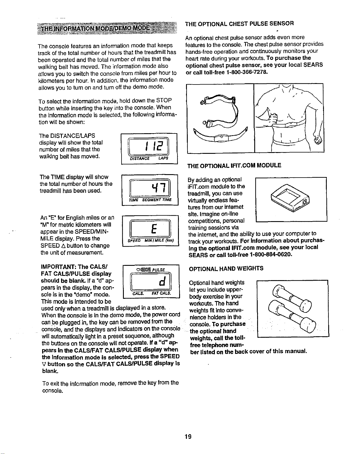
THE OPTIONAL CHEST PULSE SENSOR
An optional chest pulse sensor adds even more
features to the console. The chest pulse sensor provides
hands-free operation and continuously monitors your
heart rate during your workouts. To purchase the
optional chest pulse sensor, see your local SEARS
or call toll-free 1-800-366-7278.
The console features an information mode that keeps
track of the total number of hours that the treadmill has
been operated and the total number of miles that the
walking belt has moved. The information mode also
allows you to switch the console from miles per hour to
kilometers per hour. In addition, the information mode
To select the information mode, hold down the STOP
button while inserting the key into the console. When
the information mode is selected, the following informa-
tionwill be shown:
display will show the total
number of miles that the I 12
walking belt has moved. DISTANCE LAPS
The TiME display willshow
the total number of hours the
treadmill has been used.
/ ElI
SPEED MIN I MILE (krn)
An =E"for English miles or an
"M" for metdc kilometers will
appear in the SPEED/MIN-
MILE display. Press the
SPEED .,xbutton to change
the unit of measurement.
THE OPTIONAL IFIT.COM MODULE
By adding an optional
iFIT.com module to the
treadmill, you can use
virtuallyendless lea-
tures from our intemet
site. Imagine on-line
competitions, personal
training sessions via
the intemet, and the ability to use your computer to
track your workouts. For information about purchas-
Ing the optional IFIT.com module, see your Iooal
SEARS or call toll-free 1-800-884-0620.
IMPORTANT: The CALS/
FAT CALS/PULSE display
should be blank. If a "d"ap-
pears in the display, the con-
sole is in the "demo"mode.
This mode is Intended to be
o_ PULSE
(I
CALS. FAr CALS,
used only when a treadmill is displayed in a store.
When the Consoleis in the demo mode, the power cord
can be plugged in the key can be removed from the
console, and the •displaysand Indicators Onthe console
will automatically lightin a preset sequence, although
the buttons on the console will notoperate. If a "d" ap-
pears In the CALS/FAT CALS/PULSE display when
the Information mode is selected, press the SPEED
V button so the CALS/FAT CALS/PULSE display Is
blank.
OPTIONAL HAND WEIGHTS
Optional hand weights
let you include upper-
body exercise in your
workouts.The hand
weightsFitintoconve-
nienceholders in the
console. To purchase
the optional hand :
weights, call the toll-
free telephone num-
ber listed on the back cover of this manual.
To exit the information mode, remove the key from the
console.
19
HOW TO FOLD AND MOVE THE TREADMILL
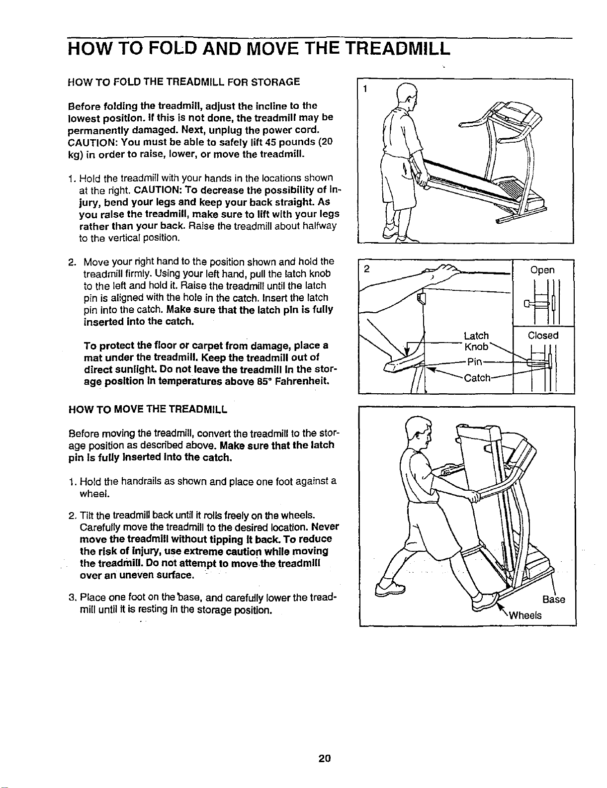
HOW TO FOLD THE TREADMILL FOR STORAGE
Before folding the treadmill, adjust the incline to the
lowest position. If this is not done, the treadmill may be
permanently damaged. Next, unplug the power cord.
CAUTION: You must be able to safely lift 45 pounds (20
kg) in order to raise, lower, or move the treadmill.
1. Hold the treadmill with your hands in the locations shown
at the right. CAUTION: To decrease the possibility of In-
jury, bend your legs end keep your back straight. As
you raise the treadmill, make sure to lift with your legs
rather than your back. Raise the treadmill about halfway
to the vertical position.
2. Move your right hand to the position shown and hold the
treadmill firmly. Using your left hand, pull the latch knob
to the left and hold it. Raise the treadmill until the latch
pin is aligned with the hole in the catch. Insert the latch
pin into the catch. Make sure that the latch pln is fully
inserted into the catch.
To protect the floor or carpet from damage, place a
mat under the treadmill. Keep the treadmill out of
direct sunlight. Do not leave the treadmill In the stor-
age position In temperatures above 85 ° Fahrenheit.
HOW TO MOVE THE TREADMILL
Before moving the treadmill, convert the treadmill to the stor-
age position as described above. Make sure that the latch
pin Is fully Inserted Into the catch.
1. Hold the handrails as shown and place one foot against a
wheel.
2. Tiff the treadmill back until it roils freely on the wheels.
Carefully move the treadmill to the desired location. Never
move the treadmill without tipping It back. To reduce
the risk of injury, use extreme cautio n while moving
the treadmill. Do not attempt to move the treadmill
over an uneven surface.
3. Place one foot on the 'base, and carefully lower the tread-
mill until it is resting in the storage position.
Latch
-- Knob_
._-"_ ._-------- Pin _
Catch---'"-
Open
Closed
_/heels
20
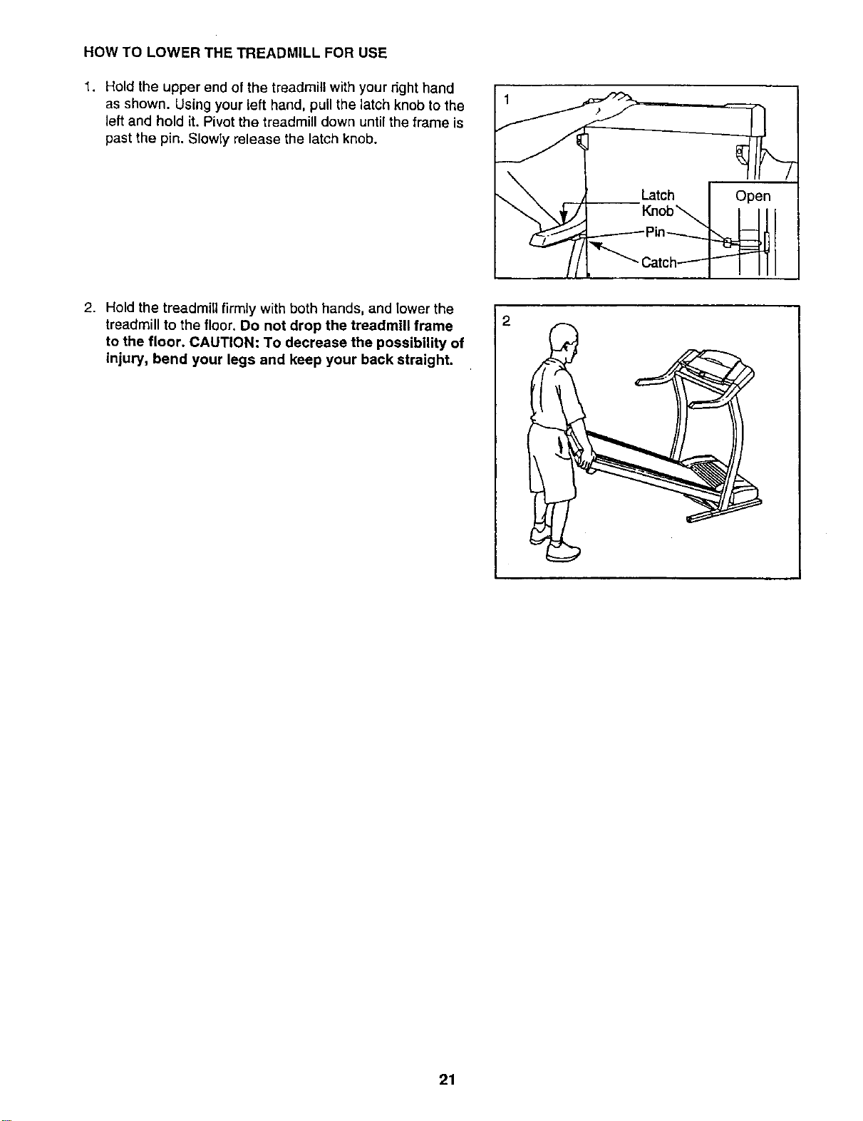
HOW TO LOWER THE TREADMILL FOR USE
1. Hold the upper end of the treadmill with your right hand
as shown. Using your left hand, pull the latch knob to the
left and hold it. Pivot the treadmill down until the frame is
past the pin. Slowly release the latch knob.
2. Hold the treadmill firmly with both hands, and lower the
treadmill to the floor. Do not drop the treadmill frame
to the floor. CAUTION: To decrease the possibility of
injury, bend your legs and keep your back straight.
21
t"ROU BI:E=SHOOTING
Most treadmill problems can be solved by following the simple steps below. Find the symptom that
applies, and follow the steps listed. If further assistance Is needed, call our toll-free HELPLINE at
1-800-736-6879, Monday through Saturday, 7 a.m. until 7 p.m. Central Time (excluding holidays).
PROBLEM: The power does not turn on
SOLUTION: a. Make sure that the power cord is plugged into a surge suppressor, and that the surge suppressor
is plugged into a properly grounded outlet (see page 9). Use only a single-outlet surge suppressor
that is UL 1449 listed as a transient voltage surge suppressor (TVSS). The surge suppressor
must have a UL suppressed voltage rating of 400 volts or less and a minimum surge dissipation
of 450 joules. The surge suppressor must be electrically rated for 120 volts AC and 15 amps.
Important: The treadmill is not compatible with GFCl-equipped outlets.
b. After the power cord has been plugged in, make sure that the key is fully inserted into the console.
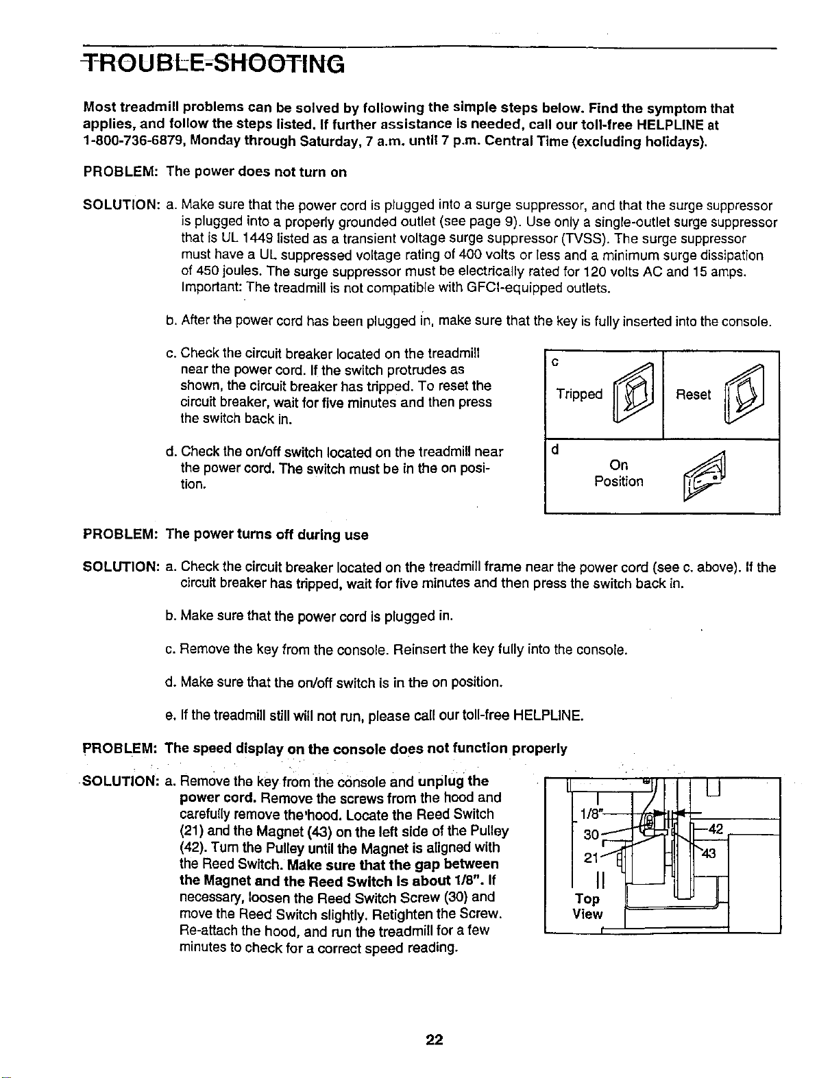
c. Check the circuit breaker located on the treadmill
near the power cord. If the switch protrudes as
shown, the circuit breaker has tdpped. To reset the
circuit breaker, wait for five minutes and then press
the switch back in.
d. Check the on/off switch located on the treadmill near
the power cord. The switch must be in the on posi-
tion.
c
Tripped
d
Reset
onj
Position
PROBLEM: The power turns off during use
SOLUTION: a. Check the circuit breaker located on the treadmill frame near the power cord (see c. above). If the
circuit breaker has tdpped, wait for five minutes and then press the switch back in.
b. Make sure that the power cord is plugged in.
c. Remove the key from the console. Reinsert the key fully into the console.
d. Make sure that the on/off switch is in the on position.
e. If the treadmill still will not run, please call our toll-free HELPLINE.
PROBLEM: The speed display on the console does not function properly
SOLUTION: a. Remove the key from the console and unplug the
power cord. Remove the screws from the hood and
carefully remove the'hood. Locate the Reed Switch
(21) and the Magnet (43) on the left side of the Pulley
(42). Turn the Pulley until the Magnet is aligned with
the Reed Switch. Make sure that the gap between
the Magnet and the Reed Switch Is about 118". If
necessary, loosen the Reed Switch Screw (30) and
move the Reed Switch slightly. Ratighten the Screw.
Re-attach the hood, and run the treadmill for a few
minutes to check for a correct speed reading.
Top
View
22
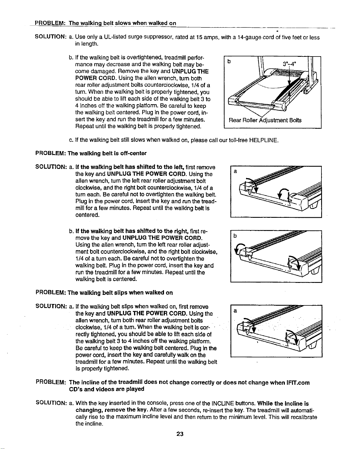
PROBLEM: The walking_belt slows when walked on
SOLUTION: a. Use only a UL-listed surge suppressor, rated at 15 amps, with a 14-gauge cord of five feet or less
in length.
b. If the walking belt is overtightened, treadmill perfor-
mance may decrease and the walking belt may be-
come damaged. Remove the key and UNPLUG THE
POWER CORD. Using the allen wrench, turn both
rear roller adjustment bolts counterclockwise, 1/4 of a
turn. When the walking belt is properly tightened, you
should be able to lift each side of the walking belt 3 to
4 inches off the walking platform. Be careful to keep
the walking belt centered. Plug in the power cord, in-
sert the key and run the treadmill for a few minutes.
Repeat until the walking belt is properly tightened.
Rear Roller Adjustment Bolts
c. If the walking belt still slows when walked on, please call our toll-free HELPLINE.
PROBLEM: The walking belt is off-center
SOLUTION: a. If the walking belt has shifted to the left, first remove
the key and UNPLUG THE POWER CORD. Using the
allen wrench, turnthe left rear roller adjustment bolt
clockwise, and the right boltcounterclockwise, 1/4 of a
turn each. Be careful not to overtighten the walking belt.
Plug in the power cord, Insert the key and run the tread-
millfor a few minutes. Repeat until the walking belt is
centered.
b. If the walking belt has shifted to the right, first re-
move the key and UNPLUG THE POWER CORD.
Using the allen wrench, tum the left rear rolleradjust-
ment bolt counterclockwise, and the right bolt clockwise
1/4 ofa turn each. Be careful not to overtighten the
walking belt. Plug in the power cord, insert the key and
run the treadmill for a few minutes. Repeat untilthe
walking belt iscentered.
b
PROBLEM: The walking belt slips when walked on
SOLUTION: a. if the walking belt slips when walked on, first remove
the key and UNPLUG THE POWER CORD. Using the
allen wrench, turn both rear rolleradjustment bolts
clockwise, 1/4 ofa turn. When the walking belt is cor-
rectly tightened, you should be able to lift each side of
the walking belt 3 to 4 inches offthe walking platform.
Be careful to keep the walking belt centered. Plugin the
power cord, insertthe key and carefully walk on the
treadmill for a few minutes. Repeat until the walking belt
is propedy tightened.
PROBLEM: The incline of the treadmill does not change correctly or does not change when IFn'.com
CD's and videos are played
SOLUTION: a. With the key inserted in the console, press one ofthe INCLINE buttons. While the Incline is
changing, remove the key. After a few seconds, re-insert the key.The treadmill will automati-
cally rise to the maximum incline level and then returnto the minimum revel. This will recalibrate
the incline.
23
CONDITIONING GUIDELINES
!i!ii_ii!i!i
The following guidelines will help you to plan your ex-
ercise program. Remember--these are general guide-
lines only. For more detailed exercise information, ob-
tain a reputable book or consult your physician.
EXERCISE INTENSITY
Whether your goal is to burn fat or to strengthen your
cardiovascular system, the key to achieving the
desired results is to exercise with the proper intensity.
The proper intensity level can be found by using your
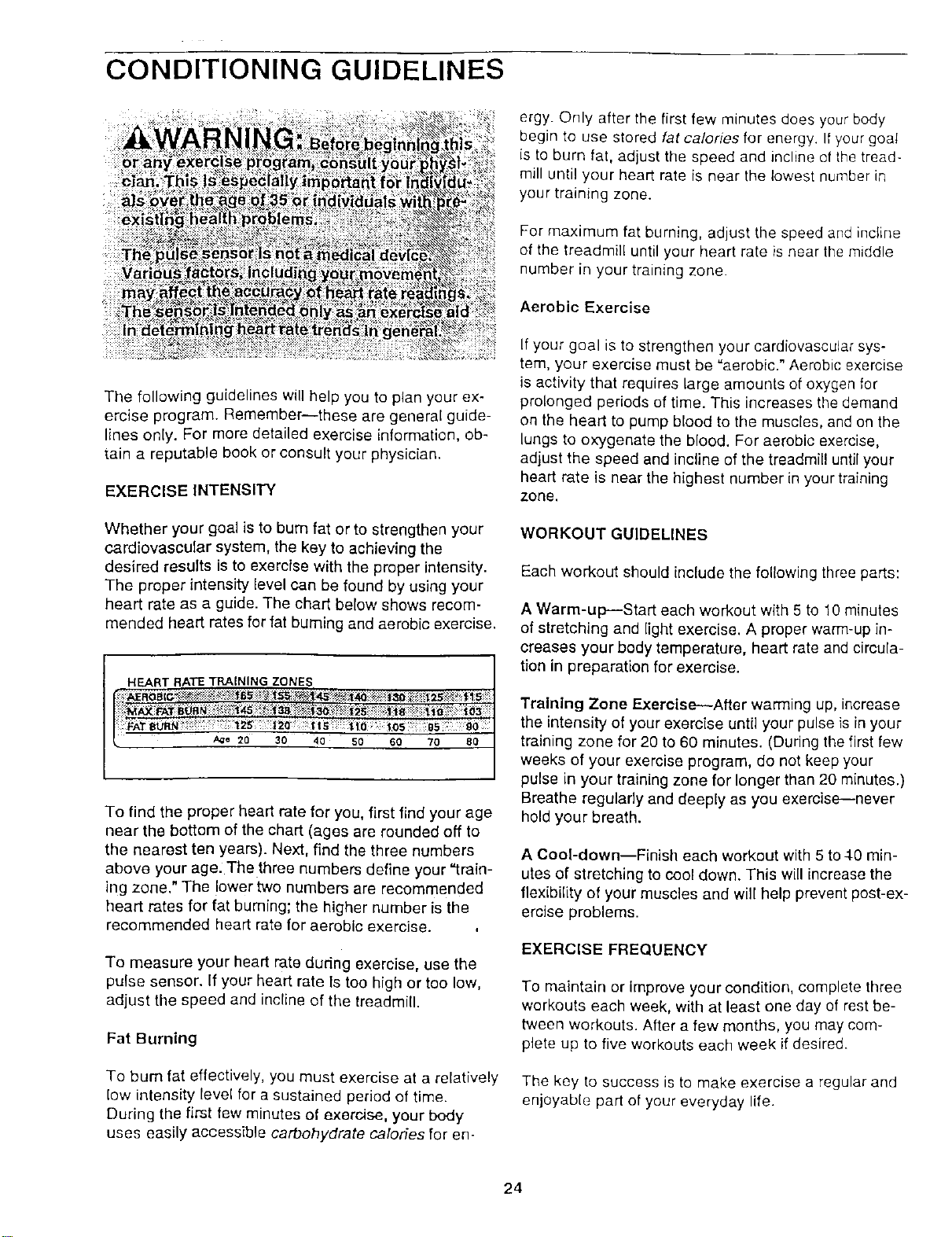
heart rate as a guide. The chart below shows recom-
mended heart rates for fat burning and aerobic exercise.
HEART RATE TRAINING ZONES
A_e 20 30 40 50 60 70 80
To find the proper heart rate for you, first find your age
near the bottom of the chart (ages are rounded off to
the nearest ten years). Next, find the three numbers
above your age. The three numbers define your "train-
ing zone." The lower two numbers are recommended
heart rates for fat buming; the higher number is the
recommended heart rate for aerobic exercise.
To measure your heart rate during exercise, use the
pulse sensor. If your heart rate Is too high or too low,
adjust the speed and incline of the treadmill.
Fat Burning
To bum fat effectively, you must exercise at a relatively
low intensity level for a sustained period of time.
During the first few minutes of exercise, your body
uses easily accessible carbohydrate calories for en-
ergy. Only after the first few minutes does your body
begin to use stored fat calories for energy. If your goal
is to burn fat, adjust the speed and incline of the tread-
mill until your heart rate is near the lowest number in
your training zone.
For maximum fat burning, adjust the speed and incline
of the treadmill until your heart rate is near the middle
number in your training zone.
Aerobic Exercise
If your goal is to strengthen your cardiovascular sys-
tem, your exercise must be "aerobic." Aerobic exercise
is activity that requires large amounts of oxygen for
prolonged periods of time. This increases the demand
on the heart to pump blood to the muscles, and on the
lungs to oxygenate the blood. For aerobic exercise,
adjust the speed and incline of the treadmill until your
heart rate is near the highest number in your training
zone.
WORKOUT GUIDELINES
Each workout should include the following three parts:
A Warm-up--Start each workout with 5 to 10 minutes
of stretching and light exercise. A proper warm-up in-
creases your body temperature, heart rate and circula-
tion in preparation for exercise.
Training Zone Exercise--After warming up, increase
the intensity of your exercise until your pulse is in your
training zone for 20 to 60 minutes. (During the first few
weeks of your exercise program, do not keep your
pulse in your training zone for longer than 20 minutes.)
Breathe regularly and deeply as you exercise---never
hold your breath.
A Cool-down--Finish each workout with 5 to4O min-
utes of stretching to cool down. This will increase the
flexibility of your muscles and will help prevent post-ex-
ercise problems.
EXERCISE FREQUENCY
To maintain or Improve your condition, complete three
workouts each week, with at least one day of rest be-
tween workouts. After a few months, you may com-
plete up to five workouts each week if desired.
The key to success is to make exercise a regular and
enjoyable part of your everyday life.
24
SUGGESTED STRETCHES
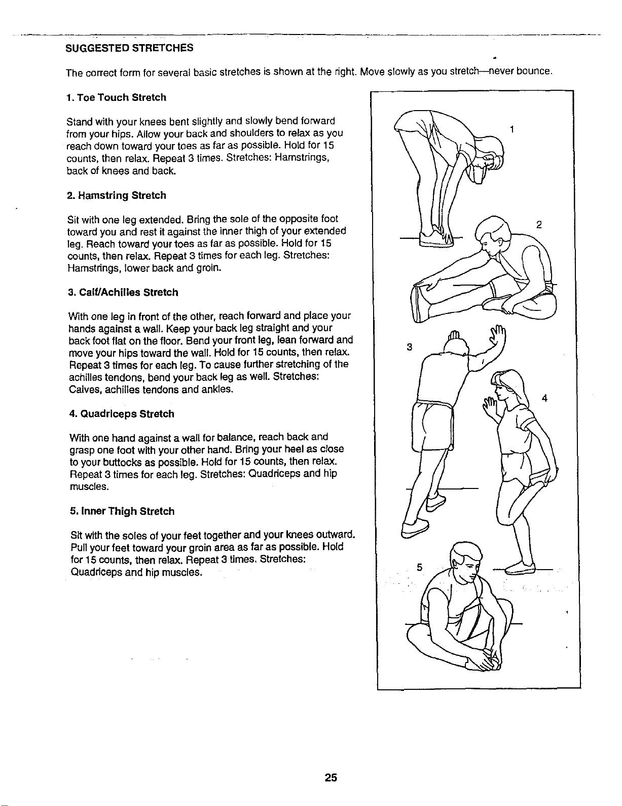
The correct form for several basic stretches is shown at the right. Move slowly as you stretch--never bounce.
1. Toe Touch Stretch
Stand with your knees bent slightly and slowly bend forward
from your hips. Allow your back and shoulders to relax as you
reach down toward your toes as far as possible. Hold for 15
counts, then relax. Repeat 3 times. Stretches: Hamstrings,
back of knees and back.
2. Hamstring Stretch
Sit with one leg extended. Bring the sole of the opposite foot
toward you and rest it against the inner thigh of your extended
leg. Reach toward your toes as far as possible. Hold for 15
counts, then relax. Repeat 3 times for each leg. Stretches:
Hamstrings, lower back and groin.
3. Calf/Achilles Stretch
With one leg in front of the other, reach forward and place your
hands against a wall. Keep your back leg straight and your
back foot flat on the floor. Bend your front leg, lean forward and
move your hips toward the wall. Hold for 15 counts, then relax.
Repeat 3 times for each leg. To cause further stretching of the
achilles tendons, bend your back leg as well. Stretches:
Calves, achilles tendons and ankles.
4. Quadrlceps Stretch
With one hand against a wall for balance, reach back and
grasp one foot with your other hand. Bdng your heel as close
to your buttocks as possible. Hold for 15 counts, then relax.
Repeat 3 times for each leg. Stretches: Quadriceps and hip
muscles.
5, Inner Thigh Stretch
Sit with the soles of your feet together and your knees outward.
Pull your feet toward your groin area as far as possible. Hold
for 15 counts, then relax. Repeat 3 times. Stretches:
Quaddceps and hip muscles.
3
2
4
25

NOTES
26
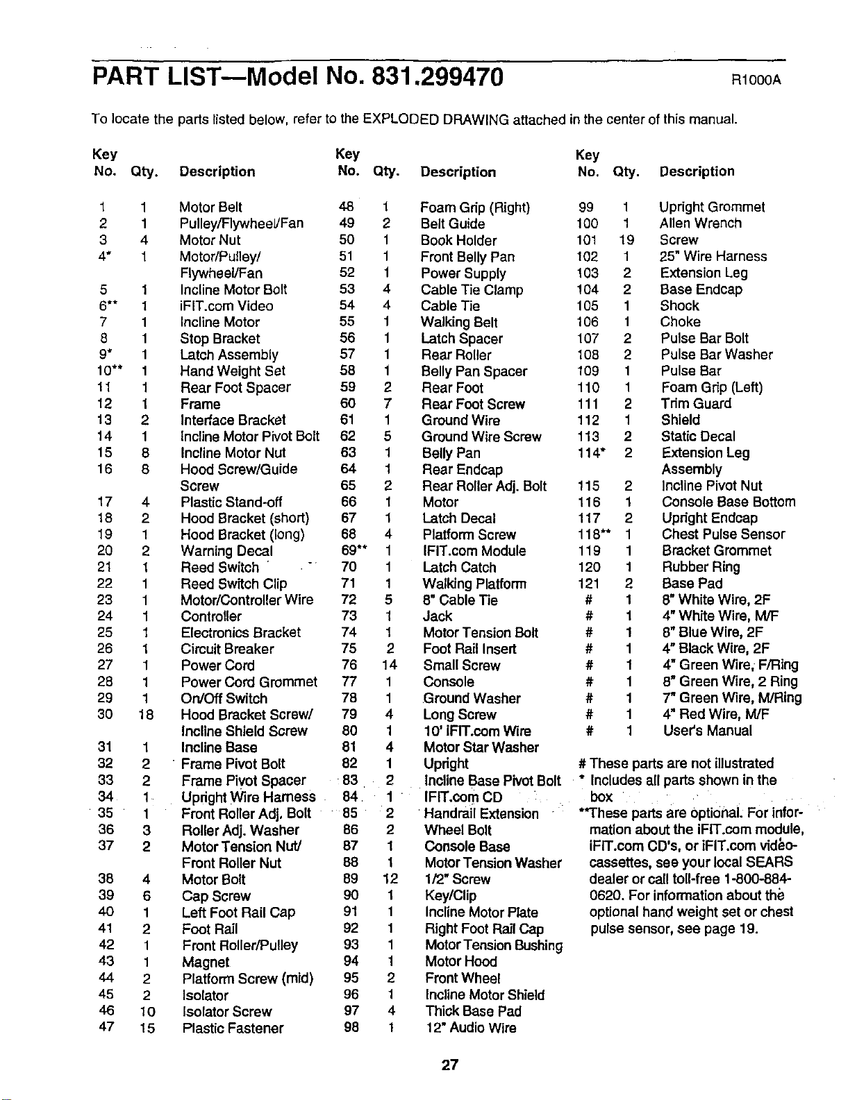
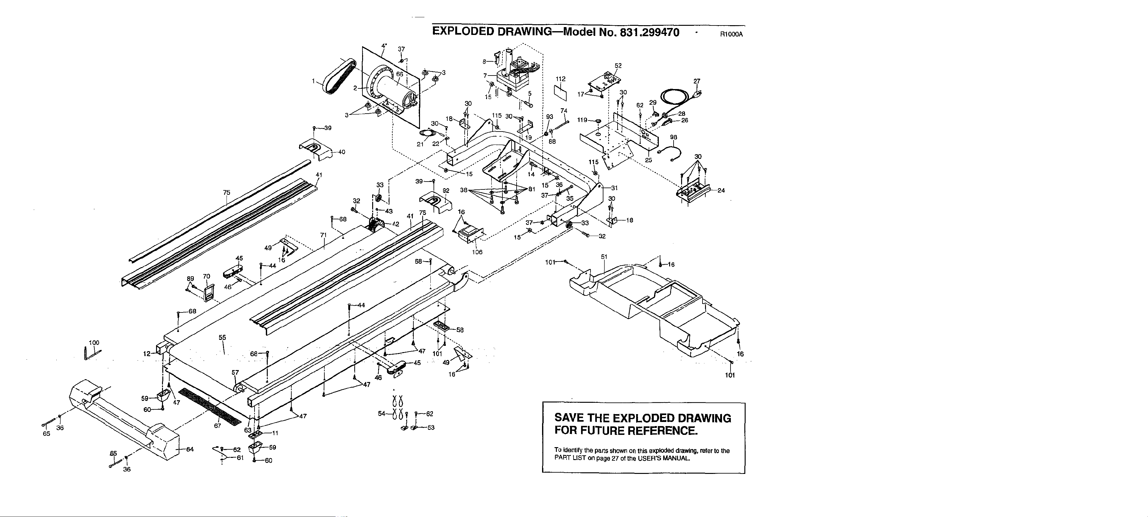
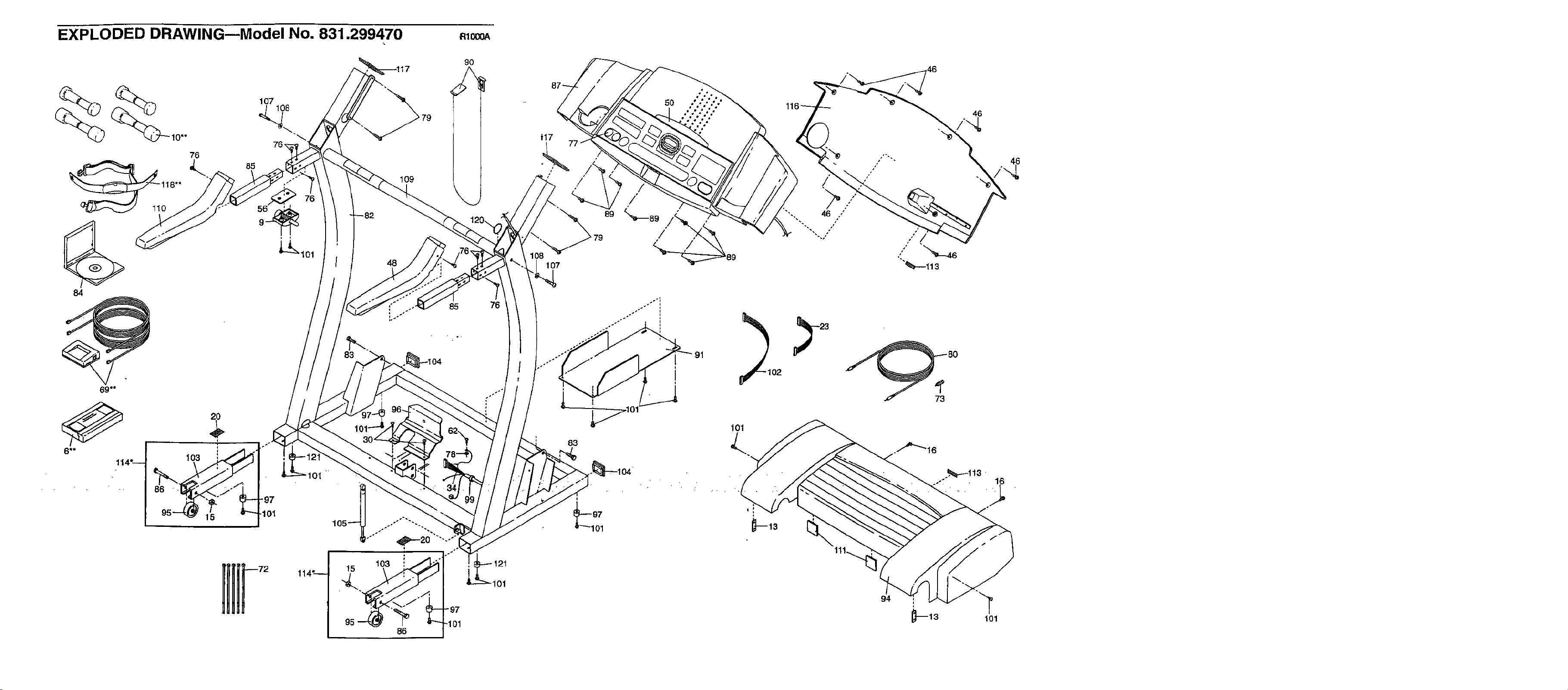
PART LIST--Model No. 831.299470
R1000A
To locate the parts listed below, refer to the EXPLODED DRAWING attached in the center of this manual.
Key Key Key
No. Q_. Description No. Q_. Description No. Q_. Description
1 1 Motor Belt 48 1
2 1 Pulley/Flywheel/Fan 49 2
3 4 Motor Nut 50 1
4* 1 Motor/pulley/ 51 1
Flywheel/Fan 52 1
5 1 Incline Motor Bolt 53 4
6** 1 iFIT.com Video 54 4
7 1 Incline Motor 55 1
8 1 Stop Bracket 56 1
9" 1 Latch Assembly 57 1
10"* 1 HandWeight Set 58 1
11 1 Rear Foot Spacer 59 2
12 1 Frame 60 7
13 2 Interface Bracket 61 1
14 1 Incline Motor Pivot Bolt 62 5
15 8 Incline Motor Nut 63 1
16 8 Hood Screw/Guide 64 1
Screw 65 2
17 4 Plastic Stand-off 66 1
18 2 Hood Bracket (short) 67 1
19 1 Hood Bracket (long) 68 4
20 2 Warning Decal 69** 1
21 1 Reed Switch " 70 1
22 1 Reed Switch Clip 71 1
23 1 Motor/Contreller Wire 72 5
24 1 Controller 73 1
25 1 Electronics Bracket 74 1
26 1 Cimuit Breaker 75 2
27 1 Power Cord 76 14
28 1 Power Cord Grommet 77 1
29 1 On/Off Switch 78 1
30 18 Hood Bracket Screw/ 79 4
Incline Shield Screw 80 1
31 1 Incline Base 81 4
32 2 " Frame Pivot Bolt 82 1
33 2 Frame Pivot Spacer 83 2
34 1 Updght Wire Harness 84 1
35 1 Front Roller Adj, Bolt 85 2
36 3 Roller Adj. Washer 86 2
37 2 Motor Tension Nut/ 87 1
Front Roller Nut 88 t
38 4 Motor Bolt 89 12
39 6 Cap Screw 90 1
40 1 Left Foot Rail Cap 91 1
41 2 Foot Rail 92 1
42 1 Front Roller/Pulley 93 1
43 1 Magnet 94 1
44 2 Platform Screw (mid) 95 2
46 2 Isolator 96 1
46 10 Isolator Screw 97 4
47 15 Plastic Fastener 98 1
Foam Grip (Right) 99 1 Upright Grommet
Belt Guide 100 1 Allen Wrench
Book Holder 101 19 Screw
Front Belly Pan 102 1 25" Wire Harness
Power Supply 103 2 Extension Leg
Cable Tie Clamp !04 2 Base Endcap
Cable Tie 105 1 Shock
Walking Belt 106 1 Choke
Latch Spacer 107 2 Pulse Bar Bolt
Rear Roller 108 2 Pulse Bar Washer
Belly Pan Spacer 109 1 Pulse Bar
Rear Foot 110 1 Foam Grip (Left)
Rear Foot Screw 111 2 Tdm Guard
Ground Wire 112 1 Shield
Ground Wire Screw 113 2 Static Decal
Belly Pan 114" 2 Extension Leg
Rear Endcap Assembly
Rear Roller Adj. Bolt 115 2 Incline Pivot Nut
Motor 116 1 Console Base Bottom
Latch Decal 117 2 Updght Endcap
Platform Screw 118"* 1 Chest Pulse Sensor
IFIT.com Module 119 1 Bracket Grommet
Latch Catch 120 1 Rubber Ring
Walking Platform 121 2 Base Pad
8" Cable Tie # 1 8"White Wire, 2F
Jack # 1 4" White Wire, M/F
Motor Tension Bolt # 1 8" Blue Wire, 2F
Foot Rail Insert # 1 4" Black Wire, 2F
Small Screw # 1 4" Green Wire, F/Ring
console # 1 8" Green Wire, 2 Ring
Ground Washer # 1 7" Green Wire, M/Ring
Long Screw # 1 4" Red Wire, M/F
10' iFIT.oom Wire # 1 User's Manual
Motor Star Washer
Updght # These parts are not illustrated
Incline Base Pivot Bolt * Includes all parts shown in the
IFIT.com CD box
Handrail Extension
Wheel Bolt
Console Base
Motor Tension Washer
lf2" Screw
Key/Clip
Incline Motor Plate
Right Foot Rail Cap
Motor Tension Bushing
Motor Hood
Front Wheel
Incline Motor Shield
Thick Base Pad
12" Audio Wire
**These parts are Optional. For Infor-
mation about the iFIT.com module,
iFIT.oom CD's, or iFIT.com video-
cassettes, see your local SEARS
dealer or call toll-free 1-800-884-
0620. For information about the
optional hand weight set or chest
pulse sensor, see page 19.
27
EXPLODED DRAWING--Model No. 831.299470
89
75
7O
45
41
32
71
16
4* 37
RIO00A
30
88
15
52
112 _0
74
30
51
27
62 29
98
3O
•-. 25
24
65
100
55
57
67
-58
101 16
SAVE THE EXPLODED DRAWING
FOR FUTURE REFERENCE.
To identifythe parts shownon this exploded drawing, refer to the
PART LIST on page 27 ofthe USER'S MANUAL.
101
EXPLODED DRAWINGmModel NO. 831.299470 Rlo_
9O
_ 107108
10"*
76_
76
118"*
0
84
15
85
101
"97
101
15
95
109
48
o
86
85
°
"97
.101
76
101
107
83
89
46
46
101

SE/ U S
Model No. 831.299470
QUESTIONS?
If you find that:
• you need help assembling or
operating the PROFORM
745CS treadmill
• a part is missing
• or you need to schedule repair
service
call our toll-free HELPLINE
1-800-736-6879
Monday-Saturday, 7 am-7 pm
Central Time (excluding holidays)
REPLACEMENT
PARTS
If parts become worn and need
to be replaced, call the following
toll-free number
1-800-FON-PART
(1-800-366-7278)
The model number and sedal number of your PROFORM e745CS
treadmill are listed on a decal attached to the frame. See the front
cover of this manual to find the location of the decal.
All replacement parts are available for immediate purchase or
special order when you visit your nearest SEARS Service Center.
To request service or to order parts by telephone, call the toIFfree
numbers listed at the left.
When requesting help or service, or ordering parts, please be
prepared to provide the following information:
• The NAME OF THE PRODUCT (PROFORM ° 745CS treadmill)
• The MODEL NUMBER OF THE PRODUCT (831.299470)
• The KEY NUMBER AND DESCRIPTION OF THE PART (see the
EXPLODED DRAWING in the center of this manual and the
PART LIST on page 27).
• . FULL 90 DAY WARRANTY
For 90 days from the date of purchase, iffailure occurs due to defect in material or workmanship inthis
SEARS TREADMILL EXERCISER, contact the nearest SEARS Service Center throughout the United
States and SEARS will repair or replace the TREADMILL EXERCISER, free of charge.
This warranty does not apply when the TREADMILL EXERCISER is'usedcommercially or for rental pur-
poses.
This warranty gives you specific legal rights, and you may also have other rights which vary from state
to state.
SEARS. ROEBUCK AND CO., DEPT. 817WA, HOFFMAN ESTATES, IL 60179
Part No. 169681 R1000A Pdnted In USA © 2000 Sears, Roebuck and Co.