Loading ...
Loading ...
Loading ...
-5-
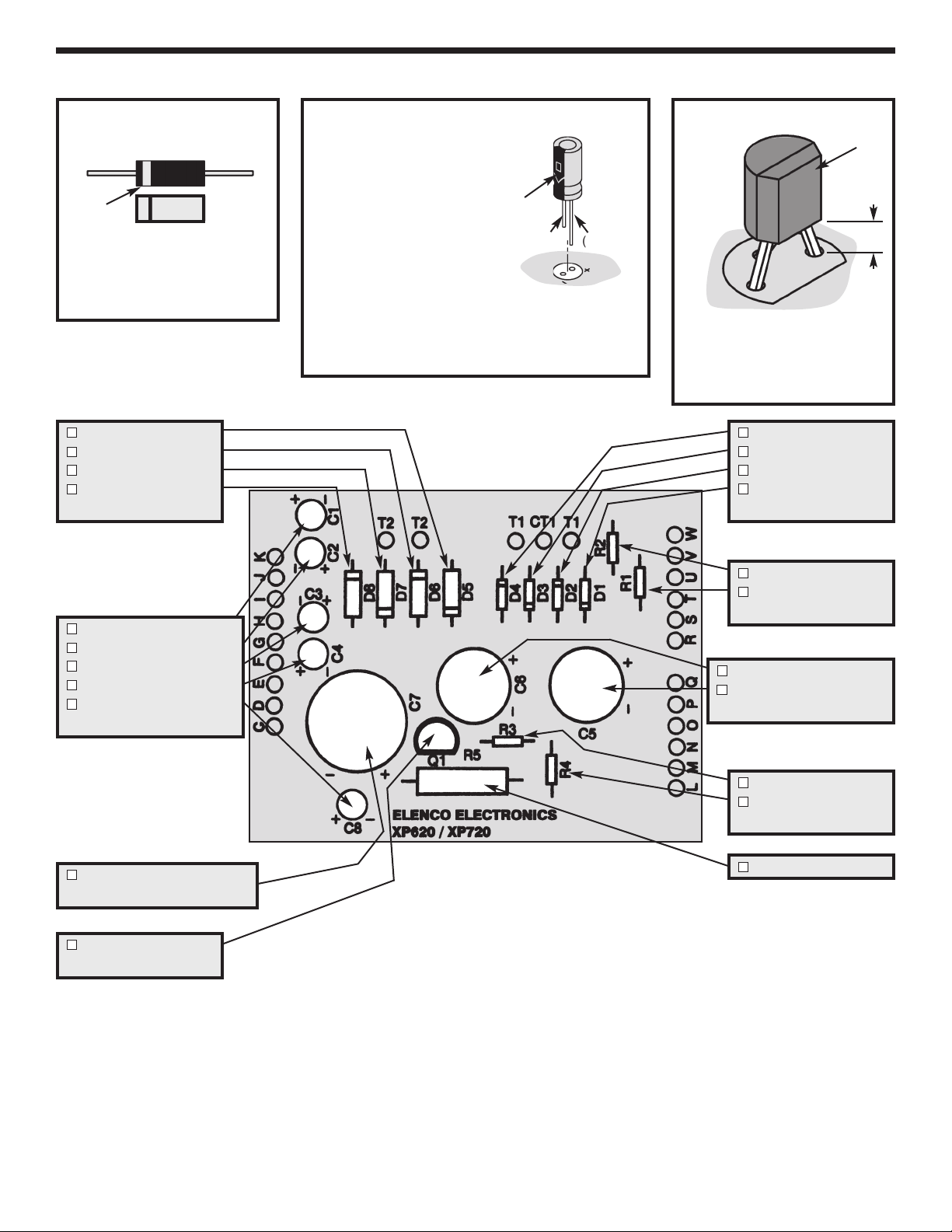
ASSEMBLE COMPONENTS TO PC BOARD
Figure A
Diodes have polarity. Be sure
that the band is in the correct
direction.
Figure B
Electrolytics have a
polarity marking
indicating the (–)
lead. The PC
board is marked to
show the lead
position.
Warning: If the capacitor is connected with
incorrect polarity it may heat up and either leak
or cause the capacitor to explode.
Figure C
Mount the transistor with the
flat side as shown on the top
legend. Leave 1/4” between
the part and PC board.
Band
D5 - 1N5400 Diode
D6 - 1N5400 Diode
D7 - 1N5400 Diode
D8 - 1N5400 Diode
(see Figure A)
C1 - 10mF Electrolytic
C2 - 10mF Electrolytic
C3 - 10mF Electrolytic
C4 - 10mF Electrolytic
C8 - 10mF Electrolytic
(see Figure B)
C7 - 4700mF Electrolytic
(see Figure B)
Q1 - A70 Transistor
(see Figure C)
D4 - 1N4001 Diode
D3 - 1N4001 Diode
D2 - 1N4001 Diode
D1 - 1N4001 Diode
(see Figure A)
R2 - 150W Resistor
R1 - 150W Resistor
(brn-green-brn-gold)
C6 - 2200mF Electrolytic
C5 - 2200mF
Electrolytic
(see Figure B)
R3 - 2.7W Resistor
R4 - 2.7W Resistor
(red-violet-gold-gold)
R5 - .18W Resistor
Flat
1/4”
(–) (+)
Polarity
Mark
XP-720K_REV-H_111114.qxp_XP-720K REV-H 111114 7/31/15 1:07 PM Page 6
Loading ...
Loading ...
Loading ...