Loading ...
Loading ...
Loading ...
-10-
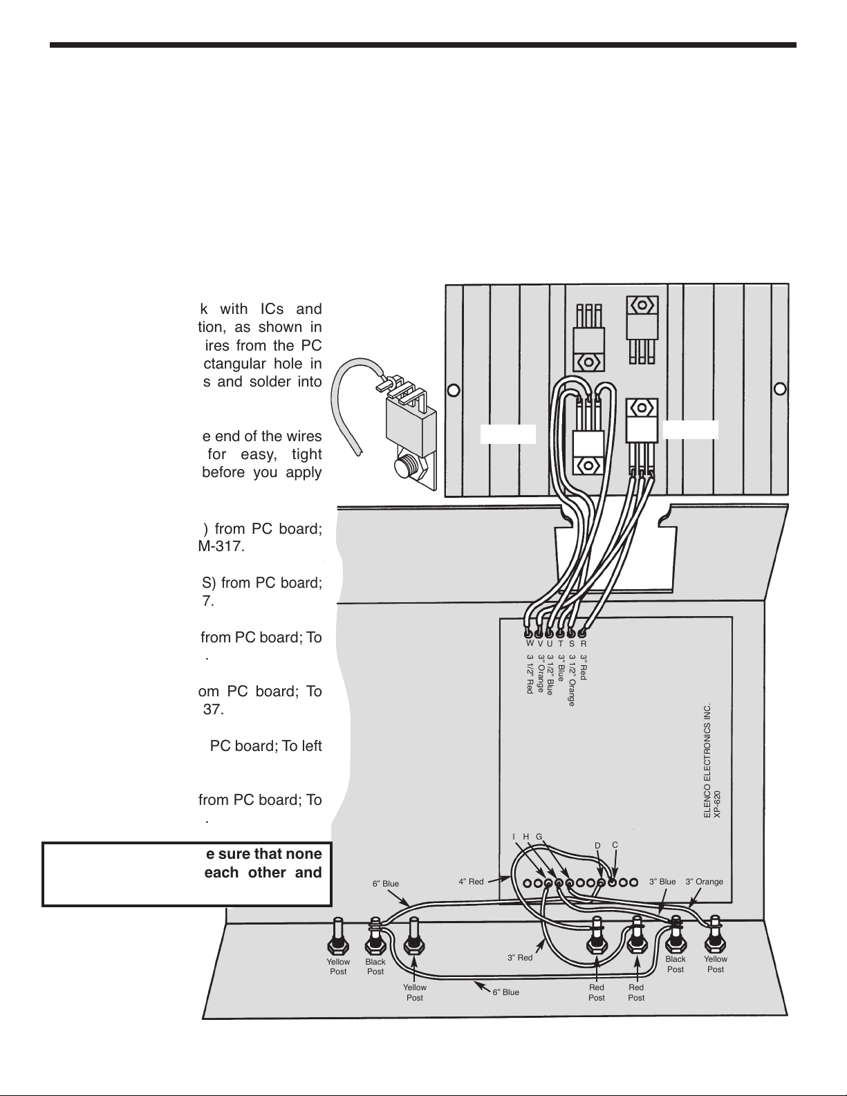
WIRE BINDING POSTS AND 317, 337
Solder the wires from the board to the binding posts, as shown in Figure K.
r 3” Orange wire from (G) on the PC board; To the Yellow post (–1.25 - 15V).
r 4” Blue wire from (H) on the PC board and the 6” blue wire from the black AC binding post; To the Black post
(common).
r 3” Red wire from (I) on the PC board; To the Red post (+1.25 - 15V).
r 4” Red wire from (C) on the PC board; To the Red post (+5V 3A).
Place the heat sink with ICs and
transistor in the position, as shown in
Figure K. Insert the wires from the PC
board, through the rectangular hole in
the chassis, to the ICs and solder into
place.
Tin the leads. Form the end of the wires
into a tight loop, for easy, tight
connection to leads, before you apply
solder.
r 3 1/2” Red wire (W) from PC board;
To middle lead of LM-317.
r
3 1/2” Orange wire (S) from PC board;
To left lead of LM-317.
r 3 1/2” Blue wire (U) from PC board; To
right lead of LM-317.
r 3” Red wire (R) from PC board; To
middle lead of LM-337.
r 3” Blue wire (T) from PC board; To left
lead of LM-337.
r 3” Orange wire (V) from PC board; To
right lead of LM-337.
After wiring the ICs, be sure that none
of the leads touch each other and
cause a short.
Figure K
W
V
U
T
S
R
3 1/2” Red
3” Orange
3 1/2” Blue
3” Blue
3 1/2” Orange
3” Red
I
H
G
D
C
Black
Post
Yellow
Post
6” Blue
6” Blue
3” Red
Red
Post
Black
Post
Yellow
Post
3” Orange
3” Blue
ELENCO ELECTRONICS INC.
XP-620
Yellow
Post
Red
Post
4” Red
LM-317
LM-337
XP-720K_REV-H_111114.qxp_XP-720K REV-H 111114 7/31/15 1:08 PM Page 11
Loading ...
Loading ...
Loading ...