Loading ...
Loading ...
Loading ...
-14-
CIRCUIT DESCRIPTION
Introduction
T
he Model XP-720 Power Supply features three solid-state DC power supplies and a 12.6VAC center-tapped
o
utput. The first two supplies consist of one positive and one negative 1.25 to 15 volts at 1 ampere. The third
h
as a fixed 5V at 3 amperes. All DC supplies are fully regulated. A special IC circuit keeps the output voltage
within 0.2V when going from no load to full load. The output is fully protected from short circuits. This supply is
ideal for use in school labs, service shops or anywhere a precise DC voltage is required. The AC section has
6.3VAC @ 1A and a 12.6 center tapped @ 1A.
The Positive 1.25-15V Power Supply
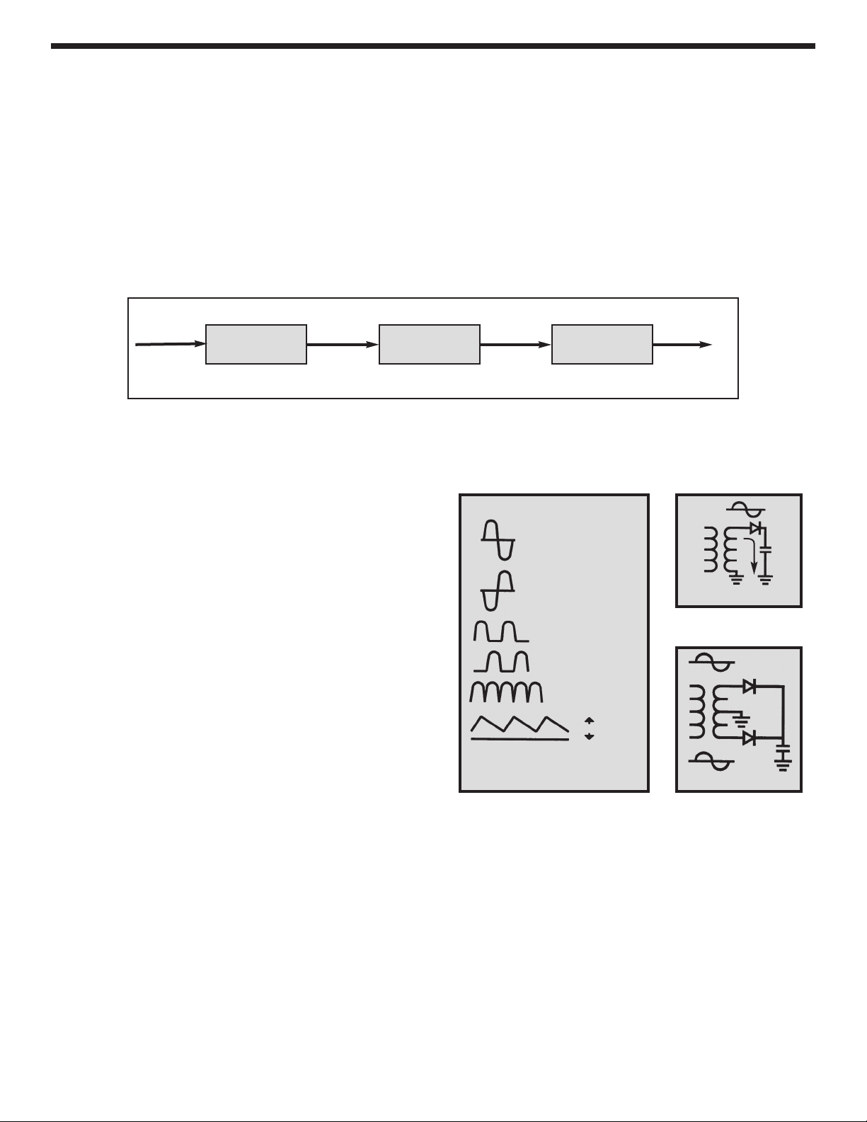
Figure 1 shows a simplified circuit diagram of the positive supply. It consists of a power transformer, a DC
rectifier stage and the regulator stage.
Transformer
The transformer T1 serves two purposes. First, it
reduces the 120VAC input to 17VAC to allow the
proper voltage to enter the rectifier stages. Second, it
isolates the power supply output from the 120VAC
line. This prevents the user from dangerous voltage
shock should the user be standing in a grounded
area.
AC to DC Converter
The AC to DC converter consists of diodes D1 and D2
and capacitor C1. Transformer T1 has two secondary
windings which are 180 degrees out of phase. The AC
output at each winding is shown in Figure 2A and 2B.
Diodes are semiconductor devices that allow current
to flow in one direction. The arrow in Figure 3 points
to the direction that the current will flow. Only when
the transformer voltage is positive will current flow
through the diodes. Figure 3 shows the simplest
possible rectifier circuit. This circuit is known as a half-
wave rectifier. Here the diode conducts only half of the
time when the AC wave is positive as shown in Figure
2C. Use of this circuit is simple but inefficient. The big gap between cycles require much more filtering to obtain
a smooth DC voltage.
By addition of a second diode and transformer winding, we can fill in the gap between cycles as shown in
Figure 4. This circuit is called full-wave rectification. Each diode conducts when the voltage is positive. By
adding the two outputs, the voltage presented to capacitor C1 is more complete, thus easier to filter, as shown
in Figure 2E. When used in 60 cycles AC input power, the output of a full wave rectifier will be 120 cycles.
Capacitor C1 is used to store the current charges, thus smoothing the DC voltage. The larger the capacitor, the
more current is stored. In this design, 2200mF capacitors are used, which allows about 3 volts AC ripple when
one amp is drawn.
Figure 1
Simplified diagram of positive power supply
120VAC
Input
17VAC 20VDC
1.25 - 15V
Regulated
Output
Transformer
120V to 17V
AC to DC
Converter
Voltage
Regulator
Figure 2
Figure 3
Figure 4
Voltage Waveform for Supply
A) Transformer
Winding AB
B) Transformer
Winding BC
C) Output of
diode D1.
D) Output of
diode D2.
E) Total of diodes
D1 & D2.
20V
F) Output of capacitor C1
Ripple depends on load
current (expanded).
Half Wave Rectifier
Full Wave Rectifier
D1
D2
C1
C1
D1
XP-720K_REV-H_111114.qxp_XP-720K REV-H 111114 7/31/15 1:08 PM Page 15
Loading ...
Loading ...
Loading ...