Loading ...
Loading ...
Loading ...
-11-
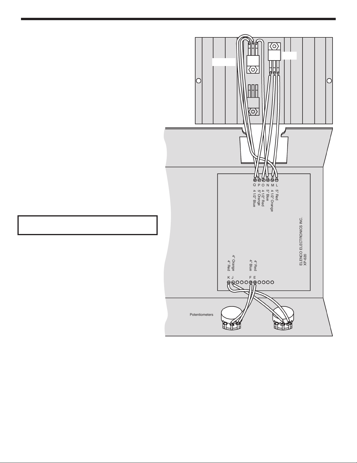
WIRE 2N6124, 7805 & POTENTIOMETERS
I
nsert the wires from the PC board through the
rectangular hole in the chassis to the 2N6124
a
nd LM-7805, solder into place, as shown in
Figure L.
r 5” Red wire (L) from the PC board; To
middle lead 0f 2N6124.
r 5” Orange wire (P) from the PC board; To
left lead of 2N6124.
r 5” Blue wire (N) from the PC board; To right
lead of 2N6124.
r 4 1/2” Red wire (O) from PC board; To
middle lead of LM-7805.
r 4 1/2” Blue wire (Q) from PC board; To left
lead of LM-7805.
r 4 1/2” Orange Wire (M) from PC board; To
right lead of LM-7805.
After wiring, be sure that the leads do not touch
each other and cause a short.
Solder the wires from the PC board to the
potentiometers, as shown in Figure L.
r 4” Red wire (E) from PC board; To middle
lug of the positive voltage pot.
r 4” Blue wire (F) from PC board; To right lug
on the positive voltage pot.
r 4” Orange wire (J) from PC board; To middle
lug on the negative voltage pot.
r 4” Red wire (K) from PC board; To right lug
on negative voltage pot.
4 1/2” Blue
5” Orange
4 1/2” Red
5” Blue
4 1/2” Orange
5” Red
ELENCO ELECTRONICS INC.
XP-620
4” Blue
4” Red
EF
JK
4” Red
4” Orange
Negative VoltagePositive Voltage
Potentiometers
Figure L
Q
P
O
N
M
L
2N6124
7805
XP-720K_REV-H_111114.qxp_XP-720K REV-H 111114 7/31/15 1:08 PM Page 12
Loading ...
Loading ...
Loading ...