Loading ...
Loading ...
Loading ...
Accu-Steam™ Installation and Owners Manial
MP5004-1202 PAGE 20
INSTALLATION PROCEDURE
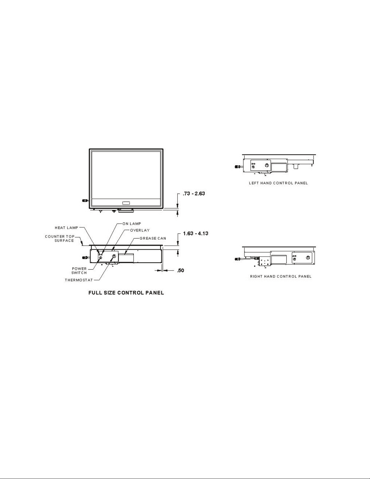
5. The dimensional relationship between the griddle module mounting ange and
the control panel module is shown in Figure 3. The griddle module mounting
ange overlaps the countertop cutout by 0.50 inches on all four sides. Mark the
griddle module cutout on the countertop such that the front edge of the griddle
module is 0.73 inches – 2.63 inches from the control panel module mounting
surface, as shown in Figure 3. Mark the control panel module cutout on the
control panel module mounting surface, as shown in Figure 2.
6. Cut out the griddle and control panel module openings. Straighten out any dings or bent
edges in both cutouts to ensure adequate sealing between the new griddle and the counter
top surface and between the control panel and the front surface of the counter.
7. Drill the mounting holes in the face of the counter using a #25 drill bit. Drill the rst set
of holes and locate the remaining holes using the control panel as a template.
8. Use a lifting device, if possible, to raise the griddle module above the counter and position
over cutout in countertop. Lower the griddle module carefully into the cutout. Install the
retainer clamps to the griddle module, using the ¼-20 nylock nuts (see drawing AT2A-
3044, sheet 6).
9. Install the control panel onto the counter face using #10-24 x 3/8 inch self-tapping screws.
Also, at this time, install the thermostat knob guard, if necessary, by lining up the holes on
the guard to the holes on the control panel directly above and below the thermostat.
INSTALLATION DROP-IN GRIDDLE (cont.)
MODEL EGD
Loading ...
Loading ...
Loading ...