Loading ...
Loading ...
Loading ...
8
NOTE:
Only non-combustible materials can be used in close proximity to this appliance.
To facilitate easy operation, drainage and servicing of appliance, a minimum of
600mm clearance should be maintained at front of appliance.
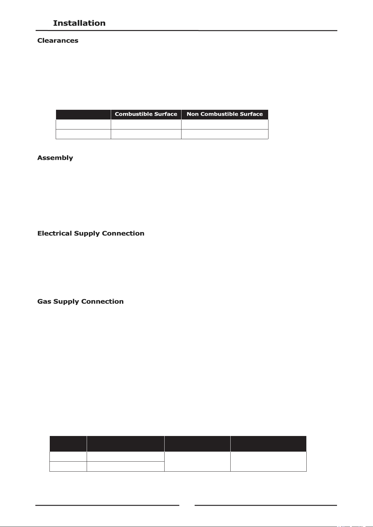
Any gas burning appliance requires adequate clearance and ventilation for optimum and trouble-free
operation. The following minimum installation clearances are to be adhered to:
This model is delivered completely assembled. Ensure that the legs are securely attached.
NOTE: This appliance is fitted with adjustable feet to enable appliance to be positioned securely
and level on uneven floors. This should be carried out on completion of gas connection.
Refer to 'Gas Connection' section below.
Optional Accessories (Refer to Replacement Parts List)
Plinth Kit. For installation details, refer to instructions supplied with each kit.
NOTE: ALL ELECTRICAL CONNECTION MUST ONLY BE CARRIED OUT BY A QUALIFIED PERSON.
1. Each appliance should be connected to an adequately protected power supply and isolation switch
mounted adjacent to, but not behind appliance. This switch must be clearly marked and readily
accessible in case of fire.
2. Check electricity supply is correct as shown on Rating Plate attached to inside of access door.
3. For immediate electrical supply, simply plug lead into a properly earthed, 3 pin socket.
NOTE: ALL GAS FITTING MUST ONLY BE CARRIED OUT BY AN AUTHORISED PERSON.
This appliance can be configured to have underside or rear entry gas supply.
To convert this appliance, see the Gas Supply Connection Location Conversion section of this manual
for instructions.
Flexible Hose Connection
If a Gas Hose assembly is used to connect this appliance, hose and all fittings must have a minimum
¾” (Natural Gas) or ½” (LPG) inside bore diameter to ensure gas flow rate capacity required by this
appliance is achieved.
This must be verified by operating pressure testing at maximum gas supply demand condition.
Gas Hose assembly should also be classified for use in commercial kitchen conditions that appliance
will be used in.
Recommended Gas Hose Assembly Specification:
- AS/NZS 1869 Class B or D compliant or equivalent, that meets the following requirements:-
Left / Right Hand Side
50mm. 0mm.
Rear
50mm. 0mm.
Class
Max Working Pressure
at 23 ± 2ºC
Working Temperature
Range
Resistance to Oil
B
7.0 kPa
- 20ºC to + 125ºC
Oil resistant lining and cover.
D
2.6 MPa
Loading ...
Loading ...
Loading ...