Loading ...
Loading ...
Loading ...
4
How to Use Snap Circuits
®
Snap Circuits
®
uses building blocks with snaps
to build the different electrical and electronic
circuits in the projects. Each block has a
function: there are switch blocks, light blocks,
battery blocks, different length wire blocks,
etc. These blocks are different colors and
have numbers on them so that you can easily
identify them. The blocks you will be using are
shown as color symbols with level numbers
next to them, allowing you to easily snap them
together to form a circuit.
For Example:
This is the switch block which is green and has
the marking on it. The part symbols in this
booklet may not exactly match the appearance
of the actual parts, but will clearly identify them.
This is a wire block which is blue and comes in
different wire lengths.
This one has the number , , , ,
or on it depending on the length of the wire
connection required.
There is also a 1-snap wire that is used as a
spacer or for interconnection between different
layers.
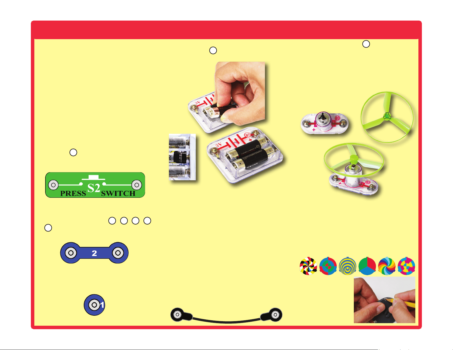
You need a power source to build each circuit.
This is labeled and requires two (2) 1.5V
“AA” batteries (not included).
When installing a battery, be sure the spring
is compressed straight back, and not bent up,
down, or to one side.
A large clear plastic base grid is included with
this kit to help keep the circuit blocks properly
spaced. You will see evenly spaced posts that
the different blocks snap into. The base has
rows labeled A-G and columns labeled 1-10.
Next to each part in every circuit drawing is
a small number in black. This tells you which
level the component is placed at. Place all
parts on level 1 rst, then all of the parts on
level 2, then all of the parts on level 3, etc.
Some circuits use the jumper wires to make
unusual connections. Just clip them to the
metal snaps or as indicated.
Usually when the motor is used, the glow
fan will usually be placed on it. On top of the
motor shaft is a black plastic piece (the motor
top) with three little tabs. Lay the fan on the
black piece so the slots in its bottom “fall into
place” around the three tabs in the motor top.
If not placed properly, the fan will fall off when
the motor starts to spin.
This set contains 6 pre-punched cardboard
discs. These will be used with a strobe light
in project 46 and others. The discs may be
supplied as a single sheet; just punch them
out.
To remove a disc from the holder, use your
ngernail, or use a pencil to push it up from
beneath one of the tabs.
S2
2
3 4 5
6
B1
M1
Loading ...
Loading ...
Loading ...