1
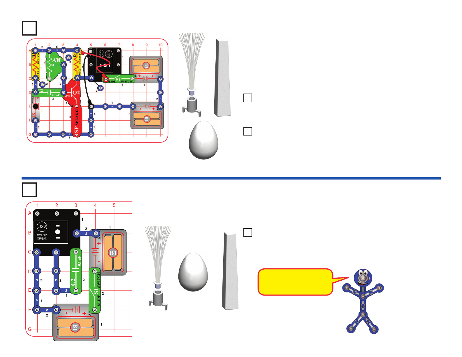
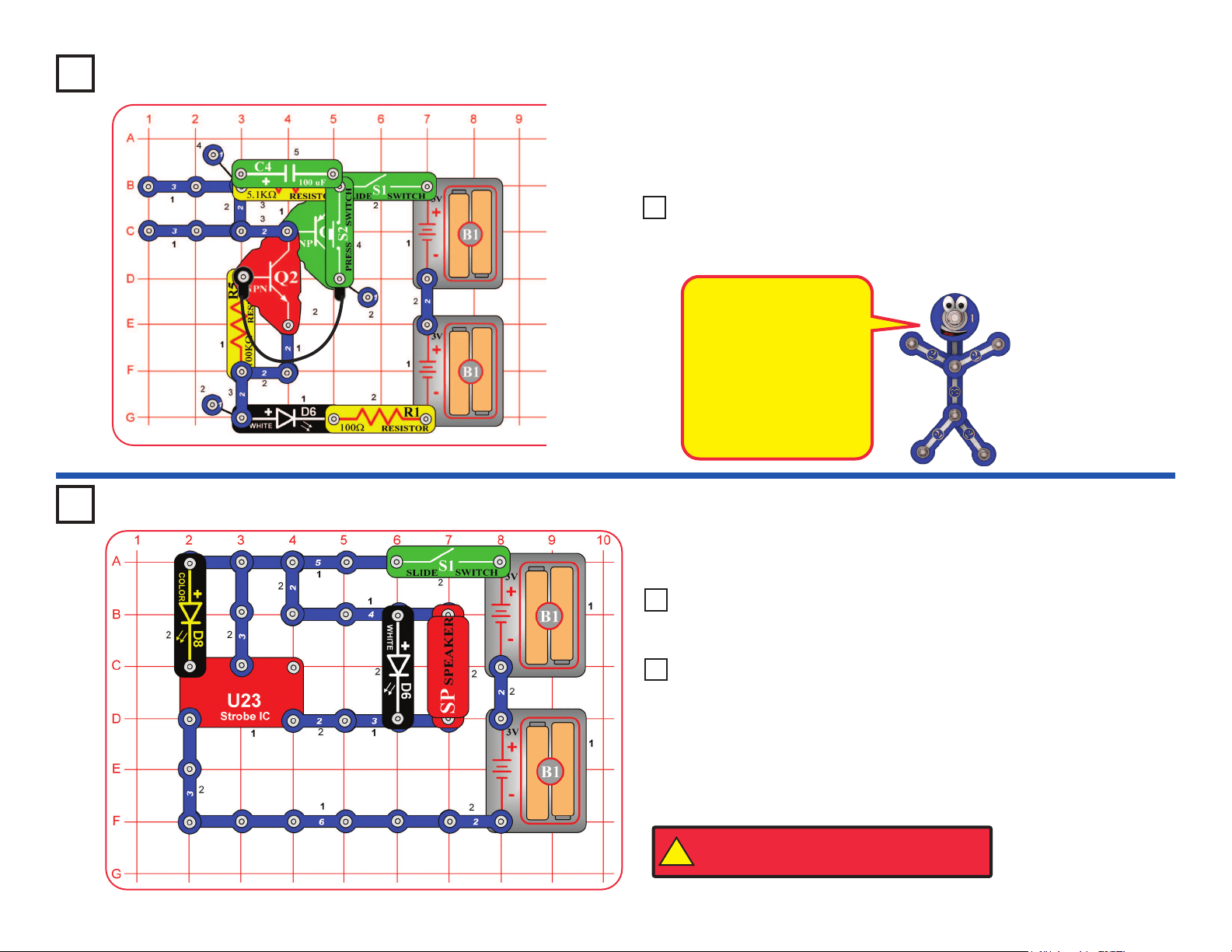
Project 22
Go to https://shop.elenco.com/
consumers/snap-circuits-light.html
to download projects 84-177
and Bonus Projects 1-11!
Copyright
©
2021 by Elenco
®
Electronics, Inc. All rights reserved. No part of this book shall be reproduced
by any means; electronic, photocopying, or otherwise without written permission from the publisher.
SOURCE CODE:SCL-175V1 | REV-B | 753285
1
1. Most circuit problems are due to incorrect assembly,
always double-check that your circuit exactly matches
the drawing for it.
2. Be sure that parts with positive/negative markings are
positioned as per the drawing.
3. Be sure that all connections are securely snapped.
4. Try replacing the batteries.
5. If the motor spins but does not balance the fan, check
the black plastic piece with three prongs on the motor
shaft, and replace it if it is damaged (this kit includes
a spare). To replace, pry the broken one off the motor
shaft using a screwdriver, then push the new one on.
6. If aberopticscircuitisn’tworking, make sure the
clear & black cable holders are pushed all the way
ontotheLED/phototransistor,andtheberopticcable
is pushed into the holders as far as it will go. The cable
should be standing straight up in the holders.
ELENCO
®
is not responsible for parts damaged due to
incorrect wiring.
Basic Troubleshooting
Note: If you suspect you have damaged parts, you can follow the
Advanced Troubleshooting procedure on page 14 to determine which ones
need replacing.
Basic Troubleshooting 1
Parts List 2-3
How to Use Snap Circuits
®
4-5
About Your Snap Circuits
®
LIGHT Parts
6-8
Introduction to Electricity 9
Light in Our World 10-12
DO’sandDON’TsofBuildingCircuits 13
Advanced Troubleshooting 14-15
Projects 1 - 83 16-42
WARNING: SHOCK HAZARD - Never connect Snap
Circuits
®
to the electrical outlets in your home in any way!
Table of Contents
WARNING: Always check your wiring
before turning on a circuit. Never leave a
circuit unattended while the batteries are
installed. Never connect additional batteries
or any other power sources to your circuits.
Discard any cracked or broken parts.
Adult Supervision: Because children’s
abilities vary so much, even with age
groups, adults should exercise discretion as
to which experiments are suitable and safe
(the instructions should enable supervising
adults to establish the experiment’s
suitability for the child). Make sure your
child reads and follows all of the relevant
instructions and safety procedures, and
keeps them at hand for reference.
This product is intended for use by adults
and children who have attained sufcient
maturity to read and follow directions and
warnings.
Never modify your parts, as doing so may
disable important safety features in them,
and could put your child at risk of injury.
CAUTION: Persons who are extremely
sensitive to flashing lights and rapidly
changing colors or patterns should exercise
caution when playing with this toy.
CAUTION: High intensity light. Do not look
directly at white LED (D6).
WARNING FOR ALL PROJECTS WITH A SYMBOL - Moving parts. Do not touch the motor or fan during operation.
Do not lean over the motor. Do not launch the fan at people, animals, or objects. Eye protection is recommended.
!
!
!
● Use only 1.5V “AA” type, alkaline batteries
(not included).
● Insert batteries with correct polarity.
● Non-rechargeable batteries should not be
recharged. Rechargeable batteries should
only be charged under adult supervision, and
should not be recharged while in the product.
● Do not mix old and new batteries.
● Do not connect batteries or battery holders in
parallel.
● Do not mix alkaline, standard (carbon-zinc),
or rechargeable (nickel-cadmium) batteries.
● Remove batteries when they are used up.
● Do not short circuit the battery terminals.
●Neverthrowbatteriesinareorattemptto
open its outer casing.
● Batteries are harmful if swallowed, so keep
away from small children.
Batteries:
!
WARNING: CHOKING HAZARD -
Small parts. Not for children under 3 years.
!
Conforms to all applicable
government requirements
Go to https://shop.elenco.com/
consumers/snap-circuits-light.html
to download projects 84-177
and Bonus Projects 1-11!
2
Important: If any parts are missing or damaged, DO NOT RETURN TO RETAILER. Call toll-free (800) 533-2441 or e-mail us at: help@
elenco.com. Customer Service • 150 Carpenter Ave. • Wheeling, IL 60090 U.S.A.
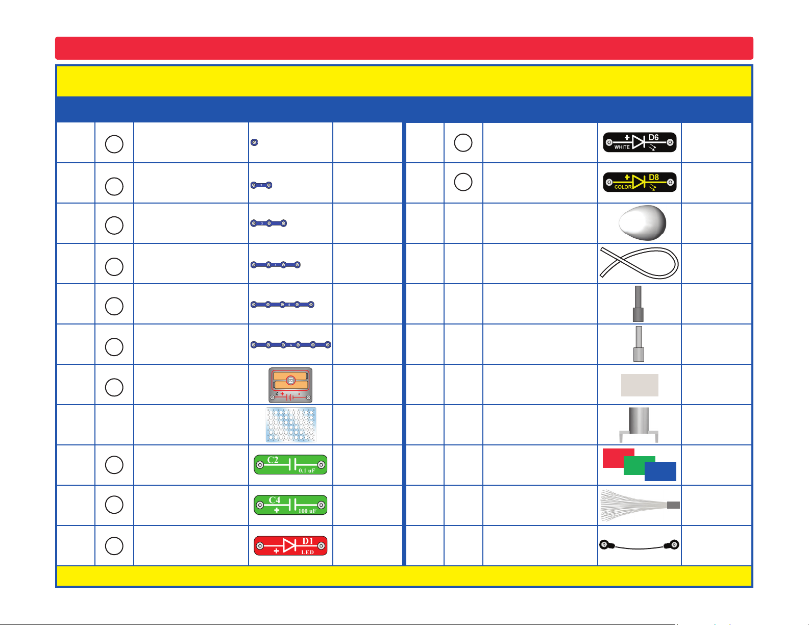
Parts List (Colors and styles may vary) Symbols and Numbers (page 1)
Qty. ID Name Symbol Part # Qty. ID Name Symbol Part #
r 3 1-Snap Wire 6SC01 r 1
White Light Emitting
Diode (LED)
6SCD6
r 6 2-Snap Wire 6SC02 r 1
Color Light Emitting
Diode (LED)
6SCD8
r 3 3-Snap Wire 6SC03 r 1 Egg LED Attachment 6SCEGG
r 1 4-Snap Wire 6SC04 r 1 Fiber Optic Cable 6SCFC
r 1 5-Snap Wire 6SC05 r 1
Fiber Optic Cable
Holder, black
6SCFCHB
r 1 6-Snap Wire 6SC06 r 1
Fiber Optic Cable
Holder, clear
6SCFCHC
r 2
Battery Holder - uses
two (2) 1.5V type “AA”
(not Included)
6SCB1 r 1 Prismatic Film 6SCFILM
r 1
Base Grid
(11.0” x 7.7”)
6SCBG r 1
Mounting Base
(for ber optic tree)
6SCFMB
r 1 0.1mF Capacitor 6SCC2
r 1
Red/Green/Blue
Filters Set
6SCFRGB
r 1 100mF Capacitor 6SCC4 r 1 Fiber Optic Tree 6SCFT
r 1
Red Light Emitting
Diode (LED)
6SCD1
r 1 Jumper Wire (black) 6SCJ1
You may order additional / replacement parts at our website: www.elenco.com/replacement-parts/
5
4
3
2
1
C2
D1
C4
6
B1
D8
D6
3
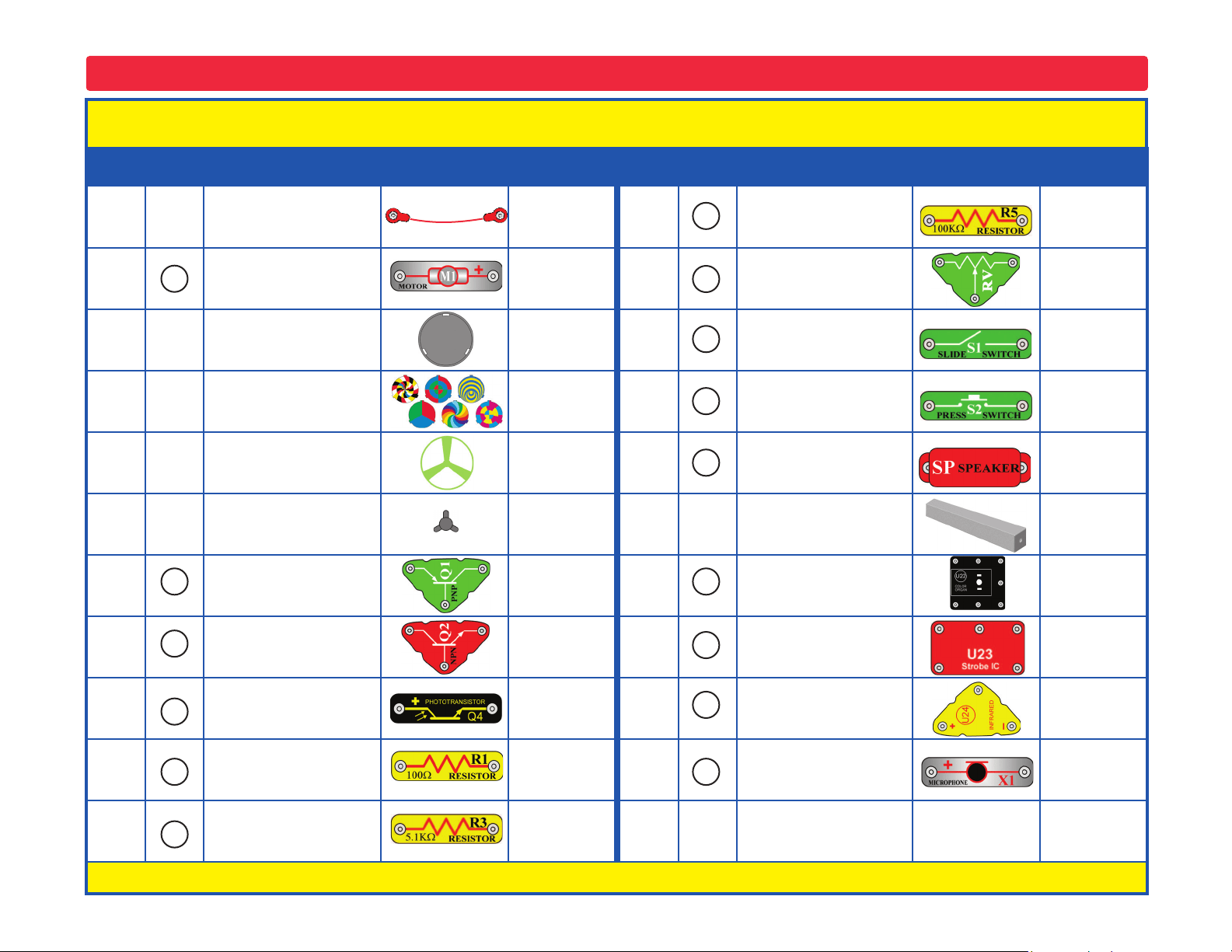
Important: If any parts are missing or damaged, DO NOT RETURN TO RETAILER. Call toll-free (800) 533-2441 or e-mail us at: help@
elenco.com. Customer Service • 150 Carpenter Ave. • Wheeling, IL 60090 U.S.A.
Parts List (Colors and styles may vary) Symbols and Numbers (page 2)
Qty. ID Name Symbol Part # Qty. ID Name Symbol Part #
r 1 Jumper Wire (red) 6SCJ2 r 1 100kW Resistor 6SCR5
r 1 Motor 6SCM1 r 1 Adjustable Resistor 6SCRV
r 1 Disc Holder 6SCM1DH r 1 Slide Switch 6SCS1
r 1
Set of Disc Cutouts
(6 pcs. / set)
6SCM1DS r 1 Press Switch 6SCS2
r 1 Glow Fan Blade 6SCM1FG r 1 Speaker 6SCSP
r 1 Spare Motor Top 6SCM1T r 1
Tower LED
Attachment
6SCTOWER
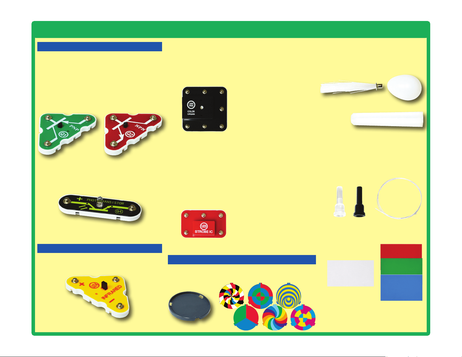
r 1 PNP Transistor 6SCQ1 r 1 Color Organ 6SCU22
r 1 NPN Transistor 6SCQ2
r 1 Strobe IC 6SCU23
r 1 Phototransistor 6SCQ4 r 1 Infrared Receiver 6SCU24
r 1 100W Resistor 6SCR1 r 1 Microphone 6SCX1
r 1 5.1kW Resistor 6SCR3
You may order additional / replacement parts at our website: www.elenco.com/replacement-parts/
S1
RV
R5
R3
R1
X1
U22
S2
SP
U24
U23
Q4
M1
Q1
Q2
4
How to Use Snap Circuits
®
Snap Circuits
®
uses building blocks with snaps
to build the different electrical and electronic
circuits in the projects. Each block has a
function: there are switch blocks, light blocks,
battery blocks, different length wire blocks,
etc. These blocks are different colors and
have numbers on them so that you can easily
identify them. The blocks you will be using are
shown as color symbols with level numbers
next to them, allowing you to easily snap them
together to form a circuit.
For Example:
This is the switch block which is green and has
the marking on it. The part symbols in this
booklet may not exactly match the appearance
of the actual parts, but will clearly identify them.
This is a wire block which is blue and comes in
different wire lengths.
This one has the number , , , ,
or on it depending on the length of the wire
connection required.
There is also a 1-snap wire that is used as a
spacer or for interconnection between different
layers.
You need a power source to build each circuit.
This is labeled and requires two (2) 1.5V
“AA” batteries (not included).
When installing a battery, be sure the spring
is compressed straight back, and not bent up,
down, or to one side.
A large clear plastic base grid is included with
this kit to help keep the circuit blocks properly
spaced. You will see evenly spaced posts that
the different blocks snap into. The base has
rows labeled A-G and columns labeled 1-10.
Next to each part in every circuit drawing is
a small number in black. This tells you which
level the component is placed at. Place all
parts on level 1 rst, then all of the parts on
level 2, then all of the parts on level 3, etc.
Some circuits use the jumper wires to make
unusual connections. Just clip them to the
metal snaps or as indicated.
Usually when the motor is used, the glow
fan will usually be placed on it. On top of the
motor shaft is a black plastic piece (the motor
top) with three little tabs. Lay the fan on the
black piece so the slots in its bottom “fall into
place” around the three tabs in the motor top.
If not placed properly, the fan will fall off when
the motor starts to spin.
This set contains 6 pre-punched cardboard
discs. These will be used with a strobe light
in project 46 and others. The discs may be
supplied as a single sheet; just punch them
out.
To remove a disc from the holder, use your
ngernail, or use a pencil to push it up from
beneath one of the tabs.
S2
2
3 4 5
6
B1
M1
5
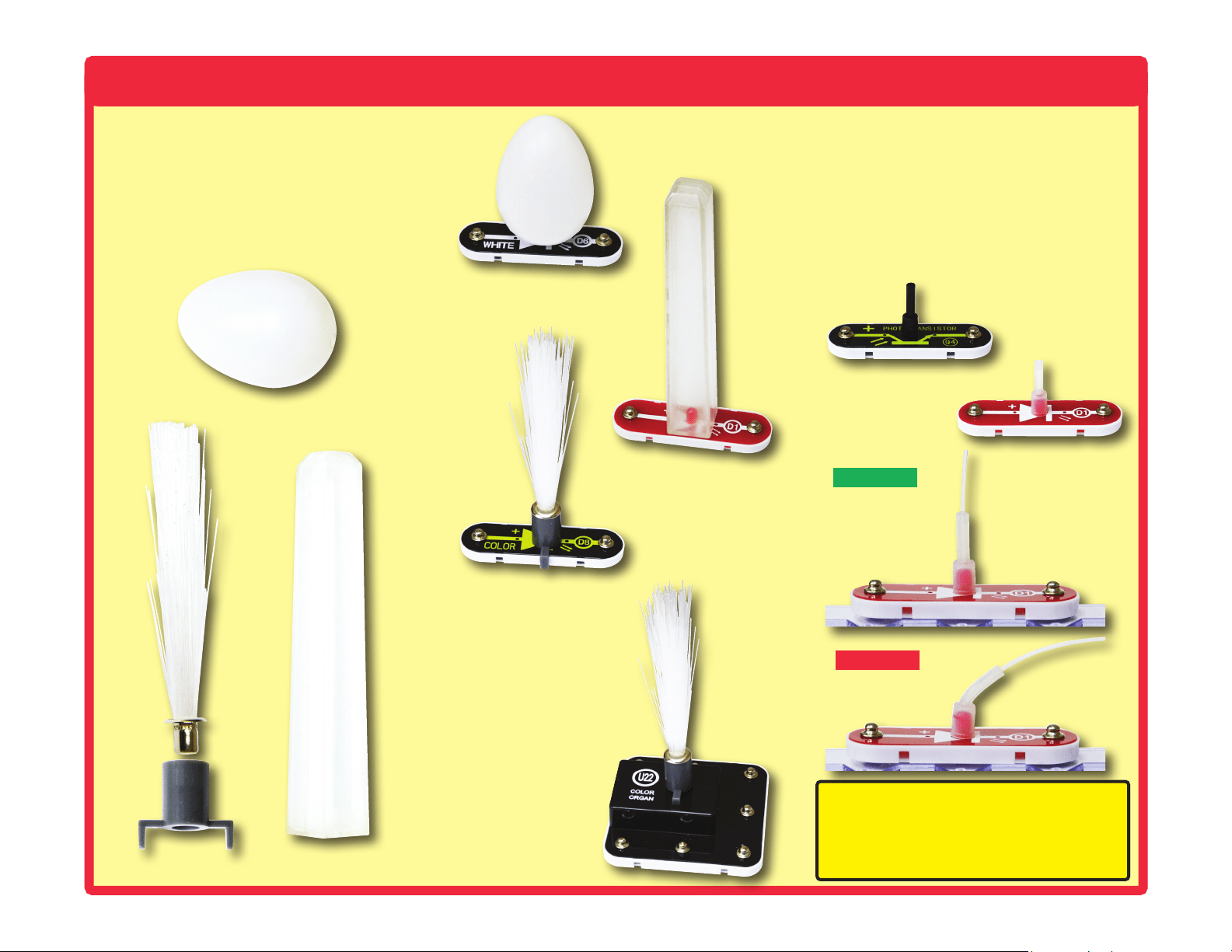
How to Use Snap Circuits
®
This set contains three LED attachments,
which can be mounted on the LED modules
(D1, D6, D8, and on U22) to enhance their
light effects. The egg and tower attachments
are mounted directly on the LEDs, but the
ber optic tree must be mounted using the
mounting base, as shown. This is described
in the projects.
In some projects, the ber optic cable will be
mounted on the LEDs (D1, D6, D8, and on
U22) or the phototransistor (Q4). This is done
by placing the clear and black cable holders
onto the LED/phototransistor, then inserting
the ber optic cable all the way into the holder.
For best performance the cable should stand
straight up in the holders, without bending
them. This is described in the projects.
Light Tower
Correct
Incorrect
Fiber Optic Tree
LED attachment
mounted to D8
Light Tower
LED attachment
mounted to D1
Fiber Optic Tree
LED attachment
mounted to U22
Egg LED attachment
mounted to D6
Note: While building the projects, be
careful not to accidentally make a direct
connection across the battery holder (a
“short circuit”), as this may damage and/or
quickly drain the batteries.
Egg
Fiber Optic Tree
Black cable holder
mounted to Q4
Clear cable holder
mounted to D1
6
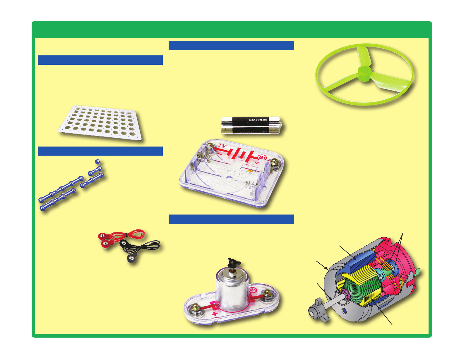
About Your Snap Circuits
®
LIGHT Parts
(Part designs are subject to change without
notice).
BASE GRID
The blue snap wires
are wires used to
connect components.
They are used to
transport electricity and do
not affect circuit performance.
They come in different lengths to
allow orderly arrangement of connections
on the base grid.
The red and black
jumper wires make
exible connections
for times when using
the snap wires would be
difcult. They also are used to
make connections off the base grid.
Wires transport electricity just like pipes are
used to transport water. The colorful plastic
coating protects them and prevents electricity
from getting in or out.
Glow-in-the-dark Fan
Electromagnet
Shaft
Shell
Magnet
Power Contacts
BATTERY HOLDER
How does electricity turn the shaft in the motor?
The answer is magnetism. Electricity is closely
related to magnetism, and an electric current
owing in a wire has a magnetic eld similar to
that of a very, very tiny magnet. Inside the motor
is a coil of wire with many loops wrapped around
metal plates. This is called an electromagnet. If
a large electric current ows through the loops, it
will turn ordinary metal into a magnet. The motor
shell also has a magnet on it. When electricity
ows through the electromagnet, it repels from
the magnet on the motor shell and the shaft
spins. If the fan is on the motor shaft, then its
blades will create airow.
Motor (M1)
The base grid is a platform for mounting parts
and wires. It functions like the printed circuit
boards used in most electronic products, or like
how the walls are used for mounting the electrical
wiring in your home.
SNAP WIRES & JUMPER WIRES
The motor (M1) converts electricity into
mechanical motion. An electric current in the
motor will turn the shaft and the motor blades,
and the fan blade if it is on the motor.
The batteries (B1) produce an electrical
voltage
using a chemical reaction. This “voltage” can
be thought of as electrical pressure, pushing
electricity through a circuit just like a pump
pushes water through pipes. This voltage is much
lower and much safer than that used in your
house wiring. Using more batteries increases
the “pressure”, therefore, more electricity ows.
Battery Holder (B1)
MOTOR
7
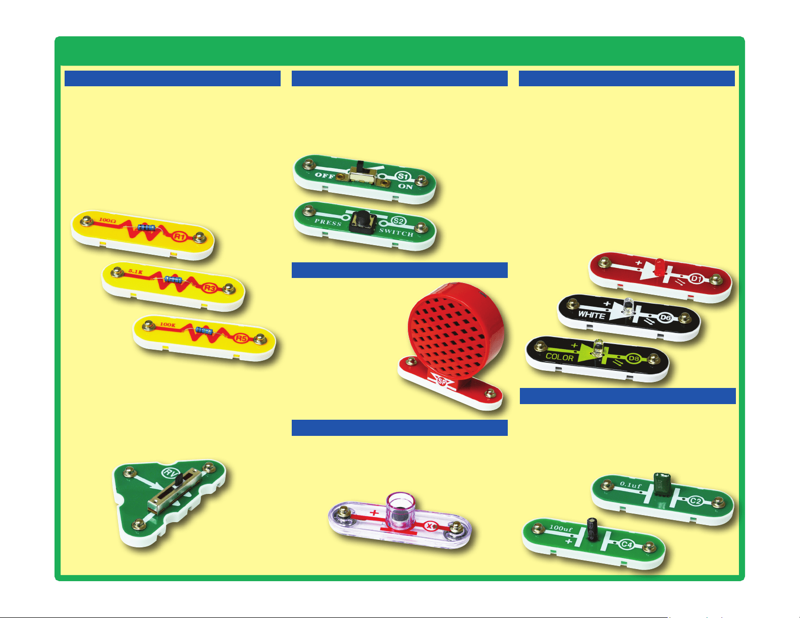
About Your Snap Circuits
®
LIGHT Parts
RESISTORS LEDs
Adjustable Resistor (RV)
Resistors (R1, R3, & R5)
SLIDE & PRESS SWITCHES
The speaker (SP) converts
electricity into sound by
making mechanical vib-
rations. These vibrations
create variations in air
pressure, which travel
across the room. You
“hear” sound when
your ears feel these
air pressure variations.
SPEAKER
Speaker (SP)
The adjustable resistor (RV) is a 50kW resistor
but with a center tap that can be adjusted
between 200W and 50kW.
Resistors “resist” the ow of electricity and are
used to control or limit the current in a circuit.
Snap Circuits
®
LIGHT includes 100W (R1), 5.1kW
(R3), and 100kW (R5) resistors (“k” symbolizes
1,000, so R5 is really 100,000W). Materials like
metal have very low resistance (<1W), while
materials like paper, plastic, and air have near-
innite resistance. Increasing circuit resistance
reduces the ow of electricity.
The slide & press switches (S1 & S2) connect
(pressed or “ON”) or disconnect (not pressed or
“OFF”) the wires in a circuit. When ON they have
no effect on circuit performance. Switches turn on
electricity just like a faucet turns on water from a pipe.
Slide & Press
Switches
(S1 & S2)
LED’s
(D1, D6, & D8)
The red,white,andcolorLED’s(D1,D6,&
D8) are light emitting diodes, and may be
thought of as a special one-way light bulbs. In
the “forward” direction, (indicated by the “arrow”
in the symbol) electricity ows if the voltage
exceeds a turn-on threshold (about 1.5V for red,
about 3.0V for white, and in between for other
colors); brightness then increases. The color
LED contains red, green, and blue LEDs, with a
micro-circuit controlling then. A high current will
burn out an LED, so the current must be limited
by other components in the circuit. LED’s block
electricity in the “reverse” direction.
CAPACITOR
The 0.1mF and 100mF capacitors (C2 & C4) can
store electrical pressure (voltage) for periods of
time. This storage ability allows them to block
stable voltage signals and pass changing ones.
Capacitors are used for filtering and delay
circuits.
Capacitors
(C2 & C4)
Microphone (X1)
The microphone (X1) is actually a resistor that
changes in value when changes in air pressure
(sounds) apply pressure to its surface. Its
resistance typically varies between 1kW and
10kW.
MICROPHONE
8
About Your Snap Circuits
®
LIGHT Parts
TRANSISTORS
The phototransistor (Q4) is a transistor that
uses light to control electric current.
Phototransistor (Q4)
ELECTRONIC MODULES
(+)
NC
OUT
(–)
CTL
Connections:
(+) - power from batteries
(–) - power return to batteries
OUT - output connection
CTL - strobe speed control
NC - not used
See project 31 for example of
proper connections.
Connections:
R - red color control
G - green color control
B - blue color control
(+) - power from batteries
INP - circuit input
FB - feedback connection
(–) - power return to batteries
IN - audio input jack
OUT - audio output jack
See projects 5, 6, 12, and 83 for
examples of proper connections.
The
color organ (U22) contains resistors, capacitors,
transistors, a tri-color LED, and integrated circuits. The
LED in it can change colors by direct control, or in synch
with an audio input signal. A schematic for it is available
at www.elenco.com/faqs/
B
(+)
FB
INP(–)
G
R
OUT
IN
The
strobe IC (U23) contains resistors, capacitors, and
transistors that are needed to make a strobe light circuit.
A schematic for it is available at www.elenco.com/faqs/
Infrared module (U24)
OTHER PARTS
Prismatic film separates light into
different colors. The red, green, & blue
lters lter out colors.
The disc holder and discs produce amazing effects when
used with the Strobe Effects circuit (project 31).
The Infrared module (U24) is a miniaturized
infrared receiver circuit for remote control.
The PNP & NPN transistors (Q1 & Q2) are
components that use a small electric current
to control a large current, and are used in
switching, amplier, and buffering applications.
They are easy to miniaturize, and are the main
building blocks of integrated circuits including
the microprocessor and memory circuits in
computers.
PNP & NPN Transistors (Q1 & Q2)
The LED attachments can be used with
any of the LEDs (red, white, color, and
the color organ) to enhance the light
effects.
The fiber optic cable carries light
between two places. The light can be
encoded to transmit information. The
clear and black holders are used to
attach it to circuits.
Fiber Optic Tree
Light
Tower
Egg
9
Introduction to Electricity
What is electricity? Nobody really knows. We only know how to produce it,
understand its properties, and how to control it. Electricity is the movement of sub-
atomic charged particles (called electrons) through a material due to electrical
pressure across the material, such as from a battery.
Power sources, such as batteries, push electricity through a circuit, like a pump
pushes water through pipes. Wires carry electricity, like pipes carry water. Devices
like LEDs, motors, and speakers use the energy in electricity to do things. Switches
and transistors control the ow of electricity like valves and faucets control water.
Resistors limit the ow of electricity.
The electrical pressure exerted by a battery or other power source is called
voltage and is measured in volts (V). Notice the “+” and “–” signs on the battery;
these indicate which direction the battery will “pump” the electricity.
The electric current is a measure of how fast electricity is owing in a wire, just
as the water current describes how fast water is owing in a pipe. It is expressed
in amperes (A) or milliamps (mA, 1/1000 of an ampere).
The “power” of electricity is a measure of how fast energy is moving through a
wire. It is a combination of the voltage and current (Power = Voltage x Current). It
is expressed in watts (W).
The resistance of a component or circuit represents how much it resists the
electrical pressure (voltage) and limits the ow of electric current. The relationship
is Voltage = Current x Resistance. When the resistance increases, less current
ows. Resistance is measured in ohms (W), or kilo ohms (kW, 1000 ohms).
Nearly all of the electricity used in our world is produced at enormous generators
driven by steam or water pressure. Wires are used to efciently transport this
energy to homes and businesses where it is used. Motors convert the electricity
back into mechanical form to drive machinery and appliances. The most important
aspect of electricity in our society is that it allows energy to be easily transported
over distances.
Note that “distances” includes not just large distances but also tiny distances. Try
to imagine a plumbing structure of the same complexity as the circuitry inside a
portable radio - it would have to be large because we can’t make water pipes so
small. Electricity allows complex designs to be made very small.
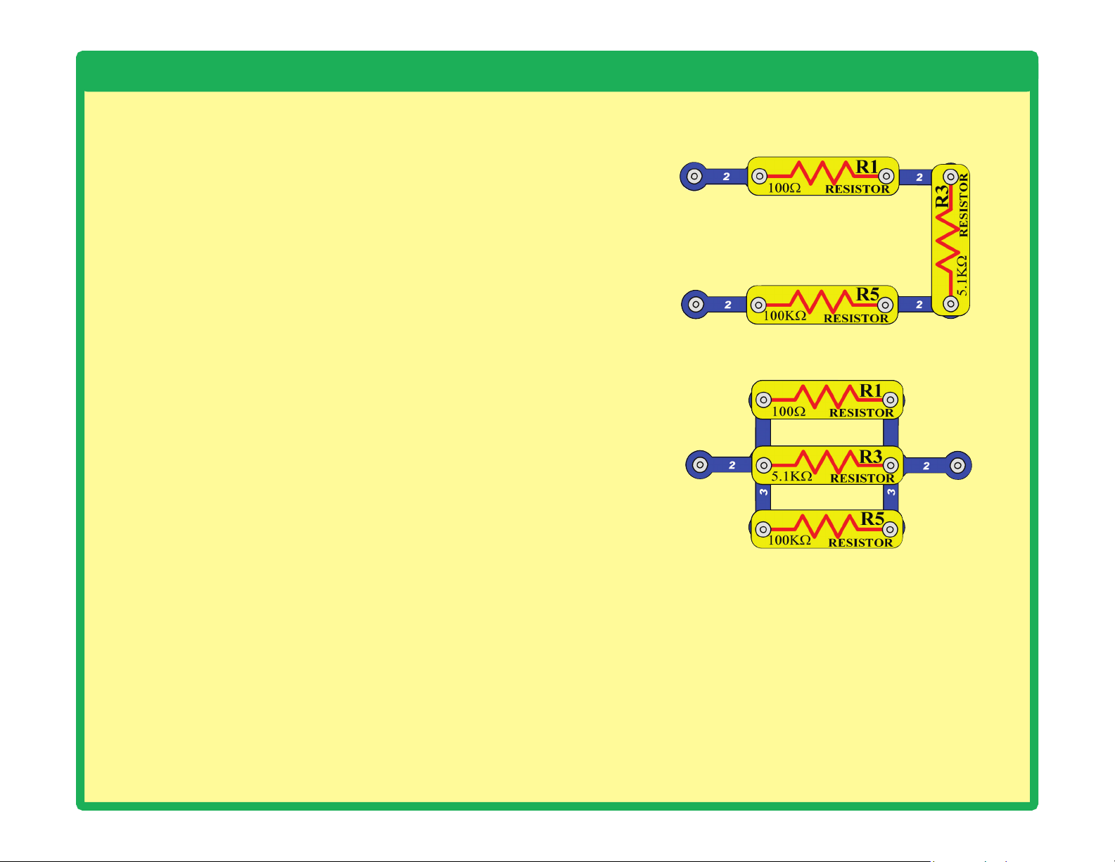
There are two ways of arranging parts in a circuit, in series or
in parallel. Here are examples:
Placing components in series increases the resistance; highest
value dominates. Placing components in parallel decreases
the resistance; lower value dominates.
The parts within these series and parallel sub-circuits may be
arranged in different ways without changing what the circuit
does. Large circuits are made of combinations of smaller
series and parallel circuits.
Series Circuit
Parallel Circuit
10
Light in Our World
What would our world be like without light?
Moving and doing things in total darkness
would be much more difficult, because
everyone would be blind. Plants rely on
sunlight for energy and would die without it.
If all the plants die, then people and animals
would have nothing to eat, and would starve.
Let’s hope we never have to live in a world
without light.
Light is energy, traveling at high speed.
Sunlight can warm up your skin, as can bright
lights in a concert hall or playhouse. Light can
carry information. For example, our brains
analyze the light received in our eyes, to learn
what is around us. In ber optic cables, beams
of light carry data between cities. Infrared light
from a remote control can tell a TV to change
to a different channel.
Light moves as super-tiny charges, which
are so full of energy they go ying off in all
directions.
This happens when a material has too much
energy, and some of the energy changes
form. For example, a light bulb makes light
when an electric current makes the lament
so hot that it glows. Some of the energy in
a burning re escapes by changing to light.
Our bright sun makes so much light because
it is basically a gigantic ball of thermonuclear
reactions. Light emitting diodes (LEDs) make
light by converting excess electrical energy.
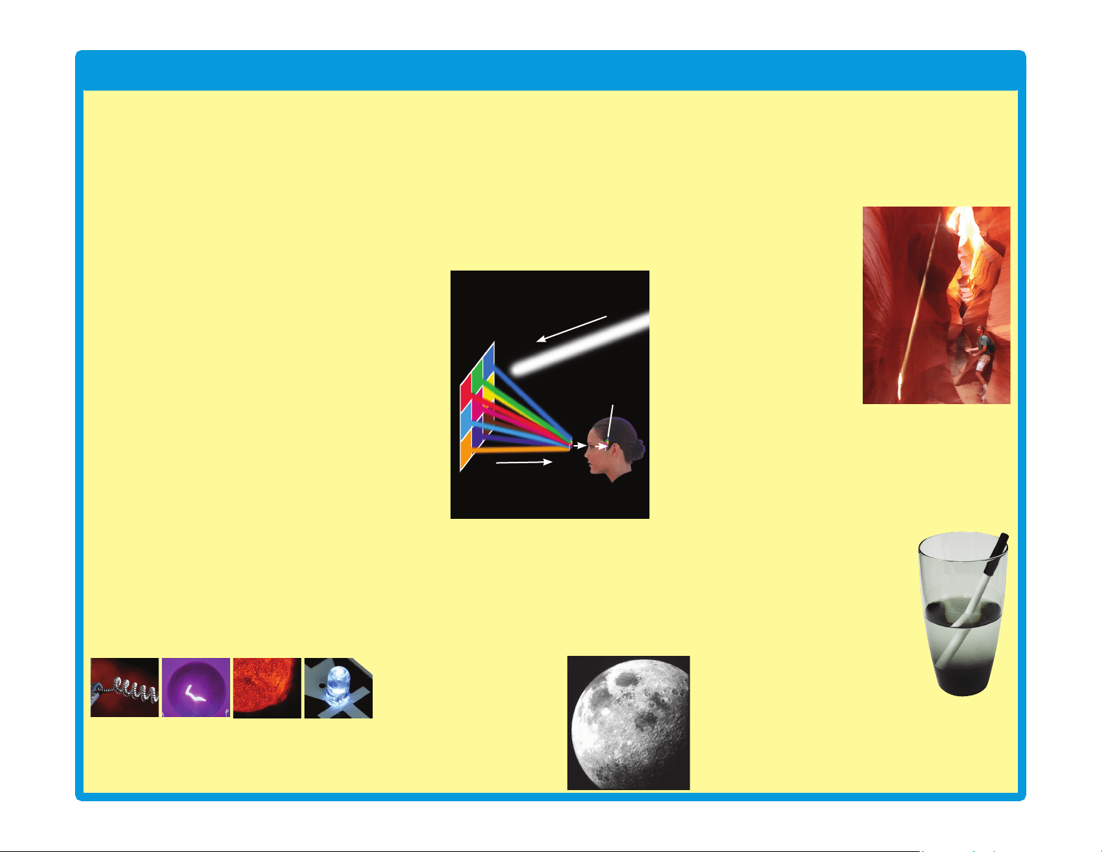
You “see” when light enters your eyes. When
you turn on a light in a room, the light shines
on everything around it. When light shines on
something, some of the light is absorbed into
it, and the rest is reected off. The absorbed
light is converted to heat, and the reected
light is scattered around the room. Some of
the shining and reected light might reach
your eyes. Your brain interprets the light into
your eyes, and makes the mental picture you
see.
When all the light shining on something is
absorbed, with none reected towards your
eyes, then you can’t see it. The object will
appear dark. The brighter an object appears,
the more light was reected off it and into your
eyes. Some materials, like air and clear glass,
let light pass through them.
You can only see the
moon when light from
the sun bounces off it,
and reects to earth.
You can’t see a beam of light traveling across
a room, unless something scatters the light
and some reaches your eyes. In a dusty room,
sometimes you can see the dust particles
oating in the air when sunlight hits them.
In this photograph,
sand has been
tossed into the air,
which is illuminated
by a narrow beam of
sunlight coming down
into the canyon.
When you turn on a
light, you instantly
see everything. This
happens because
light is very fast, and
travels about 186,000
miles a second in air.
Light rays can bend when they pass between
different materials, such as air and water.
Light bends because its speed changes. The
speed of light in water is only about 125,000
miles a second.
The part of the pen in water
looks distorted, because light
changes speed when entering
and leaving the water.
When you look directly out a
glass window, you can see
clearly through it. When you
look through the window at
a wide angle, you can see
through it, but also see a
reection in it. When you try to look through
the window at a really wide angle, you can’t
see through it at all, and only see reections.
Try looking through a window in your home at
really wide angles.
Light bulb
lament
Glowing
light bulb
lament
Close-up
view of the
Sun
Glowing
white LED
(D6)
White light beam
Reected light
Mental picture
11
Light in Our World
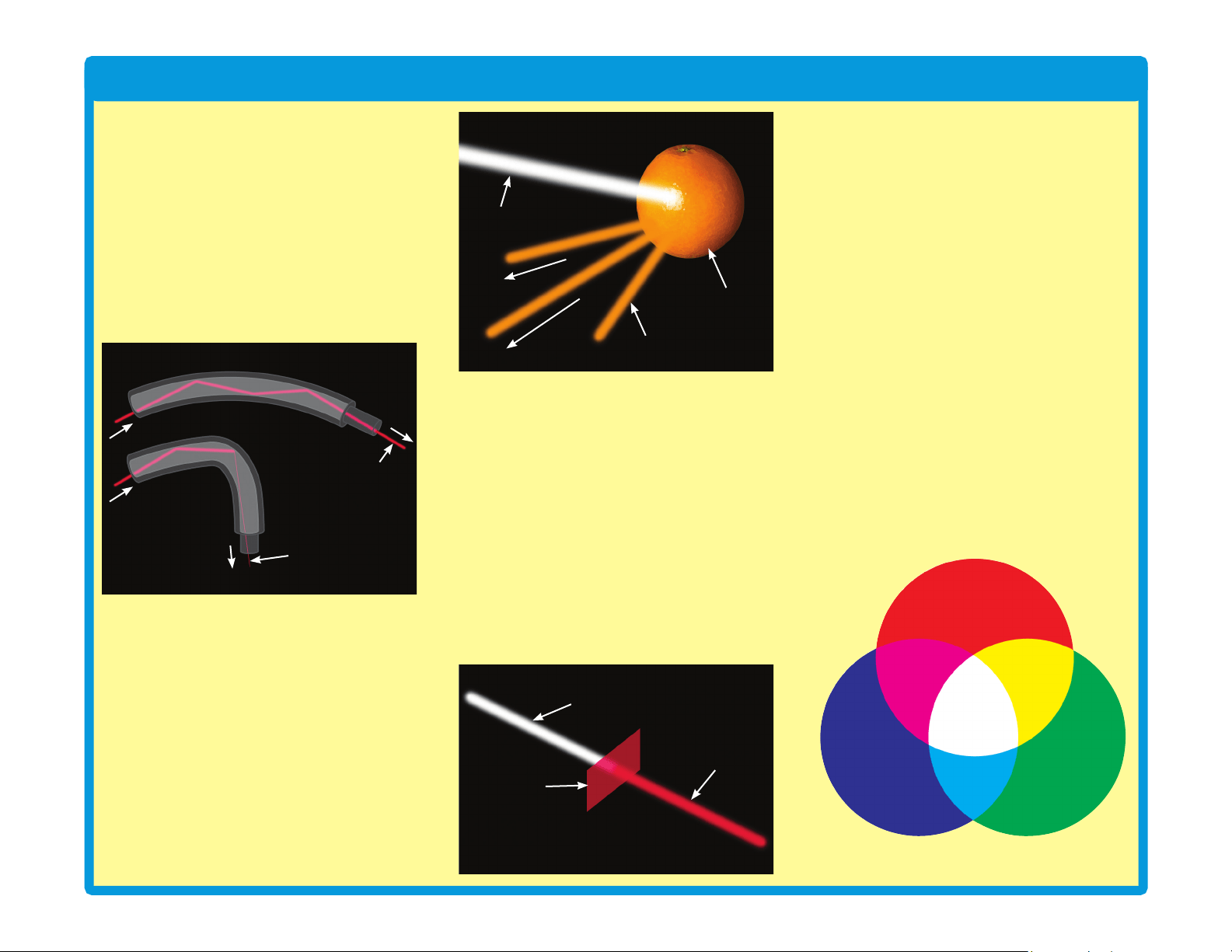
When light hits a glass surface at a wide
enough angle, all the light is reected. Fiber
optic cables have arrays of exible glass bers.
In these cables, light rays move through by
bouncing along the inside walls at wide angles,
and can travel great distances. Light moves
through the cable even if it is bent a little, but if
there is a tight bend then most of the light will
be absorbed instead of reected forward.
Translucent materials, such as the tower and
egg LED attachments in this set, allow some
light to pass through but scatter it around.
Color
The things around you have different colors
because they reflect the colors that you
see, while absorbing the other colors. Light
produced by the sun or a light bulb is called
white light. White light is not really a color
itself, but is a mixture of all the colors seen in
a rainbow.
White light shines on an orange. All colors in
the light are absorbed except orange, which
is reected off. The reected orange light
reaches our eyes, so we see it as having
orange color.
White light can be split up into its different
colors. This happens when light passes
between different materials, and the different
colors in it are bent by different amounts. You
can see this by viewing white light through
prismatic film, as you do in project 51.
Sometimes water in the air can bend sunlight
by just the right amounts, and make a rainbow.
Color lters allow one color to pass through,
and absorb the other colors. When you look
through a red lter, everything looks red (or
black, if there isn’t any red in what you are
looking at). This set includes red, green, and
blue lters, so try looking through them.
Any color of light can be made, by mixing
different amounts of red, green, and blue
light. Mixing equal amounts of these colors
produces white light. If you look at a TV
screen with a magnifying glass, you will see
it actually consists of tiny red, green, and blue
lights, using different intensities to make all
the colors.
This set includes several LEDs (D1, D6, D8,
and in U22) with different colors. The color
emitted by an LED depends on the material
used in it. LEDs are more energy-efcient
than incandescent light bulbs, can be made
smaller, and last longer.
The LED in the color organ module (U22)
contains separate red, green, and blue LEDs.
The color organ can combine these colors
to make yellow, cyan, purple, and white, as
shown in project 6. The color organ does
not allow you to adjust the amount of each
color. In project 34, several colors are mixed
together on a spinning disc.
Red
Green
YellowMagenta
Blue
Cyan
White
Orange
Orange reected light
White light beam
White light beam
Red lter
Red light beam
Cable slightly bent
Cable with
tight bend
Light beam
(full strength)
Weak light beam
12
Light in Our World
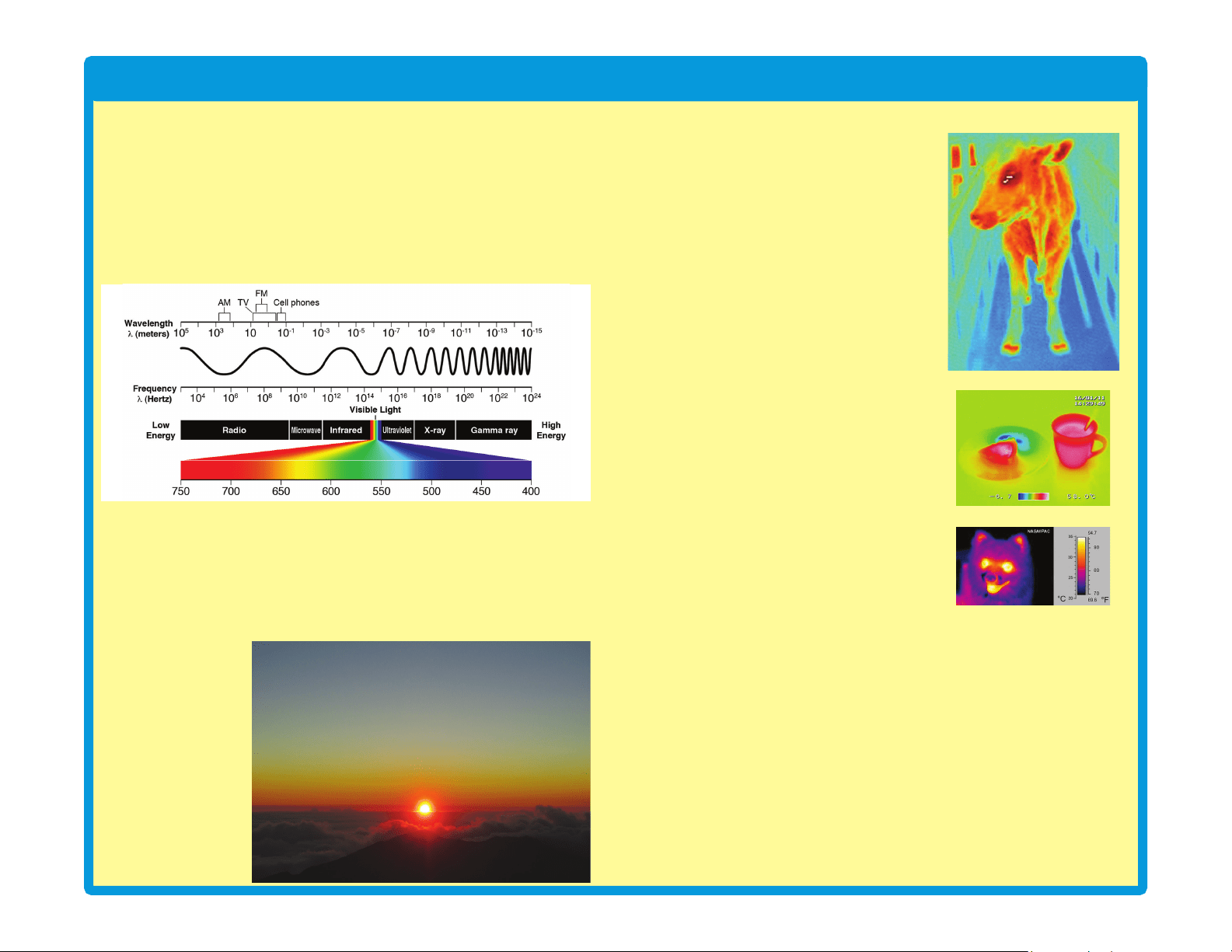
The Spectrum of Light
The light our eyes see is only part of what is around us. Visible light, infrared
light, radio waves (including TV broadcasting and cell phones), microwaves,
and x-rays are all forms of electromagnetic radiation. They are actually
changing electric and magnetic elds. This radiation travels like waves in
water, spreading out from where it was created. These waves all travel at the
speed of light, but some are longer (higher wavelength) and some repeat faster
(higher frequency). Together they are called the electromagnetic spectrum:
The visible colors (red, orange, yellow, green, blue, and violet) have different
wavelengths. In the right conditions white light from the sun can be separated
according to wavelength, producing a rainbow of color. This happens with an
actual rainbow, and with prismatic lm.
Why is the sky blue? Some sunlight is scattered by tiny particles in the earth’s
atmosphere. The shorter wavelength blue light is scattered more than the
other colors, so the sky appears blue. At sunrise or sunset, longer wavelength
colors like red or
yellow are more
visible in the sky,
because sunlight
passes through more
of the atmosphere
before reaching your
eyes. In space, the
sky always appears
black because there
is no atmosphere or
scattering effect.
Infrared
Infrared light is invisible light given off by
anything warm. Infrared is used in remote
controls to control TVs and appliances.
Infrared is invisible, so it doesn’t disrupt
your view of the TV. Infrared doesn’t go
through walls, so it doesn’t interfere with
devices in other rooms.
The remote control sends a stream of
infrared light pulses to the TV, encoded
with the desired commands. The infrared
light is created using an infrared light
emitting diode (LED). Infrared detectors
convert the received light to electric current,
and decode the commands. The detectors
are tuned to focus on the infrared light,
and ignore visible light. This set contains
an infrared detector (U24), which can
be activated by a TV remote control; see
projects 18 and 25 for examples.
Infrared has other uses such as night vision
devices help to see people and animals in
the dark, by looking at the heat they give
off as infrared light. You probably saw this
in the movies.
Glow-in-the-dark
Some materials can absorb light, store it for a while, and slowly release
it back out. “Glow-in-the-dark” materials can be “charged” by bright light,
then will slowly emit light and “glow” for a while in a dark room. The glow
fan blade in this set has a glow powder mixed in the plastic.
It’s like a slow, delayed reection of the light.
Sound
Sound, like light, spreads out like waves from where it was made. Sound
is variations in air pressure. You “hear” sound when your ears feel these
air pressure variations. Sound has much longer wavelength than light,
which enables sound to travel around corners. Sound can also be
thought of as a wave of vibration, and can travel through water and solid
objects. Sound travels about 1,000 feet per second in air, and about
5,000 feet per second in water.
13
DO’sandDON’TsofBuildingCircuits
After building the circuits given in this booklet, you may wish to experiment on your
own. Use the projects in this booklet as a guide, as many important design concepts
are introduced throughout them. Every circuit will include a power source (the batteries),
a resistance (which might be a resistor, capacitor, motor, integrated circuit, etc.), and
wiring paths between them and back. You must be careful not to create “short circuits”
(very low-resistance paths across the batteries, see examples at right) as this will damage
components and/or quickly drain your batteries. Only connect the color organ (U22), strobe
IC (U23) and infrared module (U24) using congurations given in the projects, incorrectly
doing so may damage them. ELENCO
®
is not responsible for parts damaged due to
incorrect wiring.
Here are some important guidelines:
ALWAYS USE EYE PROTECTION WHEN EXPERIMENTING ON YOUR OWN.
ALWAYS include at least one component that will limit the current through a circuit, such
as the speaker, capacitors, ICs (which must be connected properly), motor,
microphone, phototransistor, or resistors.
ALWAYS use LEDs, transistors, and switches in conjunction with other components that
will limit the current through them. Failure to do so will create a short circuit
and/or damage those parts.
ALWAYS connect capacitors so that the “+” side gets the higher voltage.
ALWAYS disconnect your batteries immediately and check your wiring if something
appears to be getting hot.
ALWAYS check your wiring before turning on a circuit.
ALWAYS connect the color organ (U22), strobe IC (U23) and infrared module (U24)
using congurations given in the projects or as per the connection description
on page 8.
NEVER connect to an electrical outlet in your home in any way.
NEVER leave a circuit unattended when it is turned on.
NEVER touch the motor when it is spinning at high speed.
For all of the projects given in this book, the parts may be arranged in different ways
without changing the circuit. For example, the order of parts connected in series or in
parallel does not matter — what matters is how combinations of these sub-circuits are
arranged together.
Placing a 3-snap wire directly
across the batteries is a
SHORT CIRCUIT.
This is also a
SHORT CIRCUIT.
When the slide switch (S1) is turned on, this large circuit has a SHORT
CIRCUIT path (as shown by the arrows). The short circuit prevents any
other portions of the circuit from ever working.
NEVER
DO!
NEVER
DO!
NEVER
DO!
NEVER
DO!
Examples of SHORT CIRCUITS - NEVER DO THESE!!!
Warning to Snap Circuits
®
owners: Do not use
parts from other Snap Circuits
®
sets with this kit.
Other sets use higher voltage which could damage
parts.
WARNING: SHOCK HAZARD
- Never connect Snap Circuits
®
to the electrical outlets in your home in any way!
!
↯
!
!
! !
You are encouraged to tell us about new circuits you create. If they are
unique, we will post them with your name and state on our website at
www.elenco.com/showcase.
Send your suggestions (with photos) to [email protected].
Elenco
®
provides a circuit designer so that you can make your own
Snap Circuits
®
drawings. This Microsoft
®
Word document can be
downloaded from www.elenco.com/for-makers.
14
Advanced Troubleshooting (Adult supervision recommended)
ELENCO
®
is not responsible for parts
damaged due to incorrect wiring.
If you suspect you have damaged parts, you
can follow this procedure to systematically
determine which ones need replacing:
(Note: Some of these tests connect an LED directly
across the batteries without another component to
limit the current. Normally this might damage the
LED, however Snap Circuits
®
LEDs have internal
resistors added to protect them from incorrect
wiring, and will not be damaged.)
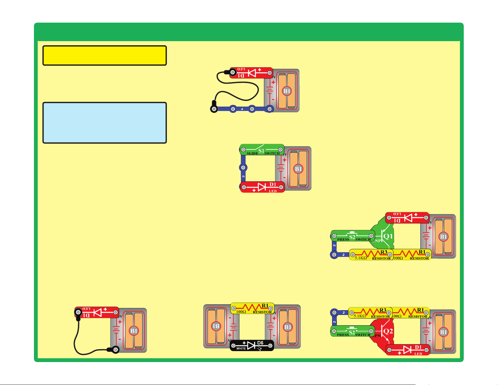
1. Red LED (D1), motor (M1), speaker (SP),
and battery holder (B1): Place batteries
in holder. Place the red LED directly across
the battery holder (LED + to battery +), it
should light. Do the same for the motor, it
should spin. “Tap” the speaker across the
battery holder contacts, you should hear
static as it touches. If none work, then
replace your batteries and repeat. If still
bad, then the battery holder is damaged.
If the motor spins but does not balance the
fan, check the black plastic piece with three
prongs on the motor shaft, and replace it if
it is damaged (this kit includes a spare). To
replace, pry the broken one off the motor
shaft using a screwdriver, then push the
new one on.
2. Red & black jumper wires: Use this mini-
circuit to test each jumper wire, the LED
should light.
3. Snap wires: Use this mini-circuit to test
each of the snap wires, one at a time. The
LED should light.
4. Slide switch (S1) and Press switch (S2):
Use this mini-circuit; if the LED doesn’t light
then the slide switch is bad. Replace the
slide switch
with the press
switch to test it.
5. 100W(R1) and 5.1kW(R3) resistors: Use
the mini-circuit from test 4 but replace the
switch with the 100W resistor (R1); the LED
will be bright if the resistor is good. Next
use the 5.1kW resistor in place of the 100W
resistor; the LED should be much dimmer
but still light.
6. White LED (D6) and color LED (D8): Use
this mini circuit; if the white LED doesn’t light
then D6 is bad. Replace the white LED with
the color LED; it should change colors in a
repetitive pattern, otherwise D8 is bad.
7. Microphone (X1) and
Phototransistor (Q4): Use the mini-circuit
from test 6 but replace the 100W resistor
with the microphone (+ on right); if blowing
into the microphone does not change the
LED brightness then X1 is bad. Replace
the microphone with the phototransistor
(+ on right). Waving your hand over the
phototransistor (changing the light that
shines on it) should change the brightness
of the LED or Q4 is bad.
8. Adjustable resistor (RV): Build project 81,
but use the red LED (D1) in place of the
color LED (D8). Move the resistor control
lever to both sides. When set to each side,
one LED should be bright and the other off
(or very dim); otherwise RV is bad.
9. PNP transistor (Q1): Build the mini-circuit
shown here. The red LED (D1) should only
be on if the press switch (S2) is pressed. If
otherwise, then Q1 is damaged.
10. NPN transistor (Q2): Build the mini-
circuit shown here. The red LED (D1)
should only be on if the press switch
(S2) is pressed. If otherwise, then Q2 is
damaged.
15
Advanced Troubleshooting (Adult supervision recommended)
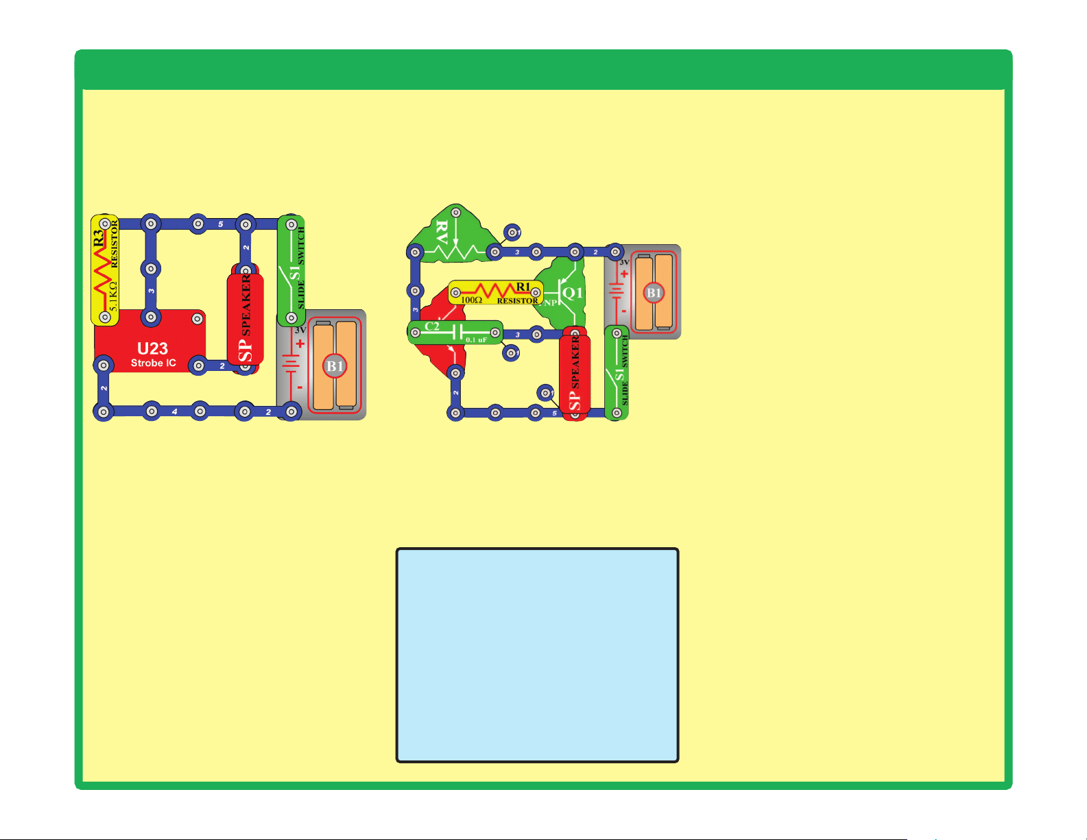
11. Strobe IC (U23) and 100kW resistor
(R5): Build the mini-circuit shown here,
and turn on the switch (S1). The speaker
should make a buzzing sound or U23 is
bad. Next use the 100kW resistor in place
of the 5.1kW resistor; the sound should be
a beeping sound now or R5 is bad.
12. Infrared module (U24): Build project
18, the remote control should turn the red
LED (D1) on; otherwise U24 is bad.
13. 0.1mF capacitor (C2) and 100mF
capacitor (C4): Build this circuit. There
should be a buzzing sound, or C2 is bad.
Next, replace C2 with C4; now you should
hear beeps every 5 seconds, or C4 is bad.
The setting on RV does not matter.
15. Color organ (U22): Do project 83. If parts
A or B do not work, U22 is damaged.
ELENCO
®
150 Carpenter Avenue
Wheeling, IL 60090 U.S.A.
Phone: (847) 541-3800
Fax: (847) 520-0085
e-mail: [email protected]
Website: www.elenco.com
You may order additional /
replacement parts at: www.
elenco.com/replacement-parts/
1
1
1
1
1
1
2
2
2
2
2
2
2
2
3
3
3
1
1
1
1
1
2
2
2
2
2
2
2
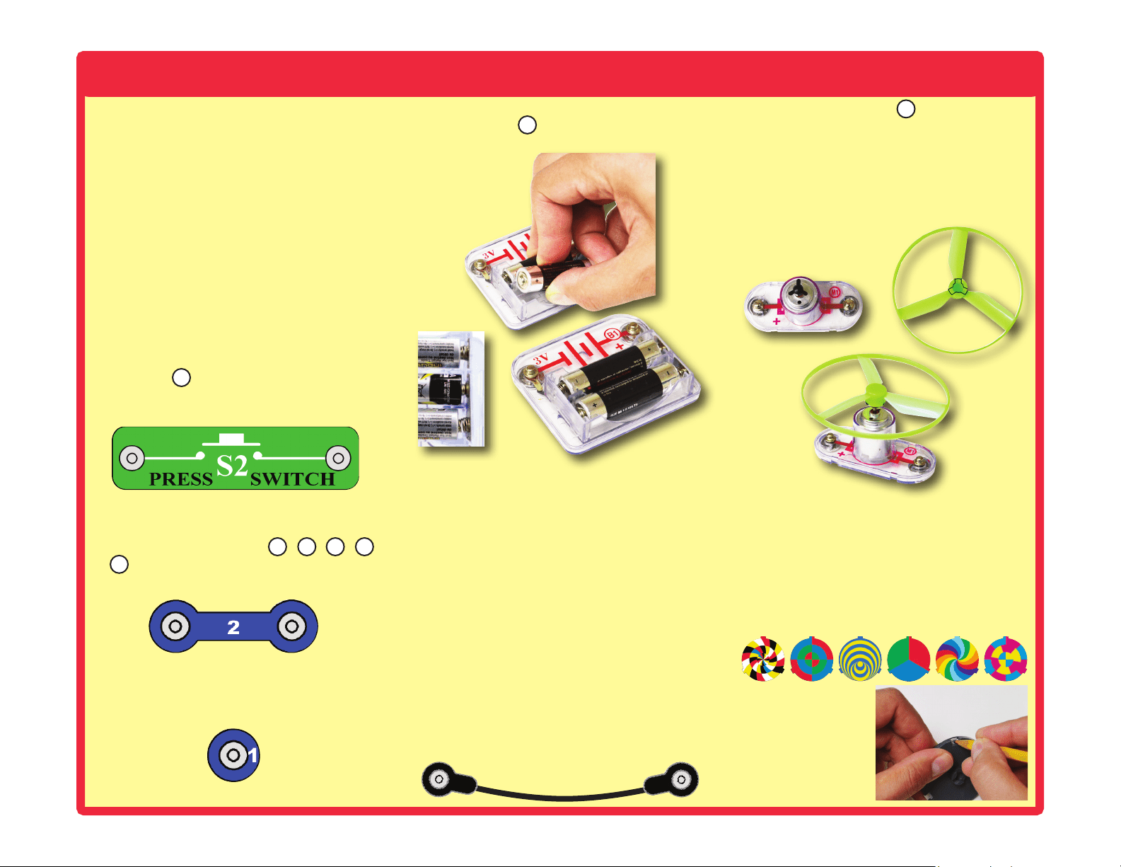
16
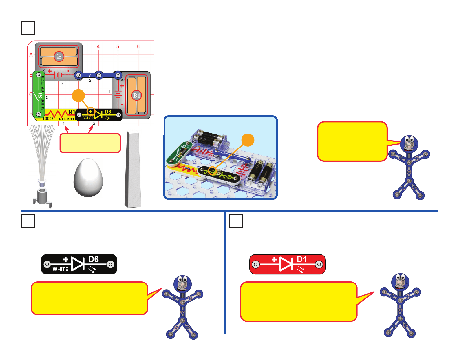
Project 1
Color Light
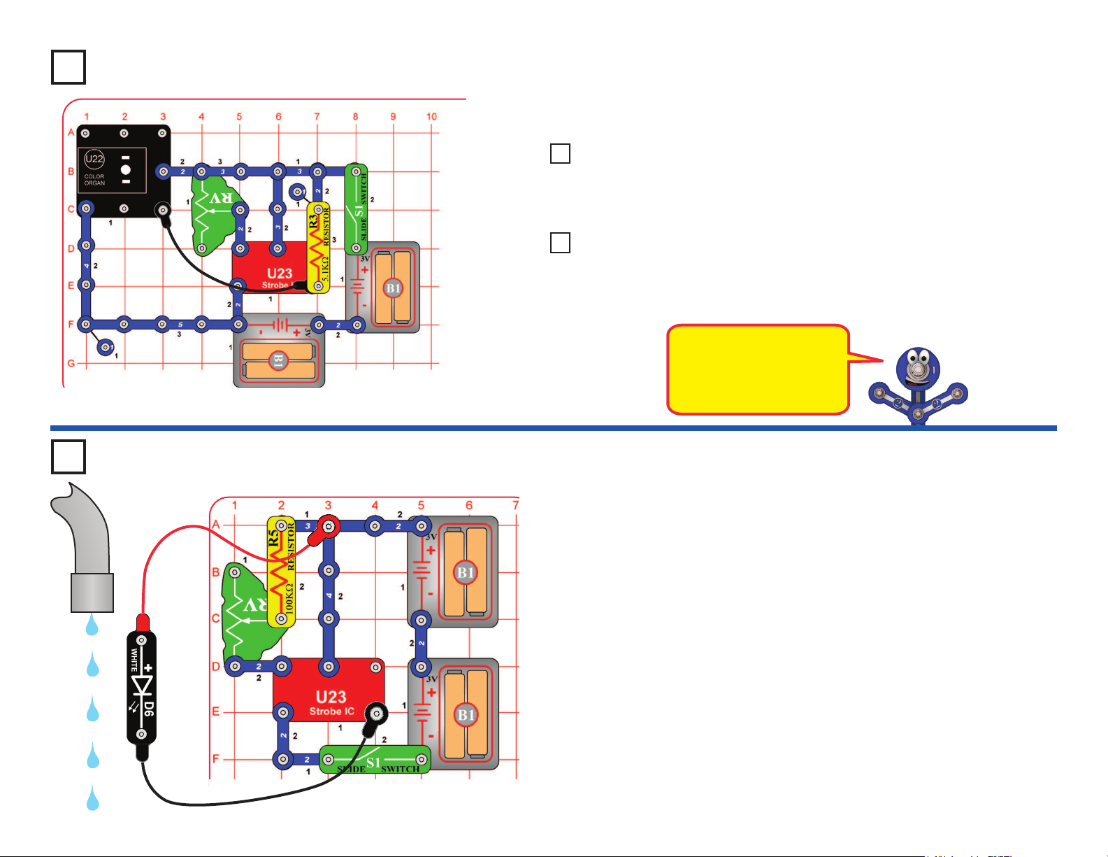
Build the circuit shown on the left by placing all the parts with a black 1 next
to them on the board rst. Then, assemble parts marked with a 2. Install two
(2) “AA” batteries (not included) into each of the battery holders (B1) if you
have not done so already. When installing a battery, be sure the spring
is compressed straight back, and not bent up, down, or to one side.
Battery installation should be supervised by an adult.
Turn on the slide switch (S1), and enjoy the light show from the color
LED (D8). For best effects, place one of the LED attachments (tower, egg,
or ber optic tree) on the color LED, and dim the room lights. The ber optic
tree must be used with its mounting base.
+
Use the circuit built in project 1,
but replace the color LED (D8)
with the white LED (D6). Try it
with one of the LED attachments,
and in a dark room.
Use the circuit built in project 2,
but replace the white LED (D6)
with the red LED (D1). Try it with
one of the LED attachments,
and in a dark room.
Project 2 White Light Project 3 Red Light
+
The white LED produces very bright light.
LEDs are this one are increasingly being
used for home lighting and ashlights. They
are more efcient than normal light bulbs.
The red LED is not nearly as bright as the
other LEDs. LEDs like this one are used
as indicators in many products in your
home. They are inexpensive, but don’t
produce much light.
Placement Level
Numbers
Snappy says the color
LED actually contains
separate red, green, and
blue lights, with a micro-
circuit controlling them.
LED Attachments
17
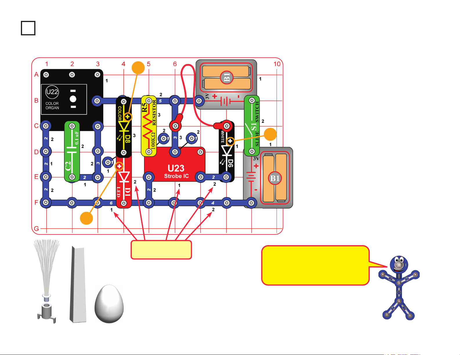
Snap Circuits
®
uses electronic blocks that snap onto
a clear plastic grid to build different circuits. These
blocks have different colors and numbers on them so
that you can easily identify them.
Build the circuit shown above by placing all the parts
with a black 1 next to them on the board rst. Then,
assemble parts marked with a 2.
If desired, place any of the LED attachments (tower,
egg, or ber optic tree) on any of the LEDs (red (D1),
color (D8), white (D6), or the LED on the color organ
IC (U22). Note that the ber optic tree requires its
mounting base.
Turn on slide switch (S1) and enjoy the show!
Project 4
Light Show
+
+
+
Placement Level
Numbers
LED Attachments
All the lights in this set are LEDs - Light
Emitting Diodes. LEDs convert electrical
energy into light; the color of the light
emitted depends on the characteristics
of the material used in them.
18
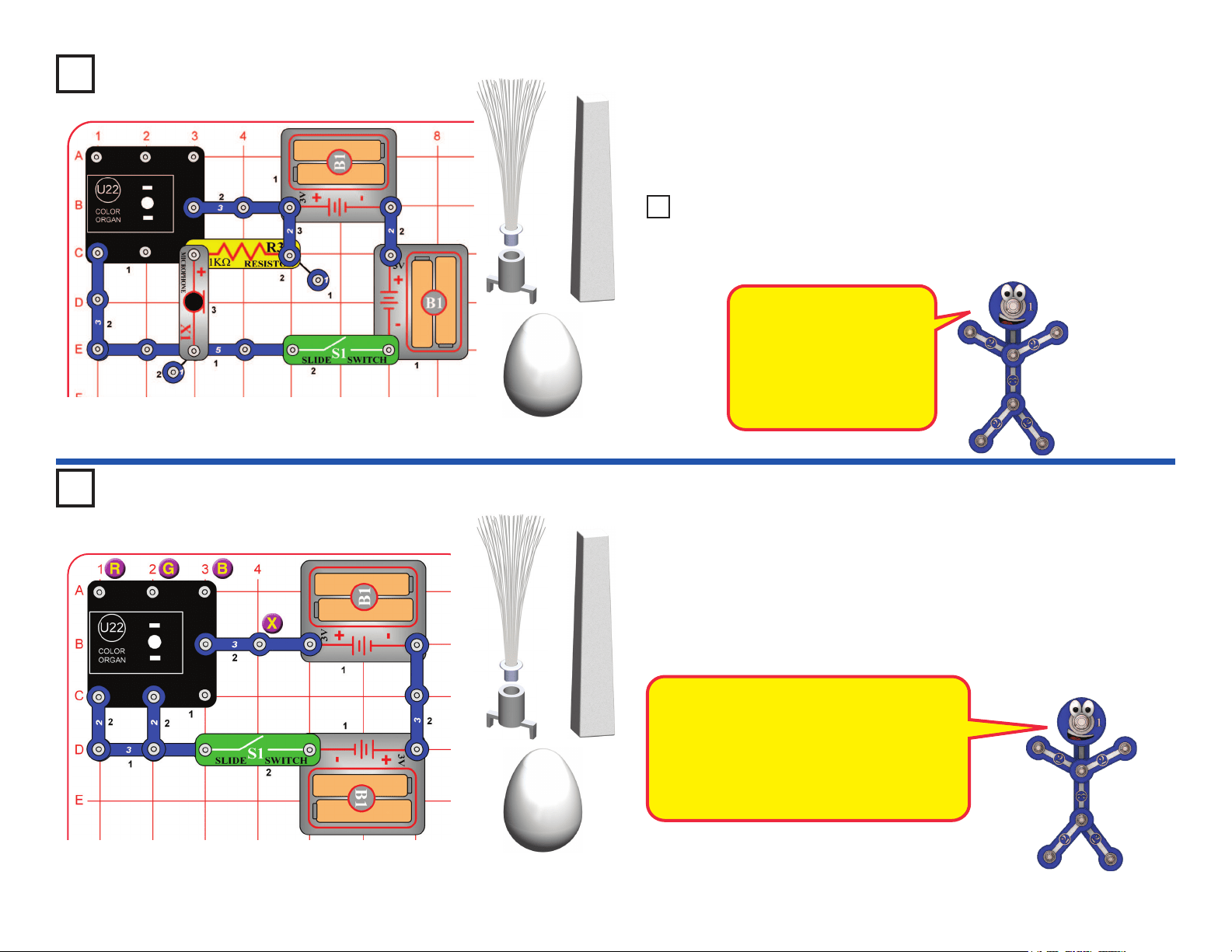
Project 5
Voice Light Show
Project 6 Play the Color Organ
Build the circuit as shown, and place one of the LED attachments (tower,
egg, or ber optic tree) over the LED on the color organ (U22). Turn on
the switch (S1) and talk. The color organ light will follow your voice, in
tone and loudness.
Build the circuit as shown, and turn on the switch (S1). Place one of the
LED attachments on the color organ (U22). Wet your ngers, and touch
them between the point marked “X”, and points marked “R”, “G”, or “B” in
the drawing. Try X with every combination of R, G, and B, including touching
them all at the same time.
The light in the color organ module is
actually red, green, and blue LEDs together.
The points marked R, G, and B control the
light for those colors. Combining red and
green makes yellow, green and blue makes
cyan, red and blue makes purple, and
combining all three colors makes white.
How does it work? The
microphone converts your
voice to an electrical signal,
which controls an electronic
counter in the color organ.
The counter controls a red-
green-blue LED.
LED Attachments
LED Attachments
Replace the microphone (X1) with the phototransistor (“+” on top) and
vary the amount of light shining on it. The light on the color organ is
changing only if there is enough light on the phototransistor.
Project NEW1 Light Changer
19
This circuit will make the fan spin faster and y higher than the preceding
circuit, making it easy to lose your fan.
WARNING: Elenco
®
Electronics Inc. is not responsible for lost or
broken fans! You may purchase replacement fans at www. snapcircuits.net.
Push the press switch (S2) until the motor reaches full speed, then release
it. The fan blade should rise and oat through the air like a ying saucer. Be
careful not to look directly down on fan blade when it is spinning.
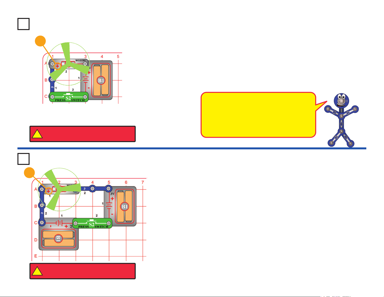
Project 7
Flying Saucer
Project 8 Super Flying Saucer
Push the press switch (S2) until the motor reaches full speed, then release
it. The fan blade should rise and oat through the air like a ying saucer. Be
careful not to look directly down on fan blade when it is spinning.
If the fan doesn’t y off, then press the switch several times rapidly when it is
at full speed. The motor spins faster when the batteries are new.
The glow fan will glow in the dark. It will glow best after absorbing sunlight
for a while. The glow fan is made of plastic, so be careful not to let it get hot
enough to melt. The glow looks best in a dimly lit room.
+
The air is being blown down through the blade and
the motor rotation locks the fan on the shaft. When
the motor is turned off, the blade unlocks from
the shaft and is free to act as a propeller and y
through the air. If speed of rotation is too slow, the
fan will remain on the motor shaft because it does
not have enough lift to propel it.
+
!
WARNING: Moving parts. Do not touch the fan or
motor during operation. Do not lean over the motor.
!
WARNING: Moving parts. Do not touch the fan or
motor during operation. Do not lean over the motor.
20
Project 9
Super Voice Light Show
This circuit is similar to project 5, but more sensitive. Build the circuit as
shown, initially set the adjustable resisitor (RV) to the middle, and place one
of the LED attachments (tower, egg, or ber optic tree) over the LED on
the color organ (U22). Turn on the switch (S1) and talk, or place a device
playing music near the micorphone (X1). The color organ light will follow the
sound, in tone and loudness.The speaker (SP) is used here to regulate a
transistor amplier for the microphone, and will not make sound.
Project 12
Color Oscillator
Build the circuit as shown, and place one of the LED attachments (tower,
egg, or ber optic tree) over the LED on the Color Organ (U22). Turn on the
switch (S1) and watch. The color organ light will change colors on its own.
This circuit is an oscillator;
it uses the color organ to
control itself.
LED
Attachments
Replace the 3-snap wire that is across base grid locations C2-E2 (next
to the 0.1mF capacitor (C2)) with the 100kW resistor (R5). Now the
color organ light changes more slowly.
Project 13 Slower Oscillator
Replace the microphone (X1) with the motor (M1). Spin the motor top
with your ngers to change the color organ light.
Project 10 Finger Light Show
Replace the motor with the color LED (D8) to create some interesting
effects.
Project 11 Funky Show
LED Attachments

21
Project 14
Sound Maker
Build the circuit and turn on the switch (S1). You hear sound from the speaker.
Adjust the sound using the lever on the adjustable resistor (RV), and by
pushing the press switch (S2).
Note: In rare cases the circuit may not work at all settings on RV. If this
happens, move the RV lever to the side near the strobe IC, turn the slide switch
off and on to reset the circuit, and only move the RV lever over a small range.
The strobe IC (U23) produces an electrical “tone”. The
pitch of the “tone” is adjusted by changing how much
electricity ows into its upper-left snap, using a resistor.
The electrical tone it produces can be used to make sound
using a speaker, or to control the ash rate of an LED.
The color LED will not be changing colors like it does in
other circuits. When the strobe IC (U23) turns the color
LED on and off, it resets the color-control microcircuit in the
color LED. Even your slowest strobe speed is too fast for
the color LED.
Use the preceding circuit, but replace the speaker with the white
LED (D6). Now you have a strobe light! When S2 is pressed, the light may
be blinking so fast that it appears to be on continuously.
Use the preceding circuit, but replace the white LED with the color LED (D8).
Use the preceding circuit but replace the color LED (D8) with the red
LED (D1).
Project 15 Strobe Light
Project 16 Color Strobe Light
Project 17 Red Light Strobe
Project 18 Infrared Detector
You need an infrared remote control for this project, such as any TV/stereo/
DVD remote control in your home.
Build the circuit and turn on the switch (S1). Point your remote control toward
the infrared module (U24) and press any button to activate the red LED (D1).
Sometimes this circuit may activate without a remote control, due to infrared
in sunlight or some room lights. If this happens, try moving to a dark room.
TV remote controls transmit a sequence of
pulses representing the TV model and the
button that was pressed. The U24 infrared
detector is just looking any infrared signal.
Remote

22
Build the circuit as shown. Place the clear cable holder on the red LED (D1)
and the black cable holder on the phototransistor (Q4), then place the ber
optic cable into the holders as far as it will go. For best performance the
cable should stand straight up in the holders, without bending them.
Turn on slide switch (S1) and move the lever on the adjustable resistor (RV)
around. The sound from the speaker (SP) changes as you move the lever
on RV.
Project 19 Blinking Colors
Build the circuit as shown and turn on the slide switch (S1). The white and
color LEDs (D6 & D8) are blinking.
Push the press switch (S2). Now the red LED (D1) is blinking but the white
LED is much dimmer or off.
If you swap the locations of the red and white LEDs, then the red LED will
be blinking and the white LED will be off, and pushing the press switch may
dimly light the white LED but the red LED will hardly be affected.
Red light is easier for LEDs to produce than
white light. When the red and white LEDs are
connected in parallel (which happens when
S2 is pressed), the red LED will dominate
because it turns on more easily.
Fiber Optics
Project 20
Black
Clear
This project is more exciting than it looks. The tone sounds
produced by the strobe IC (U23) are played on the speaker (SP),
even though there is no electrical connection between them.
The left half the circuit makes a coded light signal, which you see
in the red LED (D1). The right half of the circuit decodes the light
signal and plays it on the speaker. The ber optic cable is used
to transmit the light signal between the two sides of the circuit.
There is no electrical connection between the left and right halves
of the circuit, only a light connection using ber optics! If your ber
optic cable was longer, the two halves of the circuit could be many
miles apart.
This circuit is an example of using ber optic cables for
communication. Fiber optics allows information to be transmitted
across great distances at very high speeds with very low
distortion, by using light.
23
Build the circuit as shown. Place either the glow fan
or the light fan on the motor (M1) shaft, so that it is
stable on the little black piece. Place the clear ber
optic holder on the color LED (D8) and the black ber
optic holder on the phototransistor (Q4), then insert
the ber optic cable between them, but don’t let it lay
close to the fan on the motor. For best performance
the ber optic cable should stand straight up in the
holders, without bending them. For best effects, place
one of the LED attachments over the light on the
color organ.
Turn on slide switch (S1). Talk into the microphone
(X1) and adjust the lever on the adjustable resistor
(RV) for best sound and light effects.
Push the press switch (S2) until the motor reaches
full speed, then release it. The fan will rise into the air
like a ying saucer.
“Playing the Color Organ”: Wet your ngers, and
touch them between the point marked “X”, and “R”,
“G”, or “B” in the drawing.
Project 21
Big Circuit
+
This circuit does a lot of
different things at once.
LED Attachments
Black
Clear
1
1
!
WARNING: Moving parts. Do not touch the fan or
motor during operation. Do not lean over the motor.
24
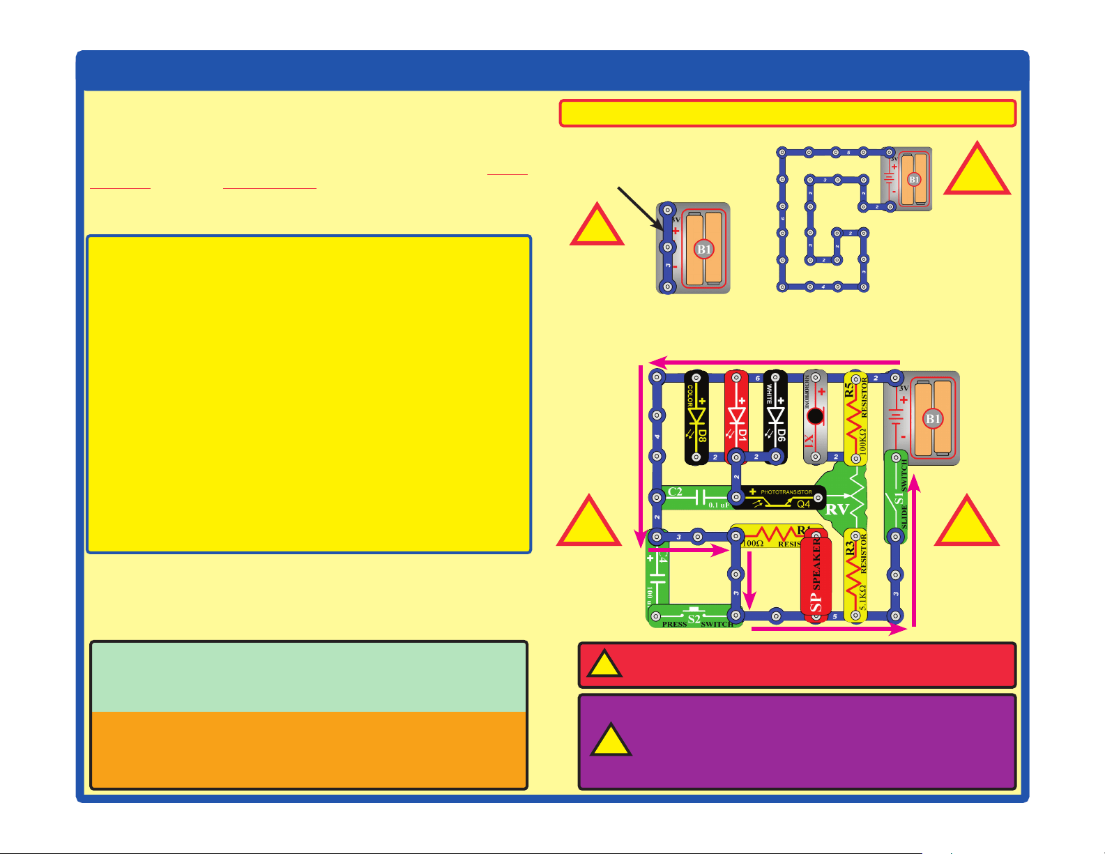
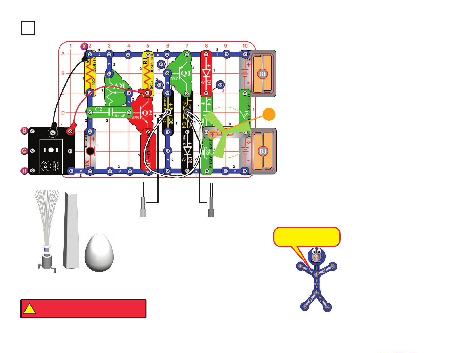
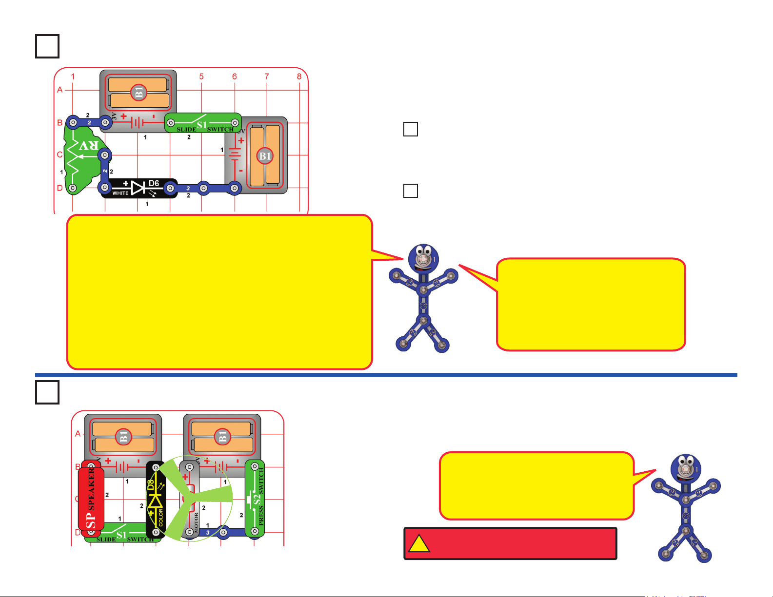
Build the circuit as shown. Place the glow fan on the motor
(M1) shaft, so that it is stable on the little black piece. Place
the clear ber optic holder on the white LED (D6). and the
black ber optic holder on the phototransistor (Q4), then
insert the ber optic cable between them, but don’t let it
lay close to the fan on the motor. For best performance the
ber optic cable should stand straight up in the holders,
without bending them. For best effects, place one of the
LED attachments over the light on the color organ, and one
on the color LED (D8).
Optional: connect a music device to the color organ (U22)
as shown, and start music on it (the color organ light will
change to the music, but you will not hear it unless you also
connect headphones).
Turn on slide switch (S1). A tone is heard from the speaker
(SP), and all the lights (D1, D6, D8, and on U22) are on.
Push the press switch (S2) until the motor reaches full
speed, then release it. The fan will rise into the air like a
ying saucer. Be careful not to look down on the fan when it
is spinning.
This circuit also works if you move the clear ber optic
holder from the white LED (D6) to the color LED (D8).
Project 22 Super Circuit
Headphones
(optional)
Music device
(optional)
+
Black
Clear
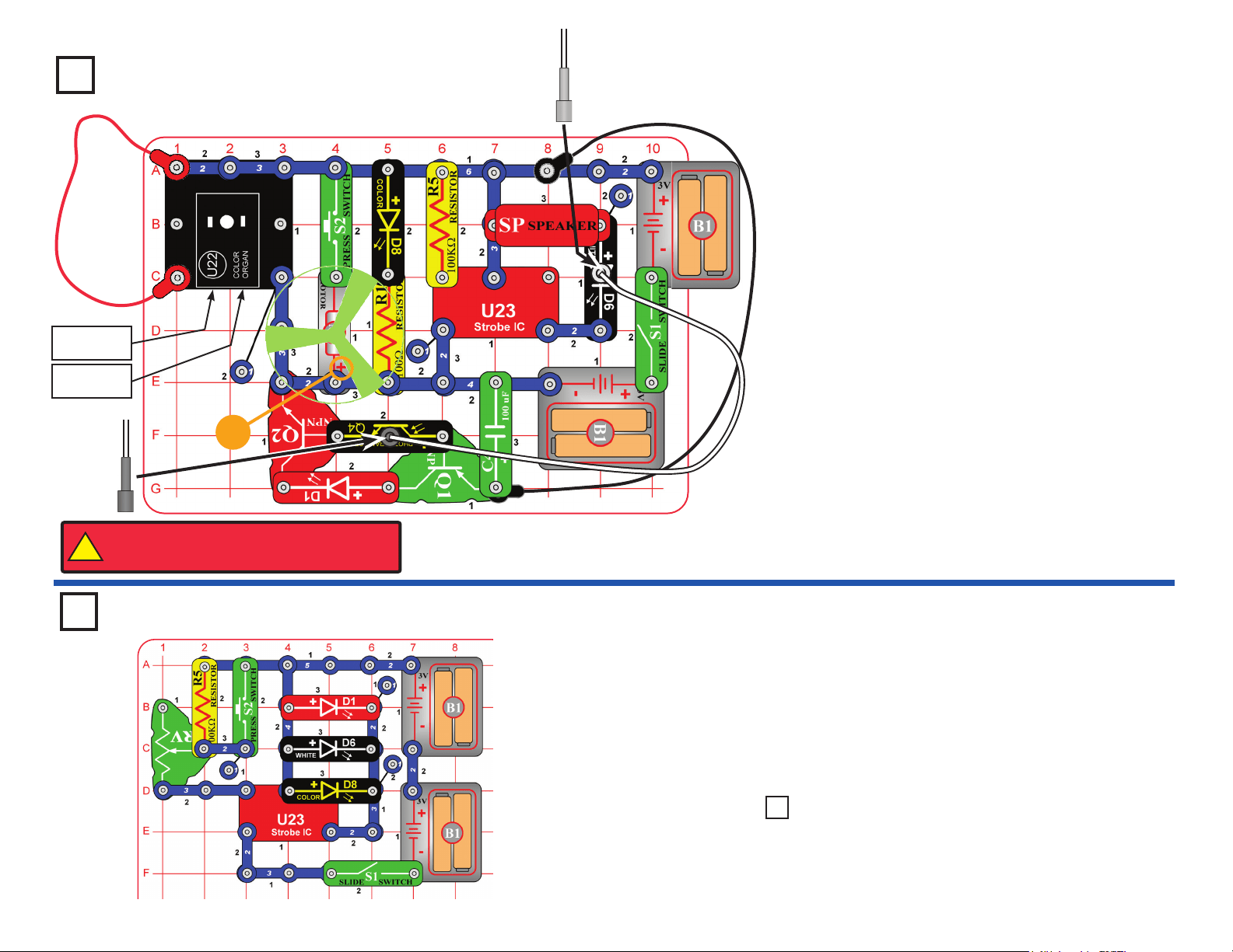
Project 23
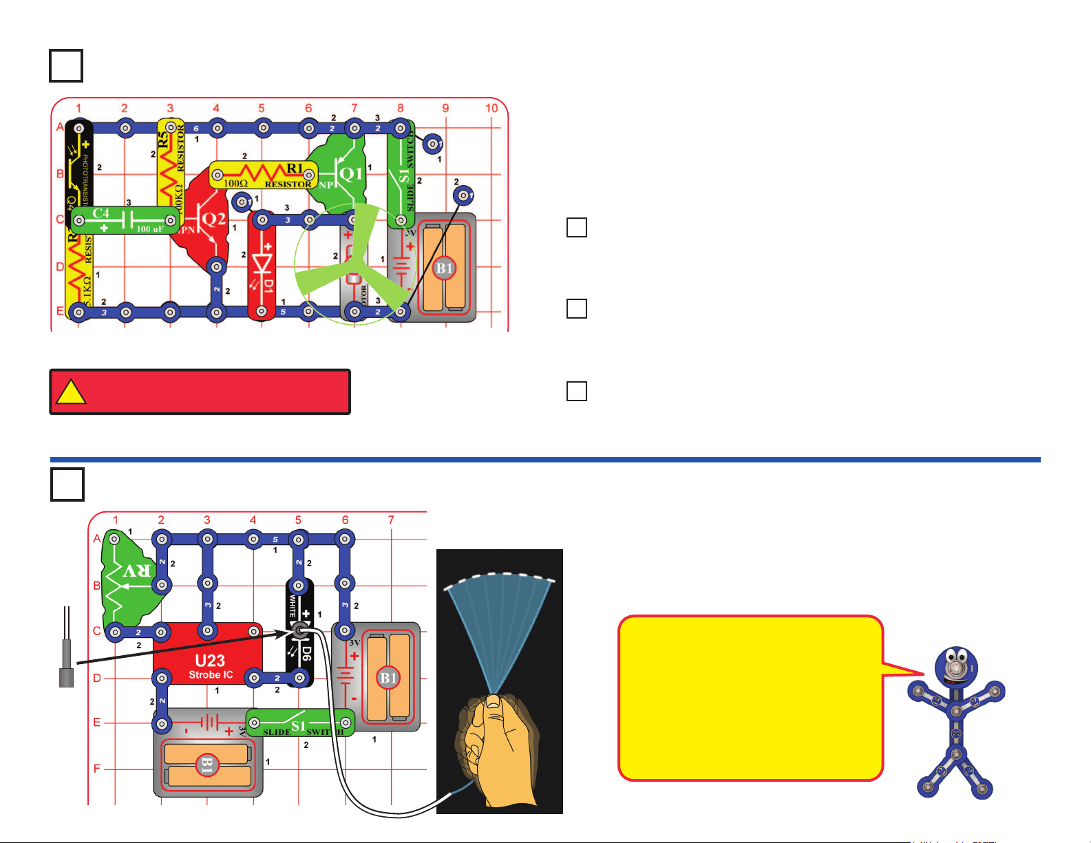
Triple Strobe Light
Build this circuit and turn on the slide switch (S1). Adjust
the blink rate using the lever on the adjustable resistor
(RV), and by pushing the press switch (S2).
Note: In rare cases the circuit may not work at all settings
on RV. If this happens, move the RV lever to the side near
the strobe IC, turn the slide switch off and on to reset the
circuit, and only move the RV lever over a small range.
Use the preceding circuit but replace one of the LEDs
(D1, D6, or D8) with the speaker (SP).
Project 24 Noisy Double
Strobe Light
!
WARNING: Moving parts. Do not touch the fan or
motor during operation. Do not lean over the motor.
25
Project 25
Audio Infrared Detector
You need an infrared remote control for this project, such as any TV/stereo/
DVD remote control in your home.
Build the circuit, set the lever on the adjustable resistor (RV) all the way towards
the infrared module (U24), and turn on the switch (S1). Point your remote
control toward the infrared module and press any button to activate an alarm
sound. The lever on the adjustable resistor sets how long the alarm plays for,
but it only works over a narrow range.
Next, replace the 100W resistor (R1) with the 5.1kW resistor (R3). The alarm
sound is a little different, but the control range on RV is wider.
Sometimes this circuit may activate without a remote control, due to infrared
in sunlight or some room lights. If this happens, try moving to a dark room.
Remote
Project 26
Photo Infrared Detector
Remote
You need an infrared remote control for this project, such as any TV/stereo/
DVD remote control in your home.
Build the circuit and turn on the switch (S1). Place the mounting base
(normally used with the ber optic tree) on the phototransistor (Q4). Set
the lever on the adjustable resistor (RV) so the red LED (D1) just turns off;
if it never turns off, move away from room lights. Point your remote control
directly into the mounting base on Q4, and press any button to activate the
red LED (D1).
The phototransistor can
detect light, and infrared
light is light. The
infrared module (U24) is
designed to focus only
on infrared light.
Sunlight and other light
sources emit some infrared
light, and may activate the
infrared detector. See if
you can activate it without
a remote control.
26
Project 30
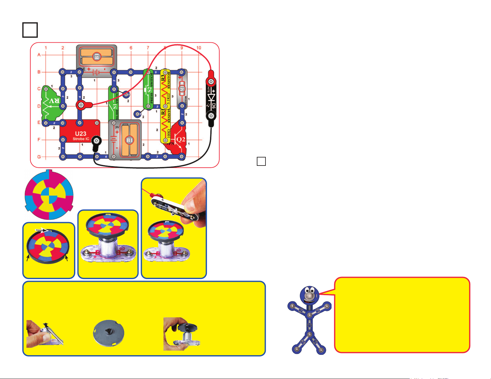
Suspended Raindrops
Build the circuit as shown. Connect the white LED (D6) to the red & black jumper
wires. Turn on the slide switch (S1). Go to a water faucet and adjust the faucet so
water is dripping at a steady rate. Dim the room lights and hold the white LED so
it shines on the dripping water. Try to set the lever on the adjustable resistor (RV)
so that the dipping water drops appear suspended in mid-air. You may need to
adjust the drip rate on the faucet to make this work. You may get better results if
you replace the 100kW resistor (R5) with the 5.1kW resistor (R3). Also, try setting
the strobe rate to minimum and adjusting the drip rate.
Faucet
Project 27
Turn on the slide switch (S1) and move the lever on the adjustable resistor (RV) to
change how fast the light in the color organ (U22) changes colors.
Here the color organ light
changes colors in sync
with the strobe IC (U23),
but at a much slower rate.
Use the preceding circuit but replace the 5.1kW resistor (R3) with the speaker
(SP). Now you also hear the sound change as you adjust the lever on RV.
Project 28 Audio Adjustable Color
Changer
Replace the speaker with one of the LEDs (D1, D6, or D8). The LED is a
strobe light, changing much faster than the LED in the color organ.
Project 29 Double Adjustable Strobe
Adjustable Color Changer
27
Use the preceding circuit, but replace the 3-snap on the adjustable resistor
(RV) with the 100kW resistor (R5). The circuit works the same, but the strobe
rate is much slower (now you can see the LED ashing), so the strobe effects
are different. Slowly adjust the setting on RV as before, and watch the patterns
on the spinning disc.
Note: In rare cases the LED may not ash at all settings on RV. If this
happens, move the RV lever to the side near the strobe IC, turn the slide
switch off and on to reset the circuit, and only move the RV lever over a small
range.
Bonus for owners of other Snap Circuits
®
sets:
If you have a second 100kW
resistor (from model SC-100 / 300 / 500 / 750 or other sets), place it directly
over the R5 that replaced the 3-snap in the above circuit (and place a 1-snap
under one side of the additional R5). Stacking the two 100kW resistors together
creates a “medium” range of strobe speeds, in between the speeds created
with the 3-snap and single 100kW. Adjust the RV setting and watch the strobe
effects as before.
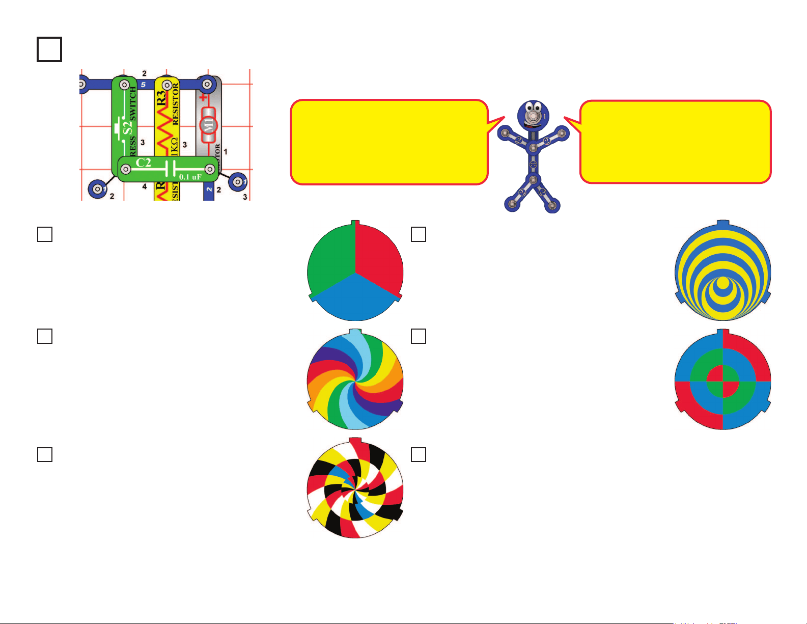
Project 31
Strobe Effects
Build the circuit as shown. Take the colored disc shown and install it into the disc
holder, then place the disc holder on the motor (M1). Connect the white LED (D6) to
the red & black jumper wires.
For best effects, do this in a dimly lit room. Turn on the slide switch (S1). Push the
press switch (S2) until the motor spins continuously (if it stops after you release the
press switch, replace your batteries). Hold the white LED upside down over the disc
holder so it shines on the spinning disc, and move the lever on the adjustable resistor
(RV) slowly while watching the pattern on the spinning disc.
The motor spins the disc so fast that it looks like a blur. However, as you slowly
adjust RV the pattern on the disc appears to slow down, stop, and reverse direction.
Patterns close to the disc center may be moving at different speeds, or in different
directions, from patterns farther from the center! Some patterns may become clear
while others are still blurred.
If the motor does not continue spinning after you release S2, then replace your batteries.
If it still won’t keep spinning then replace the 5.1kW resistor (R3) with a 3-snap wire.
Tab
Slide tabs into slots.
Tab Tab
Place disc holder onto
the motor as shown.
Hold white LED (D6)
over disc as shown.
How does this work? The strobe IC is making the
white LED ash so fast that your eyes think it is on
continuously. RV sets the ash rate, and at some
settings the LED ashes are synchronized with
speed of the patterns spinning on the disc, making
them appear visible instead of blurred.
When the disc pattern is totally blurred, it will appear
as purple, orange, and light green. Combining equal
amounts of red & blue makes purple, red & yellow
makes orange, and yellow & blue makes green.
OPTIONAL (Adult supervision required)
The disc holder rests on the motor top loosely and vibrates, making the disc pattern blurry even when the RV setting makes
the pattern “stop”. The disc patterns will appear clearer if you permanently mount the disc holder to the motor top. This set
contains a spare motor top, which can be used for this. This requires removing the motor top from the motor whenever you
want to switch from using the disc holder to using the glow fan, so is optional, and requires adult supervision.
Project 32 Slow Strobe Effects
If you want
to do this,
pry the
motor top off
the motor
shaft using a
screwdriver.
Lay the spare
motor top in
the disc holder
upside down, and
bond together
with glue (glue
not included).
After the glue dries, push the
modied disc holder on the
motor shaft and install a disc
cutout. When you want to return
to using the glow fan, replace
the motor top disc holder with
the normal motor top.
28
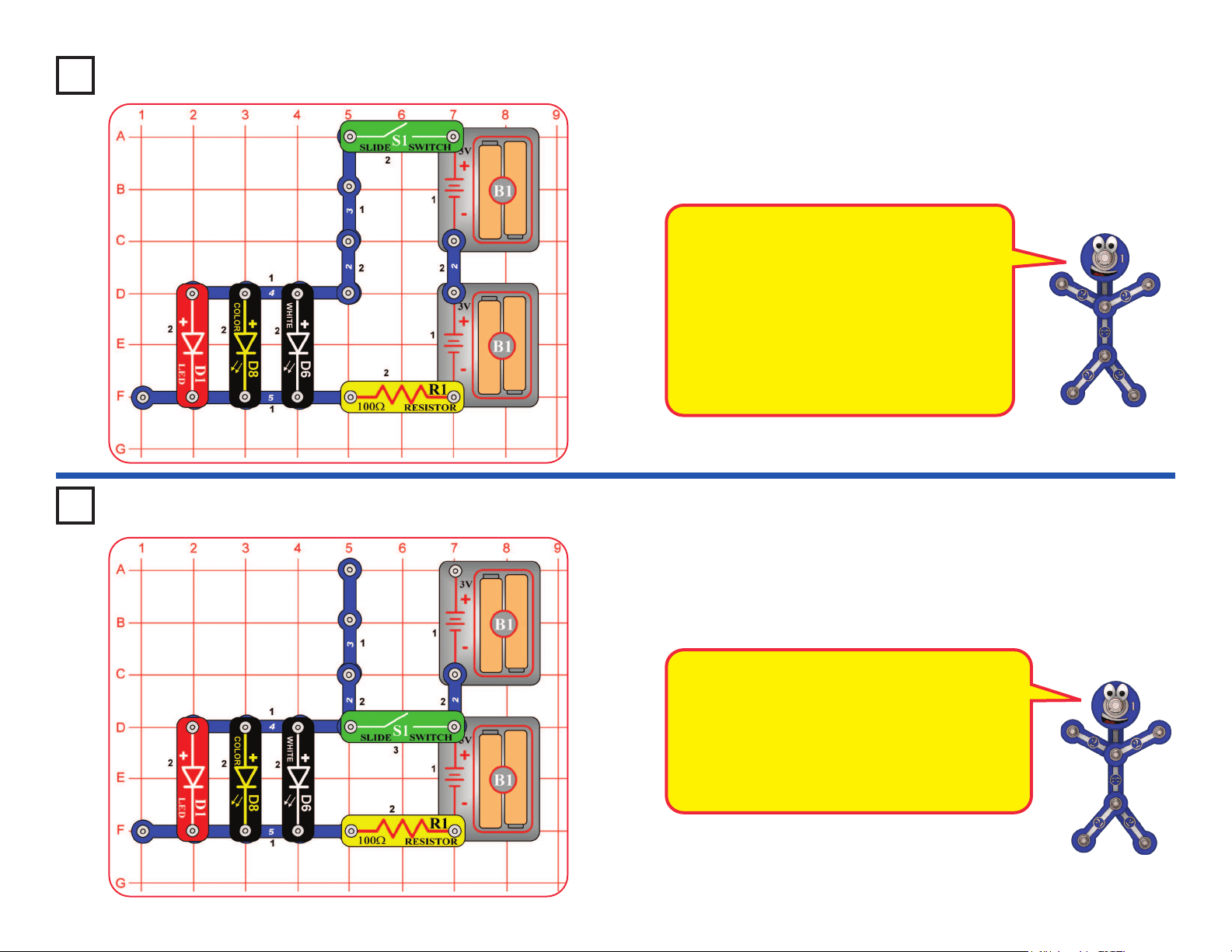
Replace the disc in the disc holder with the one shown
here, and repeat projects 31-33. Observe the strobe
effects. At some RV settings, the rainbow of colors
comes into view.
Project 33
Use the circuits from projects 31 and 32, but add the 0.1mF capacitor (C2) next to the motor, as shown
here. Set the strobe speed so the patterns are visible, and see if they look less blurred than before.
The 0.1mF capacitor has no electrical
effect,but it helps to hold the motor in place
better and reduce vibrations. Less motor
vibration makes the disc holder more
stable, and so makes the patterns a little
clearer. See if you can notice a difference.
Replace the disc in the disc holder with the one
shown here, and repeat projects 31-33. Observe the
strobe effects. To remove a disc from the holder,
use your ngernail, or use a pencil to push it up from
beneath one of the tabs.
When the disc pattern is totally blurred,
it appears to be white. Combining equal
amounts of red, green, and blue makes
white. The LED in the color organ IC
combines red, green, and blue lights to
make white.
Replace the disc in the disc holder with the one
shown here, and repeat projects 31-33. Observe the
strobe effects. With this pattern, some areas may
appear to be moving at different speeds or directions.
Sometimes you can see all the colors on the disc, but
sometimes you can see all the colors except blue,
which is hidden.
Replace the disc in the disc holder with the one
shown here, and repeat projects 31-33. Observe the
strobe effects. This unusual pattern produces several
amazing displays at different RV settings.
Project 34 Strobe Effects (II)
Project 35 Strobe Effects (III)
Project 36 Strobe Effects (IV)
Project 37 Strobe Effects (V)
Project 38 Strobe Effects (VI)
Project 39 Make Your Own Strobe Effects
Replace the disc in the disc holder with the one
shown here, and repeat projects 31-33. Observe the
strobe effects. When the disc pattern is totally blurred,
it will appear as purple, cyan, and yellow. Combining
equal amounts of red & blue makes purple, green &
blue makes cyan, and red & green makes yellow.
Draw your own patterns on paper or cardboard, then cut them to the same
size as our discs. You can also draw patterns on the backs of our discs.
Put them on the disc holder and repeat projects 31-33. Have a contest with
your friends to see who can make the most interesting strobe effects! You
can also nd lots of fun patterns and visual illusions by doing a search on
the internet. There is no limit to what you can do!
Stable Strobe Effects
29
Project 40
LEDs Together
Project 41
LEDs Together (II)
Turn on the slide switch (S1), and compare the brightness of the three LEDs.
Next, remove any of the LEDs and see how the brightness of the others changes.
Modify the preceding circuit by moving the slide switch (S1) to the location shown
here. Compare the brightness of the LEDs. Some LEDs may not turn on.
Next, remove any of the LEDs and see how the brightness of the others changes.
This circuit reduces the voltage to the circuit,
because only one set of batteries is connected.
The limited battery voltage is split between the
R1 resistor and the LEDs. The remaining voltage
across the LEDs is enough to activate the red
LEDs, but may not be enough to activate the other
colors. With the reduced voltage, the red LED will
dominate even more than in the preceding circuit.
The voltage needed for an LED to turn on
depends on the light color. Red light needs the
least, green needs more, but blue and white
need the most. The color LED (D8) contains
red, green, and blue LEDs.
The R1 resistor reduces the voltage available to
the LEDs. The LED brightness varies because
some of the LEDs need more voltage than is
available. The red LED (D1) will dominate the
other colors because it turns on more easily.
30
Project 42
Brightness Control
Build the circuit and turn on the slide switch (S1). Move the lever on the
adjustable resistor (RV) to vary the brightness of the light from the white
LED (D6). If desired, you may place any of the LED attachments (tower,
egg, or ber optic tree) on the LED.
Resistors are used to control or limit the ow of electricity in a circuit.
Higher resistor values reduce the ow of electricity in a circuit.
In this circuit, the adjustable resistor is used to adjust the
LED brightness, to limit the current so the batteries last longer, and
to protect the LED from being damaged by the batteries.
What is Resistance? Take your hands and rub them together very
fast. Your hands should feel warm. The friction between your hands
converts your effort into heat. Resistance is the electrical friction
between an electric current and the material it is owing through.
The adjustable resistor can be set for as low as 200W, or as high as
50,000W (50kW).
The R1 resistor (100W) will have little
effect, since it will be dominated by the
adjustable resistor. Resistor R5 (100kW)
is a high resistance, which greatly
restricts the ow of electricity, so the
LED will be very dim or off. Resistor R3
(5.1kW) will be in between those.
Use the preceding circuit, but replace the 3-snap with one of the yellow
resistors in this set (R1, R3, or R5). Observe how each changes the
LED brightness at different settings for the adjustable resistor.
Use the two preceding circuits, but replace the white LED (D6) with the
red LED (D1) or color LED (D8). Vary the adjustable resistor lever and
change the yellow resistors to see how the light varies with each LED.
Project 43 Resistors
Project 44 Resistors & LEDs
Light Up the FanProject 45
Build the circuit as shown, place the glow fan on the motor (M1), and turn
on the slide switch (S1). Place the circuit in a dark room and push the press
switch (S2) to spin the fan. The color LED (D8) lights up the spinning fan.
The circuit with the color LED is not
electrically connected to the circuit with the
motor. This was done because the motor
produces electrical pulses as it spins, and
these pulses can confuse the color LED.
!
WARNING: Moving parts. Do not touch the fan or
motor during operation. Do not lean over the motor.
31
Project 50
Persistence of Vision
Build the circuit as shown. Place the black ber optic cable holder on the
white LED (D6) and insert the ber cable into the black holder as far as it will
go. Turn on the slide switch (S1). Take the circuit into a dark room and wave
the cable around while watching the loose end. Try it with the lever on the
adjustable resistor (RV) at different settings. The light coming out the loose
end of the ber optic cable will separate into short segments or dashes of light.
Black
“Persistence of Vision” works because the
light is changing faster than your eyes can
adjust. Your eyes continue seeing what they
have just seen.
In a movie theater, lm frames are ashed
on the screen at a fast rate (usually 24 per
second). A timing mechanism makes a light
bulb ash just as the center of the frame is
passing in front of it. Your eyes see this fast
series of ashes as a continuous movie.
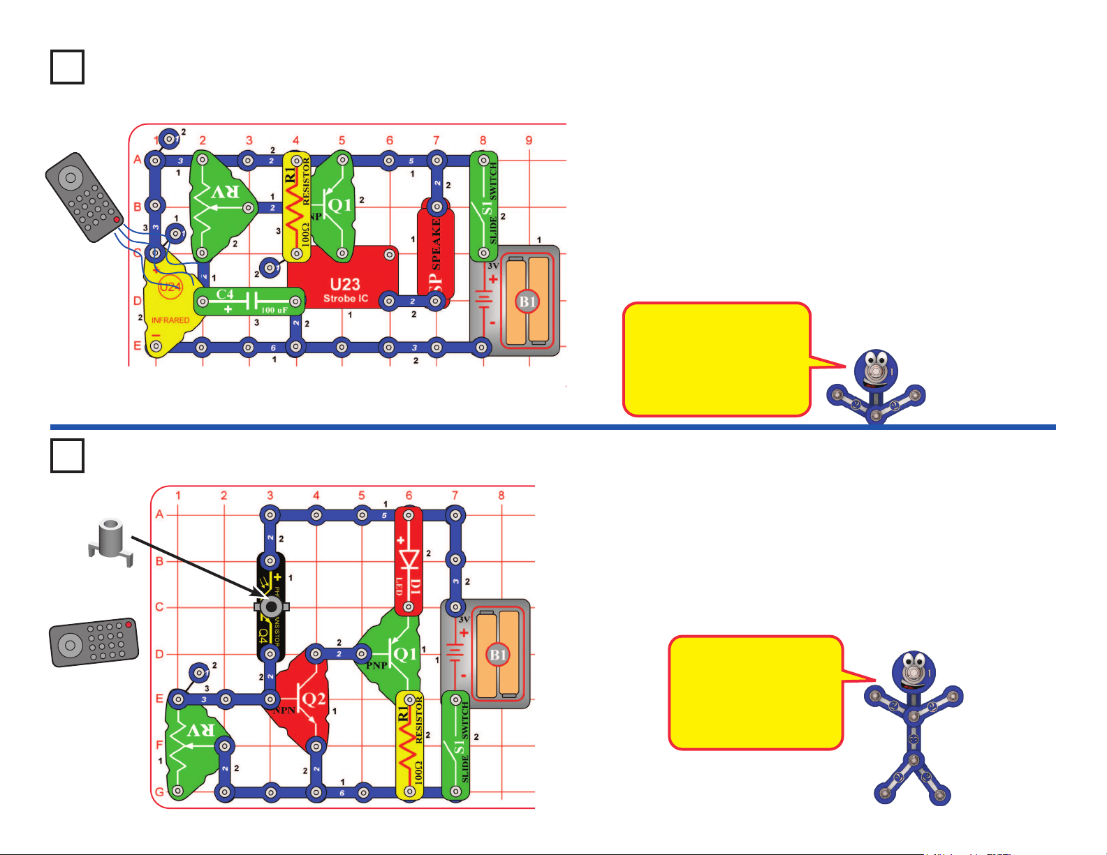
Project 46
Turn on the switch (S1), the motor (M1) spins. As you move your hand over
the phototransistor (Q4), the motor slows. Cover the phototransistor with
your hand. The motor slows down and may stop, but will speed up in a few
seconds. Also try shining a ashlight into the phototransistor.
Use the preceding circuit, but replace the 100mF capacitor (C4) with
the much smaller 0.1mF capacitor (C2). Now varying the light to the
phototransistor has only a small effect on the motor speed.
Use the circuit from project 46, but swap the locations of the phototransistor
(Q4) and 5.1kWresistor (R3); put “+” on Q4 towards C4. Now increasing the
light to the phototransistor slows down the motor, instead of speeding it up.
Project 47 Delayed Speed Control
Project 48 Delayed Speed Control (II)
Use the circuit from project 46, but replace the phototransistor (Q4) with the
microphone (X1, “+” on top). Clap, talk loudly, or blow into the microphone to
change the motor speed.
Project 49 Audio Delayed Speed Control
Delayed Photo
Speed Control
!
WARNING: Moving parts. Do not touch the fan or
motor during operation. Do not lean over the motor.
32
Project 51
This is the same circuit as project 1, but you will view it differently. Turn on
the switch (S1), and view the LED through the prismatic lm (the clear slide).
Prismatic lm makes interesting light effects.
Replace the color LED (D8) with the white LED (D6) and red LED (D1); view
them through the prismatic lm.
View different light sources in and around your home through the
prismatic lm.
Project 52 Look at the Lights
Use the project 51 circuit, but view the color LED through various semi-
transparent liquids, glassware, and plastics. Juices, jello, and cloudy
glass or plastic work well.
Replace the color LED with the white LED (D6). The white LED is
brighter, but does not change color.
Project 53 Scattering Light
Prismatic lm separates light into
different colors. White light is a
combination of all colors.
Semi-transparent materials scatter the
light without completely blocking it, so
a wide area of the liquid or material is
lit up by the light. This happens in the
egg and tower LED attachments.
Use the circuit from project 51, but place the clear cable holder on the
color LED (D8), then place the ber optic cable into the holder as far as
it will go. Turn on the switch, then take the circuit into a dimly lit room
and see the light coming out the open end of the cable. The light travels
through the cable even as you bend it around.
Project 54 Color Fiber Light
Project 55
Blinking Beeping
Build the circuit as shown and turn on the switch (S1). The color LED (D8) will be
blinking and you hear beeping from the speaker. The sound will not be very loud.
The color LED (D8) has a
microcircuit that changes the
light colors. As it does this, it
changes the current through
the circuit. The transistor
(Q2) amplies the changing
current and uses it to control
the speaker (SP).
Use the preceding circuit, but replace the speaker with the red LED (D1).
Now the red LED will also be blinking.
Project 56 Blinking Blinking
Prismatic Film
33
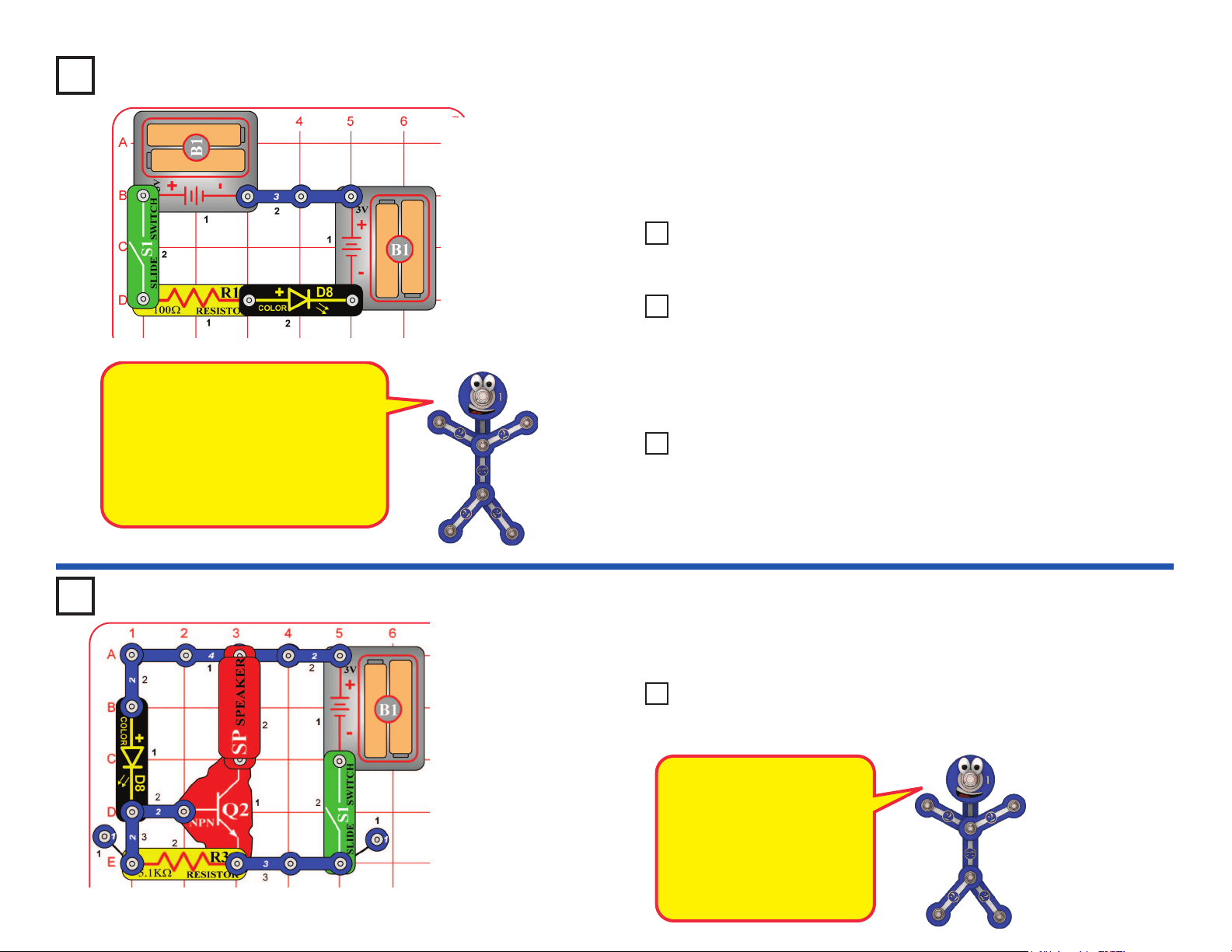
Project 58
Funny Speed Motor
Build the circuit as shown and turn on the switch (S1). The color LED (D8) is
blinking and the motor (M1) spins at different speeds. Try this circuit with the
glow fan on the motor, and without the fan.
The motor is controlled by the color LED using the transistor (Q2). If you
remove the color LED from the circuit then the motor will not spin.
If desired add the red LED (D1) across points A & B (“+” to A). This adds
another blinking light.
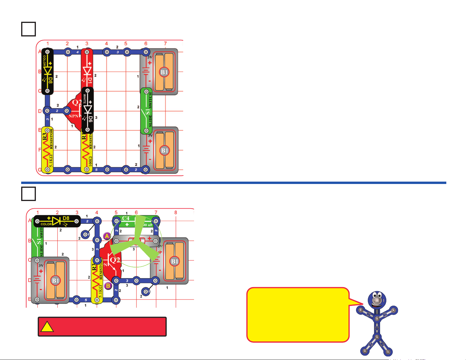
Project 57
Triple Blinker
Build the circuit as shown and turn on the switch (S1). Three LEDs (D1, D6,
and D8) will be blinking.
The red and white LEDs are controlled by the color LED using the transistor
(Q2). If you remove the color LED from the circuit then the other LEDs will
not blink.
In this circuit the color LED is
powered by one set of batteries, and
the motor is powered by different
set. This was done because the
motor produces electrical pulses
as it spins, and these pulses can
confuse the color LED.
!
WARNING: Moving parts. Do not touch the fan or
motor during operation. Do not lean over the motor.
34
Stuck On Light
Build the circuit as shown, and note that several parts are stacked over
others. Turn on the slide switch (S1); nothing happens.
Now push the press switch (S2); the white LED (D6) turns on and stays on.
The white LED will stay on until you turn off the slide switch.
Project 59
The two transistors act
as an electronic device
called an SCR (Silicon
Controlled Rectier). An
SCR is a three-pin device
that once its control pin
is triggered, remains
on until the current ow
through it stops.
Project 61
Build the circuit as shown and turn on the switch (S1). The color LED (D8) is
used to control the strobe IC (U23), producing unusual effects.
Use the preceding circuit, but replace the 100W resistor (R1) with the
color LED (D8) or the red LED (D1).
Project 60 Stuck On Lights
Use the preceding circuit, but
replace the color LED (D8) with the
100kW resistor (R5) or the 5.1kW resistor (R3).
Project 62 Light & Sound
Repeat projects 61 & 62 but replace the speaker with the motor (M1)
and glow fan (motor “+” toward S1).
Project 63 Light & Motion
!
WARNING: Moving parts. Do not touch the fan or
motor during operation. Do not lean over the motor.
Funky Light & Sound
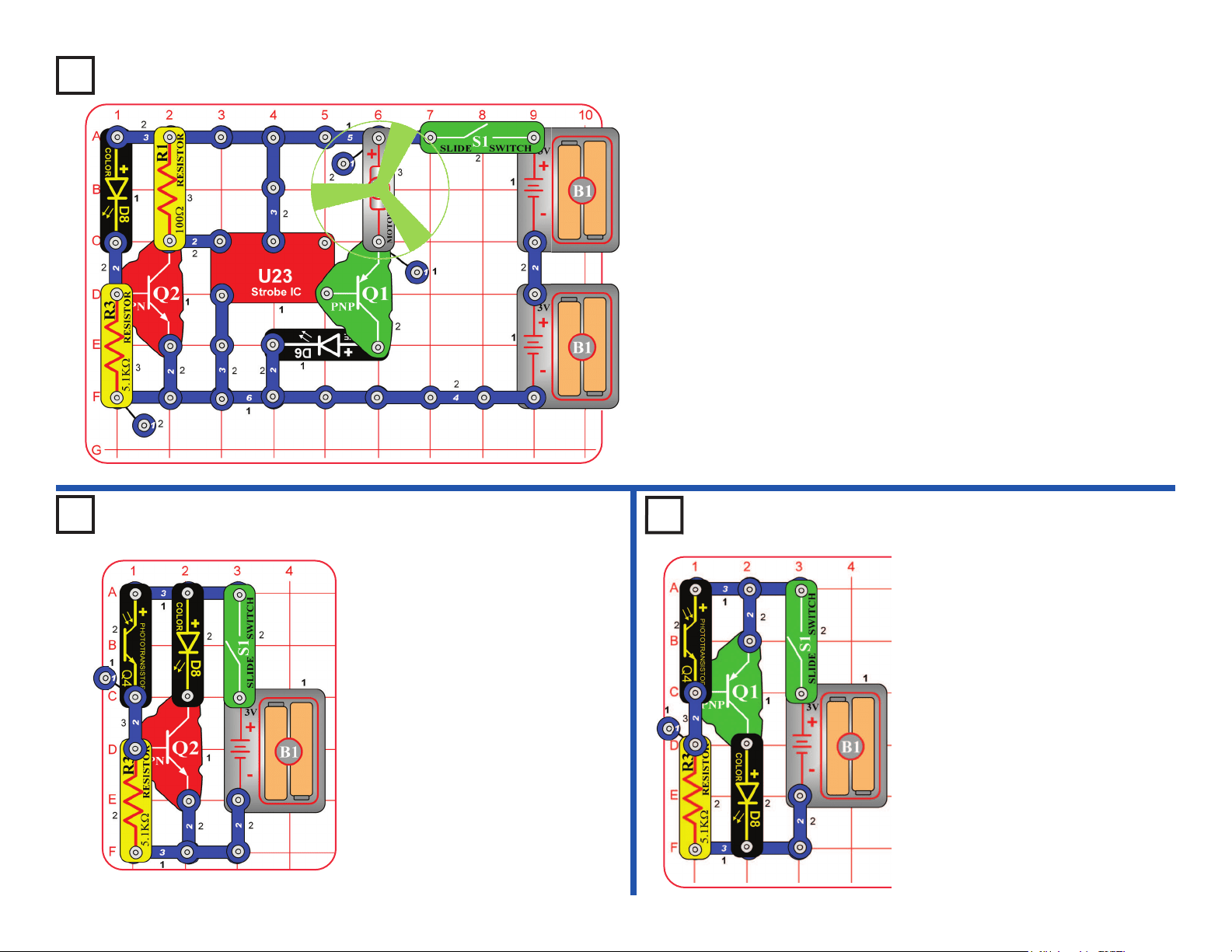
35
Project 64 Blinking Step Motor
Build the circuit as shown and turn on the switch (S1). The color LED (D8)
is used to control the strobe IC (U23), which turns on the motor (M1) in short
bursts.
To have 3 LEDs, place the red LED (D1) directly over the white LED (D6).
Project 65 Day Blinker
Build the circuit as shown and turn
on the switch (S1). The color LED
(D8) is on when there is light on the
phototransistor (Q4). Shine light on
or cover the phototransistor to turn
the color LED on or off.
Build the circuit as shown and
turn on the switch (S1). The
color LED (D8) is off when there
is light on the phototransistor
(Q4). Cover or shine light on the
phototransistor to turn the color
LED on or off.
If the color LED comes on too
easily, reduce the sensitivity by
replacing the 5.1kW resistor (R3)
with the 100kW resistor (R5).
Project 66 Night
Blinker
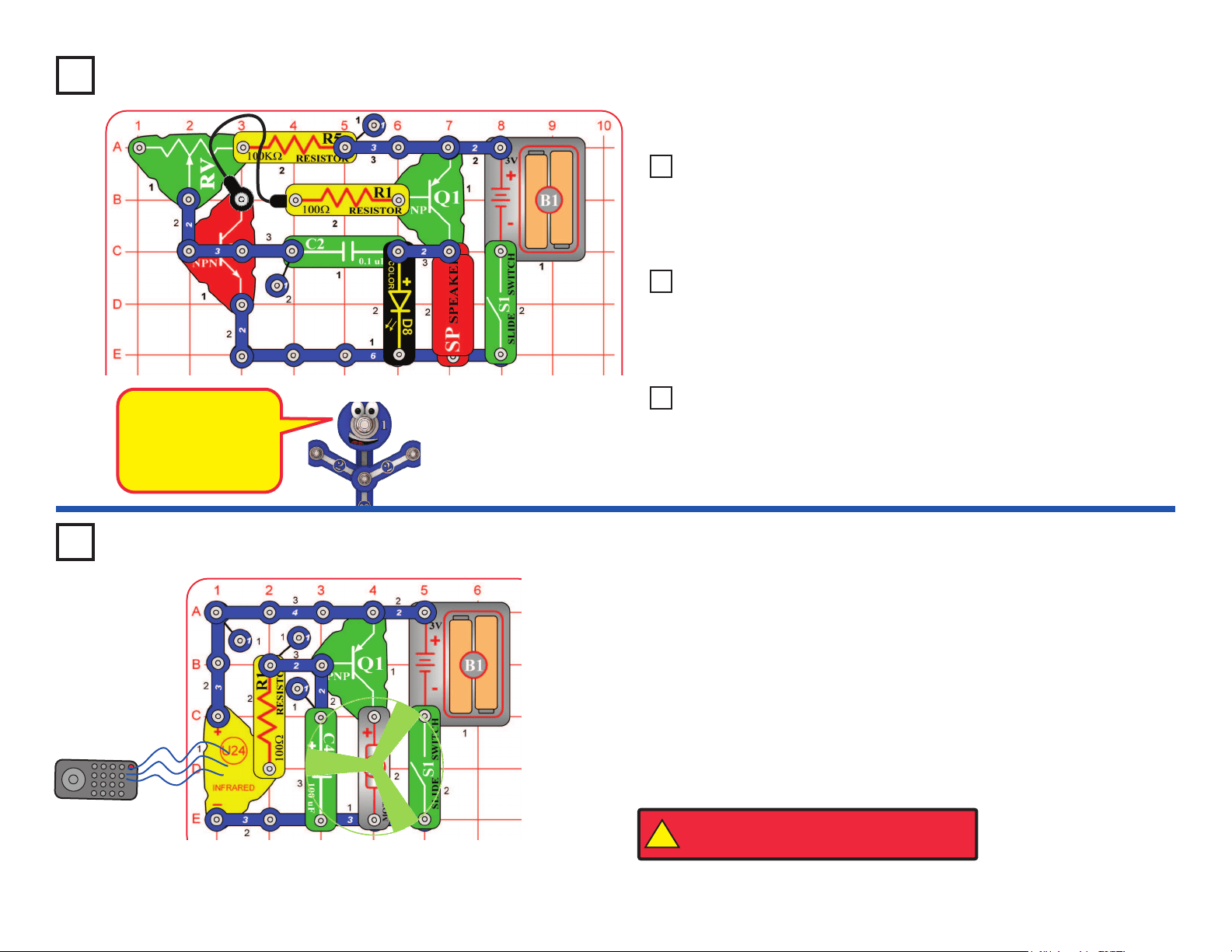
36
Project 67
This circuit is an
oscillator, which
uses feedback to
control the pitch of
the sound.
Build the circuit as shown and turn on the switch (S1). Move the lever on
the adjustable resistor (RV) to vary the pitch of the buzzing sound.
Use the preceding circuit, but place the 5.1kW resistor directly over the
100kW resistor using a 1-snap. The pitch of the tone is higher now,
but the circuit may not make noise on all settings for the adjustable
resistor.
Project 68 Higher Pitch Buzzer
Use the circuits from projects 67-68, but add the phototransistor (Q4)
across base grid locations B2-B4 (between RV and R1, “+” on the left),
on level 3. Vary the amount of light on the phototransistor to change
the sound, while also varying RV.
Project 69 Photo Light & Motion
Use the circuits from projects 67-68, but replace the 0.1mF capacitor
(C2) with the 100mF capacitor (C4), “+” to the right. Turn the switch on
and patiently wait. The speaker will beep and the color LED (D8) will
ash every 5-20 seconds, depending on the resistors.
Project 70 Slow Light & Motion
You need an infrared remote control for this project, such as any TV/stereo/
DVD remote control in your home.
Build the circuit and turn on the switch (S1). Point your remote control toward
the infrared module (U24) and press any button to spin the motor (M1).
Next, remove the 100mF capacitor (C4). The circuit works the same, except
now the motor moves in small steps.
Sometimes this circuit may activate without a remote control, due to infrared
in sunlight or some room lights. If this happens, try moving to a darker room.
Project 71
R/C Motor
Remote
Buzzer
!
WARNING: Moving parts. Do not touch the fan or
motor during operation. Do not lean over the motor.
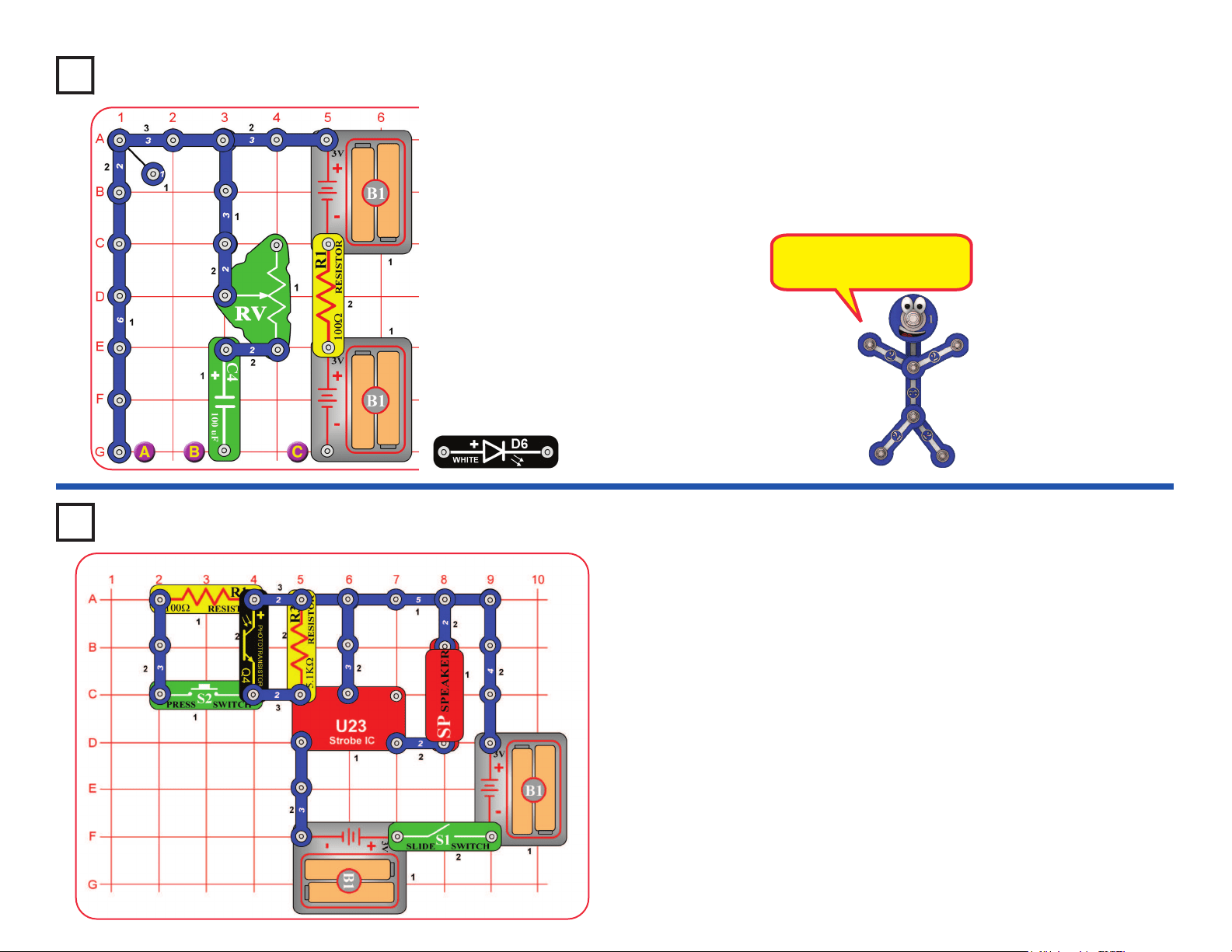
37
Build the circuit and turn on the slide switch (S1). Vary the amount of light on
the phototransistor (Q4) and push the press switch (S2) to change the sound.
Project 73 Wacky Sound Control
Project 72
Build the circuit and set the lever on the adjustable resistor (RV) towards
the 100mF capacitor (C4). Place the white LED (D6) across the points
marked B & C; the LED lights briey as the capacitor charges. Next, place
the white LED across points A & B instead; now the LED lights briey as
the capacitor discharges. Move the white LED back to B & C and repeat.
Use the lever on RV to vary the charge / discharge rate.
The capacitor is storing
energy like a mini battery.
Mini Battery
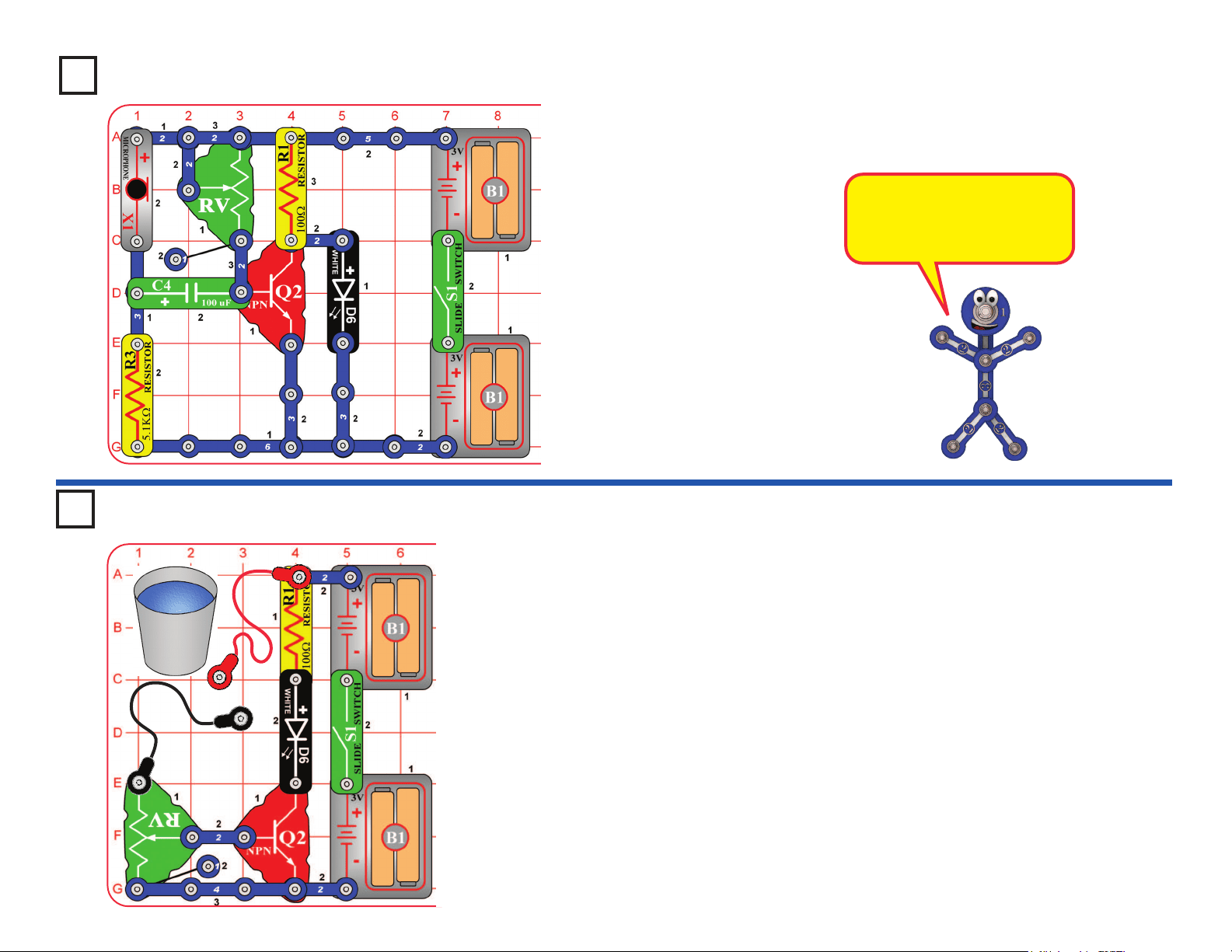
38
Project 74
Blow On the Light
Build the circuit and turn on the slide switch (S1). Set the lever on the
adjustable resistor (RV) to the top. If the white LED (D6) is on, move the lever
on RV until the LED just shuts off. Now blow on the microphone (X1) to turn
the white LED on.
The microphone is a resistor
that changes in value due to
changes in air pressure on its
surface.
Build the circuit and turn on the switch (S1). Touch the metal in the jumper
wire snaps with your ngers. Use the lever on the adjustable resistor (RV)
to adjust the sensitivity of the circuit. You may see a difference in the light
brightness just by pressing the contacts harder with your ngers.
Next, place the loose ends of the jumper wires in a cup of water, make sure
the metal parts aren’t touching each other. The water should change the
light brightness. Readjust sensitivity using RV.
Now add salt to the water and stir to dissolve it. The light should be brighter,
since salt water has less resistance than plain water. Readjust sensitivity
using RV.
WARNING: Don’t drink any water used here.
Project 75 Human & Liquid Light
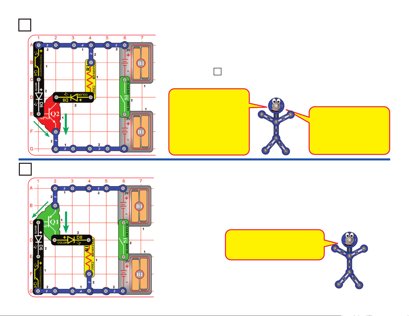
39
Photo Current Amplier
Project 76
Build the circuit, turn on the switch (S1), and vary the amount of light on the
phototransistor (Q4) using your hand. Compare the brightness of the white
LED (D6) and color LED (D8).
Swap the locations of the white and color LEDs, and compare the brightness now.
Project 78
PNP Amplier
This circuit is just like the preceding one except it uses a different type of
transistor. Build the circuit, turn on the switch (S1), and vary the amount of
light on the phototransistor (Q4) using your hand. Compare the brightness of
the white LED (D6) and color LED (D8).
Replace either LED (D6 or D8) with the red LED (D1). Compare all three
LEDs, in both locations.
The NPN transistor (Q2) is a current
amplier. When a small current
ows into Q2 through the left branch
(through Q4), a larger current will
ow into Q2 through the right branch
(with R1). Green arrows shown
thecurrentow. So the LED on
the right side will be brighter than
the LED on the left side. The current
in the right branch might be 100
times larger than in the left branch.
LED brightness depends on the
materials used, construction
quality, and the current through
it. The white LED is super-
bright, the red LED is low-
brightness, and the color LED is
between the others.
The PNP transistor (Q1) is just like the
NPN transistor (Q2), except that the
currents ow in opposite directions.
Greenarrowsshownthecurrentow.
Use the preceding circuit but replace either LED (D6 or D8) with the red
LED (D1). Compare all three LEDs, in both locations.
Project 77 LEDs & Transistors
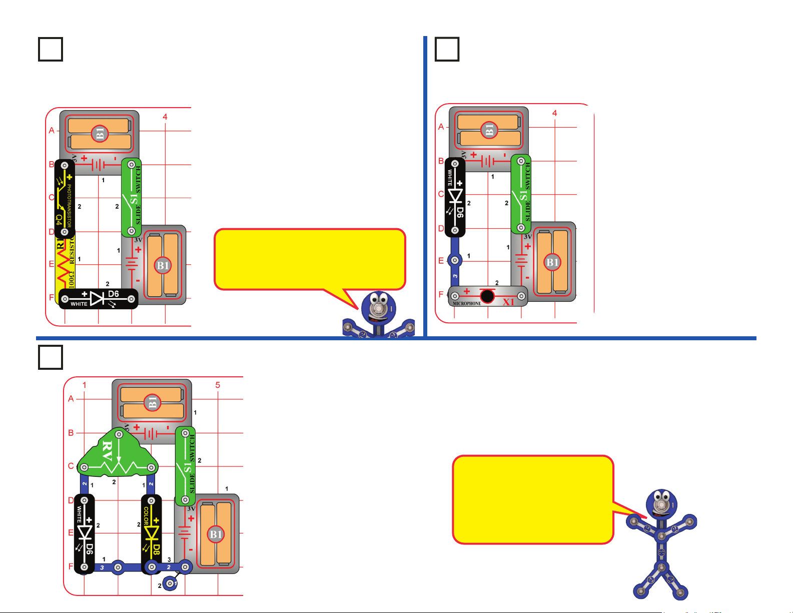
40
Project 81 Resistance Director
Move the lever on the adjustable resistor (RV) across its range and
watch the brightness of the white and color LEDs (D6 & D8).
Replace either LED with the red LED (D1) and compare it too.
You can also replace one of the battery holders (B1) with a 3-snap
wire, and compare the LED brightnesses at lower voltage.
The adjustable resistor can be
adjusted from about 200 ohms to
about 50,000 ohms.
The white LED is a super-bright
LED, so will be brighter than the
others at comparable resistance.
Project 80
Air Pressure Light Control
Project 79
Photo Light Control
Turn on the switch (S1). Control
the white LED (D6) brightness by
varying the amount of light on the
photo-transistor (Q4). Try holding
the red, green, and blue lters
over the phototransistor and see
how they affect it.
Replace the white LED with
the red LED (D1) or the color
LED (D8) and compare them.
Blow on the microphone (X1).
The white LED (D6) will icker,
because the resistance of the
microphone changes when you
blow on it.
Talking into the microphone also
changes its resistance, but you
will not be able to notice the
difference here.
You can replace the white
LED with the red LED (D1) or the
color LED (D8), but they will not
be very bright.
The phototransistor uses light to control
electric current. As more light shines on
the phototransistor, the current through
it increases, making the LED brighter.
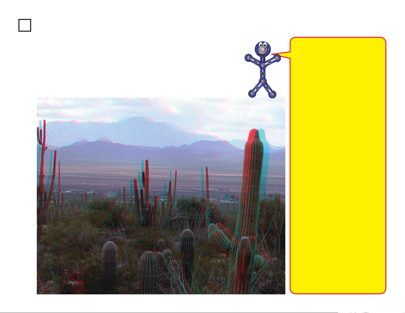
41
Project 82
3D Pictures
Look at the pictures here; they probably look blurry. Now place the red lter in front of your
left eye and the blue lter in front of your right eye, and look at the pictures again. Now the
pictures look clearer, and you can see them in three dimensions (3D).
These pictures contain separate red
& blue images, taken from slightly
different viewpoints, combined together.
When you view them through the red
& blue lters, each eye sees only one
image. Your brain combines the two
images into the single picture that you
“see”, but the differences between the
two images make the combined picture
seem three-dimensional.
How 3D works:
Most people have two eyes, spaced
about 2 inches apart. So each eye
sees the world a little differently, and
your brain uses the difference in views
to calculate distance. For each object
in view, the greater the difference
between the two scenes, the closer it
must be. If you close one eye, you will
have a harder time judging distance –
try catching a ball with just one eye! (Be
sure to use a soft ball if you try playing
catch with one eye.)
When you watch a 3D movie in a
theater, you wear 3D glasses so that
each eye will see a different image.
The movie screen actually shows two
images, and the glasses lter them so
that only one image enters each eye.
Most movie theaters use polarized
images and glasses with polarized
lenses, so that each eye sees a
different image.
Another way to make 3D is using
red & blue images, then view using
glasses with red & blue lters, as you
are doing in this project. Unfortunately
this method does not give you the color
quality that the polarization method has.
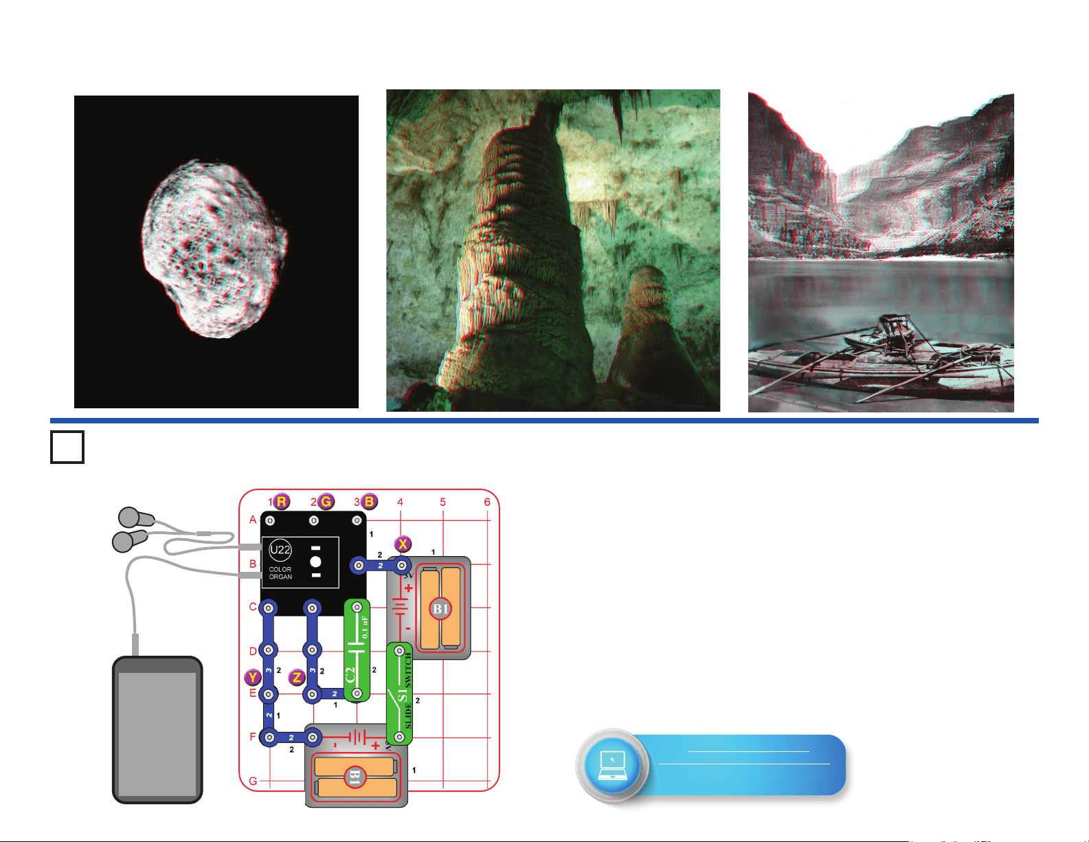
42
3D Pictures
Project 83
Test the Color Organ
This project tests the features of the color organ (U22), and will be
referenced by the Advanced Troubleshooting section on page 15.
A. Build the circuit, and turn on the switch (S1). The light on top of the color
organ should be changing colors.
B. Remove the 0.1mF capacitor (C2), add a 2-snap across the points
marked Y & Z, and reset the circuit by turning it off and on using the
switch. Connect the red jumper wire between the point marked “X”, and
points marked “R”, “G”, or “B” in the drawing. Touching R should make
the light red, G should make it green, and B should make it blue.
C. Remove the 2-snap that was added across points Y & Z. Connect a
music device (not included) and headphones (optional, and not included)
to the color organ as shown, and start music on it. Set the volume control
on your music device so that the light on the color organ is changing (the
light will not change if your volume is set too high or too low).
Headphones & Device
(Optional, not included)
Music
Device
Go to https://shop.elenco.com/
consumers/snap-circuits-light.html
to download projects 84-177
and Bonus Projects 1-11!
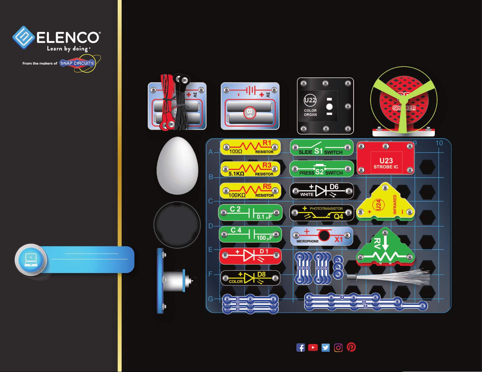
43
1 Base Grid (7.7”x5.5”) overlays some parts, and 6 other are below.
SCL-175 Snap Circuits
®
Light Parts Layout
Snap Circuits
®
, CircuitSafe
®
, Elenco
®
,
Learn By Doing
®
, and Making Coding
a Snap
®
are registered trademarks
of Elenco Electronics, Inc. All rights
reserved. Patents: 7,144,255;
7,273,377; & other patents pending
Important: If any parts
are missing or damaged,
DO NOT RETURN TO
RETAILER. Call toll-free at:
(800) 533-2441 or e-mail us
at: [email protected].
Customer Service: 150
Carpenter Ave. Wheeling, IL
60090 U.S.A.
Note: A complete parts list is
on pages 2-3 in this manual.
www.elenco.com
Not responsible for typographical errors. Colors, styles and case quantities are subject to change without notice.
Go to https://shop.elenco.com/
consumers/snap-circuits-light.html
to download projects 84-177
and Bonus Projects 1-11!