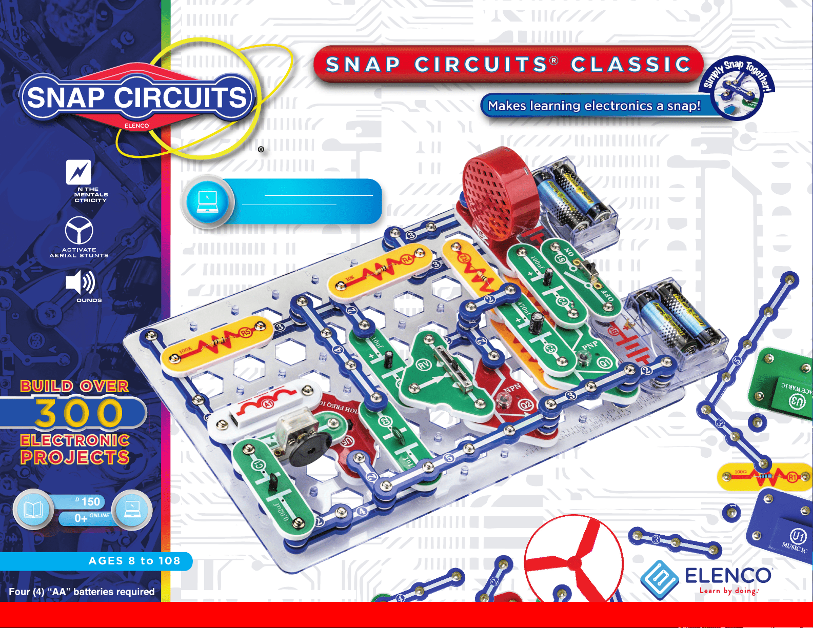
AGES 8 to 108
FUN SOUNDS
LEARN THE
FUNDAMENTALS
OF ELECTRICITY
Projects
PRINTED
150
150+
Projects
ONLINE
Go to shop.elenco.com/consumers/
snap-circuits-classic.html to
download projects 151-305
Copyright © 2021 by Elenco
®
Electronics, Inc. All rights reserved. No part of this book shall be reproduced by 753114
any means; electronic, photocopying, or otherwise without written permission from the publisher.
Patent # 7144255
SOURCE CODE:SC-300V1
Project #139
1
1. Most circuit problems are due to incorrect
assembly, always double-check that your
circuit exactly matches the drawing for it.
2. Be sure that parts with positive/negative
markings are positioned as per the
drawing.
3. Be sure that all connections are securely
snapped.
4. Try replacing the batteries.
5. If the motor spins but does not balance
the fan, check the black plastic piece with
three prongs on the motor shaft. Be sure
that it is at the top of the shaft.
Elenco
®
is not responsible for parts damaged
due to incorrect wiring.
Basic Troubleshooting
Note: If you suspect you have damaged
parts, follow the Advanced Troubleshooting
procedure on page 7 to determine which
ones need replacing.
WARNING: Always check your wiring before
turning on a circuit. Never leave a circuit
unattended while the batteries are installed.
Never connect additional batteries or any other
power sources to your circuits. Discard any
cracked or broken parts.
Adult Supervision: Because children’s
abilities vary so much, even with age groups,
adults should exercise discretion as to
which experiments are suitable and safe (the
instructions should enable supervising adults
to establish the experiment’s suitability for
the child). Make sure your child reads and
follows all of the relevant instructions and
safety procedures, and keeps them at hand for
reference.
This product is intended for use by adults and
children who have attained sufcient maturity
to read and follow directions and warnings.
Never modify your parts, as doing so may
disable important safety features in them, and
could put your child at risk of injury.
Basic Troubleshooting 1
How to Use It 2
Parts List 3-4
About Your Snap Circuits
®
Parts 5-6
Advanced Troubleshooting 7-8
DOs and DON’Ts of Building Circuits 9
Projects 1 - 150 10-60
Table of Contents
WARNING FOR ALL PROJECTS WITH A SYMBOL - Moving parts. Do not touch the motor or fan during operation.
Do not lean over the motor. Do not launch the fan at people, animals, or objects. Eye protection is recommended.
!
!
● Use only 1.5V AA type, alkaline batteries (not
included).
● Insert batteries with correct polarity.
● Non-rechargeable batteries should not be
recharged. Rechargeable batteries should
only be charged under adult supervision, and
should not be recharged while in the product.
● Do not mix old and new batteries.
● Do not connect batteries or battery holders in
parallel.
● Do not mix alkaline, standard (carbon-zinc), or
rechargeable (nickel-cadmium) batteries.
● Remove batteries when they are used up.
● Do not short circuit the battery terminals.
●Never throw batteries in a re or attempt to
open its outer casing.
●Batteries are harmful if swallowed, so keep
away from small children.
●When installing a battery, be sure the spring
is compressed straight back, and not bent up,
down, or to one side.
●Battery installation should be supervised by an
adult.
Batteries:
!
!
Conforms to all applicable U.S.
government requirements and
CAN ICES-3 (B)/NMB-3 (B).
WARNING: SHOCK HAZARD - Never connect Snap
Circuits
®
to electrical outlets in your home in any way!
WARNING: CHOKING HAZARD -
Small parts. Not for children under 3.
Go to shop.elenco.com/consumers/
snap-circuits-classic.html to
download projects 151-305
2
Snap Circuits
®
uses building blocks with
snaps to build the different electrical and
electronic circuits in the projects. Each
block has a function: there are switch
blocks, lamp blocks, battery blocks,
different length wire blocks, etc. These
blocks are in different colors and have
numbers on them so that you can easily
identify them. The circuit you will build
is shown in color and with numbers,
identifying the blocks that you will use
and snap together to form a circuit.
For Example:
This is the switch block which is green
and has the marking on it as shown
in the drawings. Please note that the
drawing doesn’t reect the real switch
block exactly (it is missing the ON and
OFF markings), but gives you the general
idea of which part is being used in the
circuit.
This is a wire block which is blue and
comes in different wire lengths. This one
has the number , , , , or
on it depending on the length of the
wire connection required.
This is a 1-snap wire that is used as a
spacer or for interconnection between
different layers.
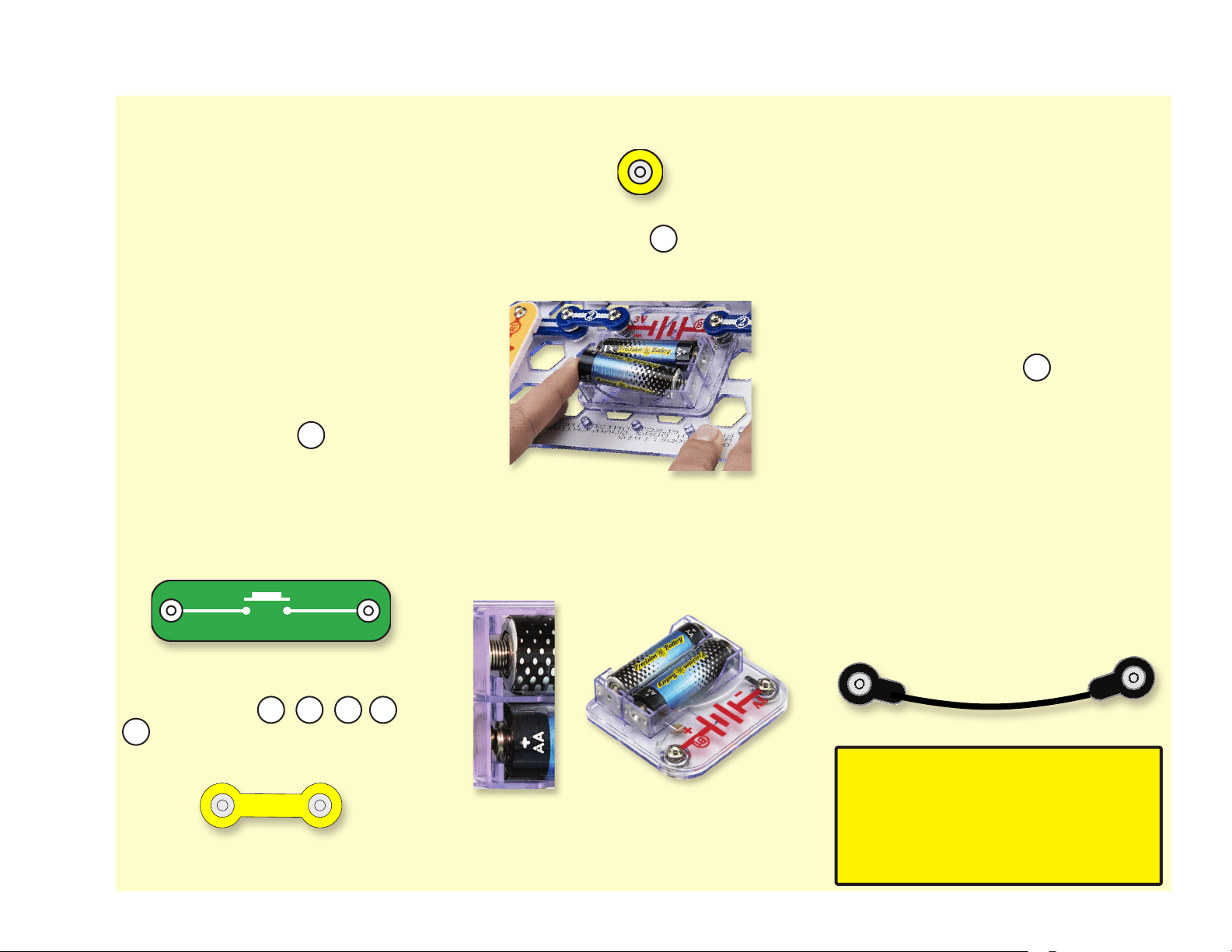
To build each circuit, you have a power
source block number that needs two
(2) “AA” batteries (not included with the
Snap Circuits
®
kit).
When installing a battery, be sure the
spring is compressed straight back, and
not bent up, down, or to one side. Battery
installation should be supervised by an
adult.
A large clear plastic base grid is included
with this kit to help keep the circuit blocks
properly spaced. You will see evenly
spaced posts that the different blocks
snap into. You do not need this base
to build your circuits, but it does help in
keeping your circuit together neatly. The
base has rows labeled A-G and columns
labeled 1-10.
Next to each part in every circuit drawing
is a small number in black. This tells you
which level the component is placed at.
Place all parts on level 1 rst, then all of
the parts on level 2, then all of the parts
on level 3, etc.
Usually when the motor is used, the
fan will usually be placed on it. On top of
the motor shaft is a black plastic piece
(the motor top) with three little tabs. Lay
the fan on the black piece so the slots
in its bottom “fall into place” around the
three tabs in the motor top. If not placed
properly, the fan will fall off when the
motor starts to spin.
Some circuits use the jumper wires to
make unusual connections. Just clip them
to metal snaps or as indicated.
Note: While building circuits, be
careful not to accidentally make a
direct connection across the battery
holder (a “short circuit”), as this may
damage and/or quickly drain the
batteries.
How To Use It
S1
2 3 4 5
6
M1
B1
1
S2
SWITCHPRESS
2
3
Note: If you have the more advanced Models SC-300, SC-500, or SC-750, there are additional part lists in the other project manuals.
Important: If any parts are missing or damaged, DO NOT RETURN TO RETAILER. Call toll-free (800) 533-2441 or e-mail us
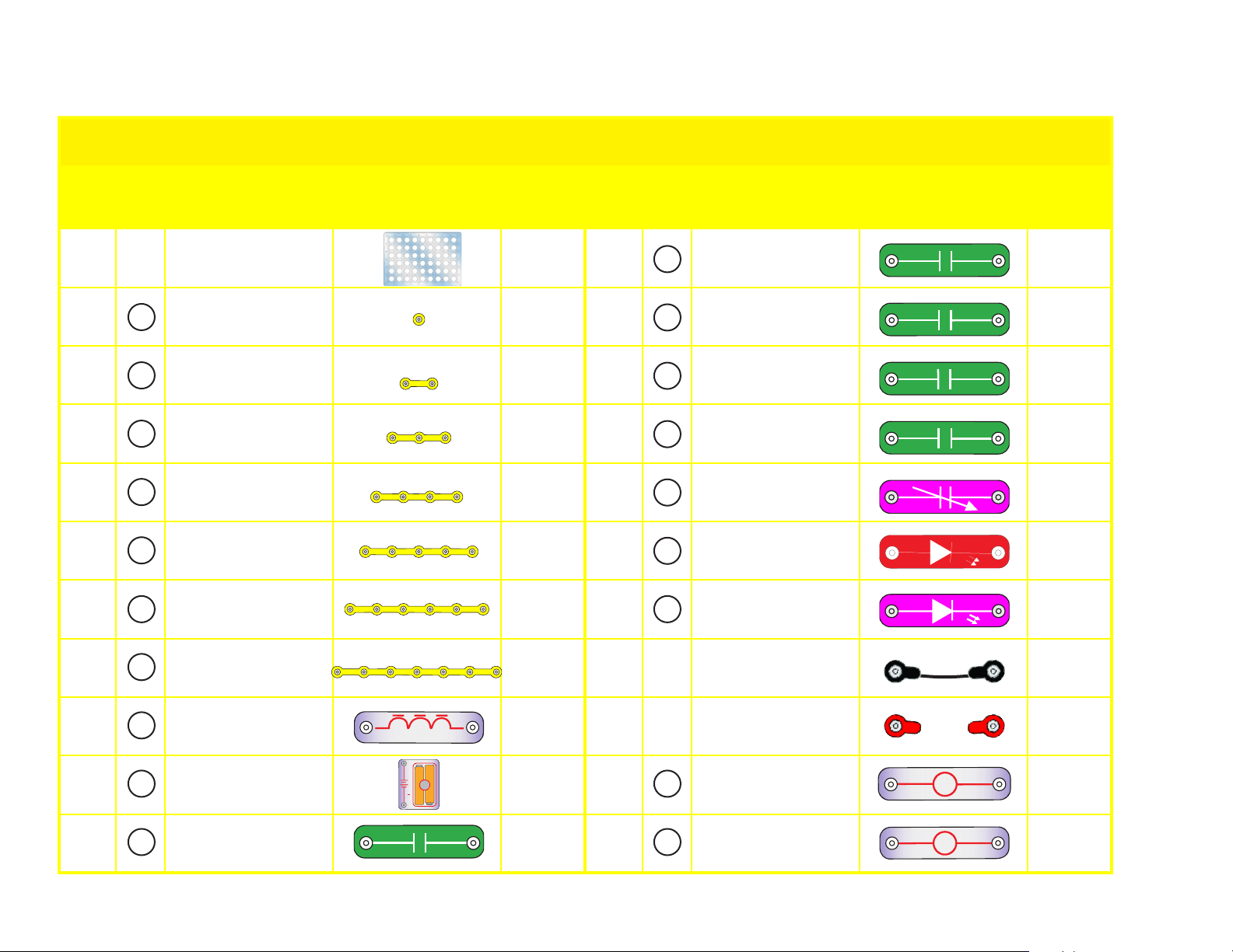
Qty. ID Name Symbol Part # Qty. ID Name Symbol Part #
r 1
Base Grid
(11.0” x 7.7”)
6SCBG
r 1
0.1mF Capacitor 6SCC2
r 6
1-Snap Wire 6SC01
r 1
10mF Capacitor 6SCC3
r 9
2-Snap Wire 6SC02
r 1
100mF Capacitor 6SCC4
r 4
3-Snap Wire 6SC03
r 1
470mF Capacitor 6SCC5
r 2
4-Snap Wire 6SC04
r 1
Variable Capacitor 6SCCV
r 1
5-Snap Wire 6SC05
r 1
Red Light Emitting
Diode (LED)
6SCD1
r 1
6-Snap Wire 6SC06
r 1
Green Light Emitting
Diode (LED)
6SCD2
r 1
7-Snap Wire 6SC07
r 1
Jumper Wire (Black) 6SCJ1
r 1
Antenna Coil 6SCA1
r 1
Jumper Wire (Red) 6SCJ2
r 2
Battery Holder -
uses 2 1.5V type AA
(not Included)
6SCB1
r 1
2.5V or 3V Lamp 6SCL1
r 1
0.02mF Capacitor 6SCC1
r 1
6V Lamp 6SCL2
6
5
4
3
2
1
L1
D1
L 1
LAMP
3V
6
5
4
3
1
Parts List (Colors and styles may vary) Symbols and Numbers
A1
COIL
ANTENNA
+
B1
3V
7
D2
D2
++
L 2
LAMP
6V
C 1
0.02
µ
F
++
100
µ
F
C 4
++
C 5
470
µ
F
+
+
10µF
C 3
C 2
0.1
µ
F
C V
A1
B1
7
L2C1
C2
C5
C4
C3
CV
2
D 1
++
4
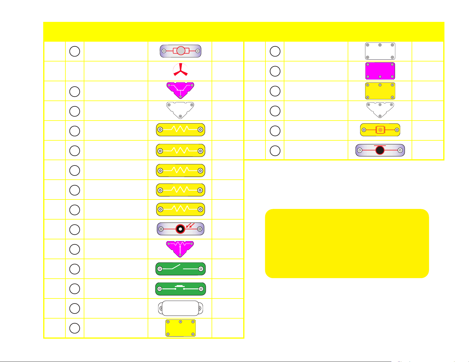
Qty. ID Name Symbol Part # Qty. ID Name Symbol Part #
r 1
Motor 6SCM1
r 1
Alarm
Integrated Circuit
6SCU2
r 1
Fan 6SCM1F
r 1
Space War
Integrated Circuit
6SCU3
r 1
PNP Transistor 6SCQ1
r 1
Power Amplier
Integrated Circuit
6SCU4
r 1
NPN Transistor 6SCQ2
r 1
High Frequency
Integrated Circuit
6SCU5
r 1
100W Resistor 6SCR1
r 1
Whistle Chip 6SCWC
r 1
1kW Resistor 6SCR2
r 1
Microphone 6SCX1
r 1
5.1kW Resistor 6SCR3
r 1
10kW Resistor 6SCR4
r 1
100kW Resistor 6SCR5
r 1
Photoresistor 6SCRP
r 1
Adjustable Resistor 6SCRV
r 1
Slide Switch 6SCS1
r 1
Press Switch 6SCS2
r 1
Speaker 6SCSP
r 1
Music
Integrated Circuit
6SCU1
WC
S1
S2
RP
M1
U3
U2
U1
SP
R1
SPACE WAR IC
U3
MOTOR
M1
+
U2
ALARM IC
U1
MUSIC IC
R1
RESIS
TOR
100Ω
WC
W
H
ISTLE CH
I
P
S1
SWITCH
SLIDE
S2
SWITCHPRESS
RP
PHOTO
RESISTOR
SP
SPEAKER
(STANDING)
U4
AMPLIFIER IC
X1
MICROPHONE
+
R2
RESIS
TO
R
1KΩ
R3
RESIS
TOR
5.1KΩ
RV
Q2
NPN
INTEGRATED CIRCUIT
U5
Q1
PNP
R5
RESISTOR
100KΩ
R4
RESIS
TOR
10KΩ
X1
U4
U5
R5
R4
R3
R2
Q1
Q2
RV
You may order additional / replacement
parts at our website:
www.elenco.com/replacement-parts/

5
(Part designs are subject to change without notice).
The
base grid functions like the printed circuit boards found in most
electronic products. It is a platform for mounting parts and wires (though the
wires are usually “printed” on the board.
The blue
snap wires are just wires used to connect other components, they
are used to transport electricity and do not affect circuit performance. They
come in different lengths to allow orderly arrangement of connections on the
base grid.
The red and black
jumper wires make exible connections for times
when using the snap wires would be difcult. They also are used to make
connections off the base grid (like the projects using water).
The
batteries (B1) produce an electrical voltage using a chemical reaction.
This “voltage” can be thought of as electrical pressure, pushing electrical
“current” through a circuit. This voltage is much lower and much safer than
that used in your house wiring. Using more batteries increases the “pressure”
and so more electricity ows.
The
slide switch (S1) connects (ON) or disconnects (OFF) the wires in a
circuit. When ON it has no effect on circuit performance.
The
press switch (S2) connects (pressed) or disconnects (not pressed) the
wires in a circuit, just like the slide switch does.
Resistors “resist” the ow of electricity and are used to control or limit the
electricity in a circuit. Snap Circuits
®
includes
100W (R1), 1KW (R2), 5.1KW
(R3), 10KW (R4), and 100KW (R5) resistors
(“K” symbolizes 1,000, so R3
is really 5,100W). Materials like metal have very low resistance (<1W) and
are called conductors, while materials like paper, plastic, and air have near-
innite resistance and are called insulators. Increasing circuit resistance
reduces the ow of electricity.
The
adjustable resistor (RV) is a 50KW resistor but with a center tap that
can be adjusted between 0W and 50KW. At the 0W setting, the current must
be limited by the other components in the circuit.
The
photoresistor (RP) is a light-sensitive resistor, its value changes from
nearly innite in total darkness to about 1000W when a bright light shines on it.
The
microphone (X1) is actually a resistor that changes in value when
changes in air pressure (sounds) apply pressure to its surface. Its resistance
typically varies from around 1KW in silence to around 10KW when you blow
on it.
A light bulb, such as in the
2.5V and 6V lamps (L1 and L2), contains a
special wire that glows bright when a large electric current passes through it.
Voltages above the bulb’s rating can burn out the wire.
The
motor (M1) converts electricity into mechanical motion. Electricity is
closely related to magnetism, and an electric current owing in a wire has a
magnetic eld similar to that of a very, very tiny magnet. Inside the motor is
three coils of wire with many loops. If a large electric current ows through
the loops, the magnetic effects become concentrated enough to move the
coils. The motor has a magnet inside so, as the electricity moves the coils to
align them with the permanent magnet, the shaft spins.
The
speaker (SP) converts electricity into sound. It does this by using
the energy of a changing electrical signal to create mechanical vibrations
(using a coil and magnet similar to that in the motor), these vibrations create
variations in air pressure which travel across the room. You “hear” sound
when your ears feel these air pressure variations.
The
whistle chip (WC) contains two thin plates. When an electrical signal is
applied across them they will stretch slightly in an effort to separate (like two
magnets opposing each other), when the signal is removed they come back
together. If the electrical signal applied across them is changing quickly, then
the plates will vibrate. These vibrations create variations in air pressure that
your ears feel just like sound from a speaker.
The
red and green LEDs (D1 and D2) are light emitting diodes, and may
be thought of as a special one-way light bulb. In the “forward” direction
(indicated by the “arrow” in the symbol) electricity ows if the voltage exceeds
a turn-on threshold (about 1.5V for red and 2V for green); brightness then
increases. A high current will burn out the LED, Snap Circuits
®
LEDs have
internal resistors to protect them. LEDs block electricity in the “reverse”
direction.
Capacitors are components that can store electrical pressure (voltage) for
periods of time, higher values have more storage. Because of this storage
ability they block unchanging voltage signals and pass fast changing
voltages. Capacitors are used for ltering and oscillation circuits. Snap
Circuits
®
includes
0.02mF (C1), 0.1mF (C2), 10mF (C3), 10mF (C4), 470mF
(C5) capacitors, and a variable capacitor (CV).
The variable capacitor can
be adjusted from .00004 to .00022mF and is used in high frequency radio
circuits for tuning. The whistle chip (WC) also acts like a 0.02mF capacitor in
addition to its sound properties.
The
antenna (A1) contains a coil of wire wrapped around an iron bar.
Although it has magnetic effects similar to those in the motor, those effects
are tiny and may be ignored except at high frequencies (like in AM radio).
About Your Snap Circuits
®
Parts
Our Student Guides give much more information about your parts along with a complete lesson
in basic electronics. See www.elenco.com/faqs for more information.
6
Its magnetic properties allow it to concentrate radio signals for reception. At
lower frequencies the antenna acts like an ordinary wire.
The
PNP (Q1) and NPN (Q2) transistors are components that use a small
electric current to control a large current, and are used in switching, amplier,
and buffering applications. They are easy to miniaturize, and are the main
building blocks of integrated circuits including the microprocessor and
memory circuits in computers. Projects #65-66 demonstrate their properties.
A high current may damage a transistor, so the current must be limited by
other components in the circuit.
Some types of electronic components can be super-miniaturized, allowing
many thousands of parts to t into an area smaller that your ngernail. These
“integrated circuits” (ICs) are used in everything from simple electronic toys
to the most advanced computers. The music, alarm, and space war ICs (U1,
U2, and U3) in Snap Circuits
®
are actually modules containing specialized
sound-generation ICs and other supporting components (resistors,
capacitors, and transistors) that are always needed with them. This was done
to simplify the connections you need to make to use them. The descriptions
for these modules are given here for those interested, see the projects for
connection examples:
The
power amplier IC (U4) is a module containing an integrated circuit
amplier and supporting components that are always needed with it. A
description of it is given here for those interested:
The
high frequency IC (U5) is a specialized amplier used only in high
frequency radio circuits. A description of it is given here for those interested:
About Your Snap Circuits
®
Parts
INTEGRATED CIRCUIT
U5
INP INP(–)
OUT
High Frequency IC:
INP - input connection (2 points are same)
OUT - output connection
(–) power return to batteries
See project #52 for example of connections.
SPACE WAR IC
U3
IN1
(+)
OUT
IN2
(–)
Space War IC:
(+) - power from batteries
(–) - power return to batteries
OUT - output connection
IN1, IN2 - control inputs
Connect each control input to (–)
power to sequence through 8 sounds.
U1
MUSIC IC
(+)
HLD
OUT
(–)
TRG
Music IC:
(+) - power from batteries
(–) - power return to batteries
OUT - output connection
HLD - hold control input
TRG - trigger control input
Music for a few seconds on power-up, then hold HLD to
(+) power or touch TRG to (+) power to resume music.
U2
ALARM IC
IN1
(–)
IN2
IN3
OUT
Alarm IC:
IN1, IN2, IN3 - control inputs
(–) - power return to batteries
OUT - output connection
Connect control inputs to (+) power to make ve
alarm sounds, see project 14 for congurations.
U4
AMPLIFIER IC
INP
FIL
(+)
OUT
(–)
Power Amplier IC:
(+) - power from batteries
(–) - power return to batteries
FIL - ltered power from batteries
INP - input connection
OUT - output connection
See project #52 for example of connections.
7
If you suspect you have damaged parts, you can follow this
procedure to systematically determine which ones need
replacing:
1. 2.5V/3V lamp (L1), 6V lamp (L2), motor (M1), speaker (SP), and
battery holder (B1): Place batteries in holder. Place each lamp
directly across the battery holder, each should light and L1 should
be brighter. Do the same with the motor (motor + to battery +), it
should spin to the right at high speed. “Tap” the speaker across the
battery holder contacts, you should hear static as it touches. If none
work, then replace your batteries and repeat, if still bad then the
battery holder is damaged.
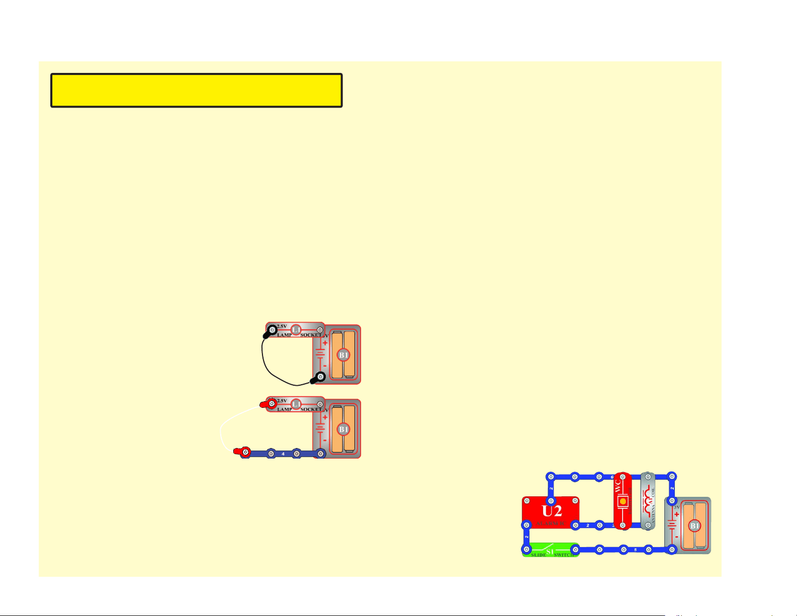
2. Jumper wires: Use this mini-circuit
to test each jumper wire, the lamp
should light.
3. Snap wires: Use this mini-circuit to
test each of the snap wires, one at
a time. The lamp should light.
4.
Slide switch (S1) and Press switch (S2): Build project #1, if the
lamp (L1) doesn’t light then the slide switch is bad. Replace the
slide switch with the press switch to test it.
5.
100W (R1), 1KW (R2), 5.1KW (R3), and 10KW (R4) resistors, red
LED (D1), and green LED (D2): Build project #7 except initially use
the speaker (SP) in place of the resistor, the red LED should light.
Replace the red LED with the green LED and it should light. Then
replace the speaker with each resistor; the LED should light and
the brightness decreases with the higher value resistors.
6. Alarm IC (U2): Build project #14, you should hear a siren. Then
place a 3-snap wire between grid locations A1 and C1, the sound is
different. Then move the 3-snap from A1-C1 to A3-C3 to hear a 3rd
sound.
7. Music IC (U1): Build project #13. Turn it on and the sound plays for
a while and stops, it resumes if you press and hold down the press
switch. Then touch a 3-snap wire across base grid points A1 and C1
and the sound resumes for a while.
8. Space war IC (U3) and photoresistor (RP): Build project #15, both
switches (S1 and S2) should change the sound. Then replace the
slide switch with the photoresistor, waving your hand over it should
change the sound.
9. Whistle chip (WC): Build project #35 and if there is light on the
photoresistor (RP) then you will hear sound from the whistle chip.
10. Antenna (A1): Build
the mini-circuit shown
here, you should hear
sound.
Advanced Troubleshooting (Adult supervision recommended)
Elenco
®
is not responsible for parts damaged due to
incorrect wiring.
8
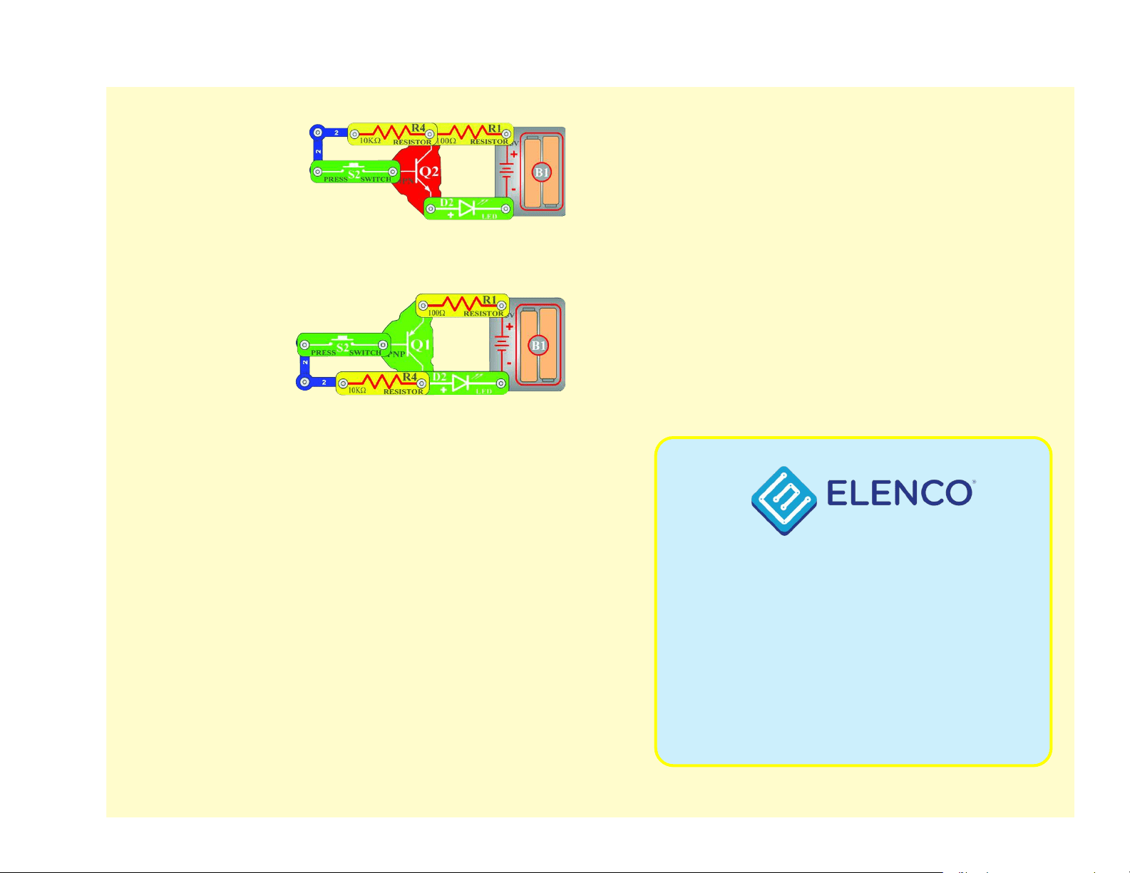
11. NPN transistor (Q2):
Build the mini-circuit
shown here. The LED
(D2) should only be on
if the press switch (S2)
is pressed. If otherwise,
then the NPN is
damaged.
12. PNP transistor
(Q1): Build the
mini-circuit shown
here. The LED (D1)
should only be on
if the press switch
(S2) is pressed.
Otherwise, the PNP
is damaged.
13. Adjustable resistor (RV): Build project #65, the resistor control
can turn the Lamp (L2) on and off.
14. 100WK resistor (R5) and 0.02mF (C1), 0.1mF (C2), and 10mF (C3)
capacitors: Build project #147, it makes sound unless the resistor
is bad. Place the 0.02mF capacitor on top of the whistle chip (WC)
and the sound changes (pitch is lower). Replace the 0.02mF with
the 0.1mF and the pitch is even lower. Replace the 0.1mF with the
10mF and the circuit will “click” about once a second.
15. 100mF (C4) and 470mF (C5) capacitors: Build project #120,
press the press switch (S2) and turn on the slide switch (S1). The
LED (D1) should be lit for about 15 seconds then go out (press
the press switch again to reset this). Replace the 470mF with the
100mF and the LED is only lit for about 4 seconds now.
16. Power Amplier IC (U4): Build project 124, adjusting RV should
change the sound.
17. Microphone (X1): Build project #23, blowing into the microphone
should turn off the lamp (L2).
18. Variable Capacitor (CV): Build project #113 and place it near an
AM radio, tune the radio and the capacitor to verify you hear the
music on your radio.
19. High Frequency IC (U5): Build project #52 and adjust the variable
capacitor (CV) and adjustable resistor (RV) until you hear a radio
station.
Advanced Troubleshooting (Adult supervision recommended)
150 Carpenter Avenue
Wheeling, IL 60090 U.S.A.
Phone: (847) 541-3800
Fax: (847) 520-0085
e-mail: [email protected]
Website: www.elenco.com
You may order additional / replacement parts at:
www.elenco.com/replacement-parts/
9
After building the circuits given in this booklet, you may wish to experiment on your
own. Use the projects in this booklet as a guide, as many important design concepts
are introduced throughout them. Every circuit will include a power source (the batteries),
a resistance (which might be a resistor, lamp, motor, integrated circuit, etc.), and
wiring paths between them and back.
You must be careful not to create "short circuits"
(very low-resistance paths across the batteries, see examples below) as this will
damage components and/or quickly drain your batteries.
Only connect the ICs using
congurations given in the projects, incorrectly doing so may damage them. Elenco
®
is
not responsible for parts damaged due to incorrect wiring.
You are encouraged to tell us about new circuits you create. If they are
unique, we will post them with your name and state on our website at
www.elenco.com/for-makers. Send your suggestions to
Elenco
®
provides a circuit designer so that you can make your own
Snap Circuits
®
drawings. This Microsoft
®
Word document can be
downloaded from www.elenco.com/for-makers.
Examples of SHORT CIRCUITS - NEVER DO THESE!!!
WARNING: SHOCK HAZARD - Never connect Snap Circuits
®
to
the electrical outlets in your home in any way!
DOs and DON’Ts of Building Circuits
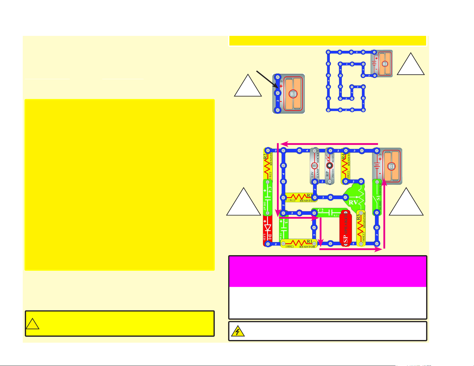
Placing a 3-snap wire
directly across the batteries
is a SHORT CIRCUIT.
This is also a
SHORT CIRCUIT.
When the slide switch (S1) is turned on, this large circuit has a SHORT
CIRCUIT path (as shown by the arrows). The short circuit prevents any
other portions of the circuit from ever working.
NEVER
DO!
!
NEVER
DO!
!
!!
NEVER
DO!
NEVER
DO!
Here are some important guidelines:
ALWAYS USE EYE PROTECTION WHEN EXPERIMENTING ON YOUR OWN.
ALWAYS include at least one component that will limit the current through a circuit,
such as the speaker, lamp, whistle chip, capacitors, ICs (which must be
connected properly), motor, microphone, photoresistor, or resistors (the
adjustable resistor doesn’t count if it’s set at/near minimum resistance).
ALWAYS use transistors, the high frequency IC, the antenna, and switches in
conjunction with other components that will limit the current through them.
Failure to do so will create a short circuit and/or damage those parts.
ALWAYS connect the adjustable resistor so that if set to its 0 setting, the current
will be limited by other components in the circuit.
ALWAYS connect position capacitors so that the “+” side gets the higher voltage.
ALWAYS disconnect your batteries immediately and check your wiring if something
appears to be getting hot.
ALWAYS check your wiring before turning on a circuit.
ALWAYS connect ICs using congurations given in the projects or as per the
connection descriptions for the parts.
NEVER try to use the high frequency IC as a transistor (the packages are similar,
but the parts are different).
NEVER use the 2.5V lamp in a circuit with both battery holders unless you are sure
that the voltage across it will be limited.
NEVER connect to an electrical outlet in your home in any way.
NEVER leave a circuit unattended when it is turned on.
NEVER touch the motor when it is spinning at high speed.
Warning to Snap Circuits
®
owners: Do not connect additional
voltage sources from other sets, or you may damage your parts.
Contact ELENCO
®
if you have questions or need guidance.
!
For all of the projects given in this book, the parts may be arranged in different ways
without changing the circuit. For example, the order of parts connected in series or in
parallel does not matter — what matters is how combinations of these sub-circuits are
arranged together.
10
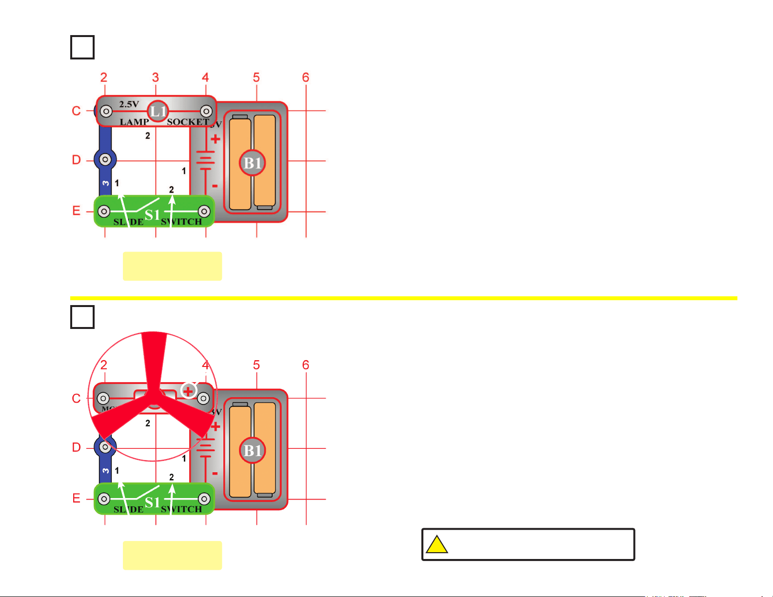
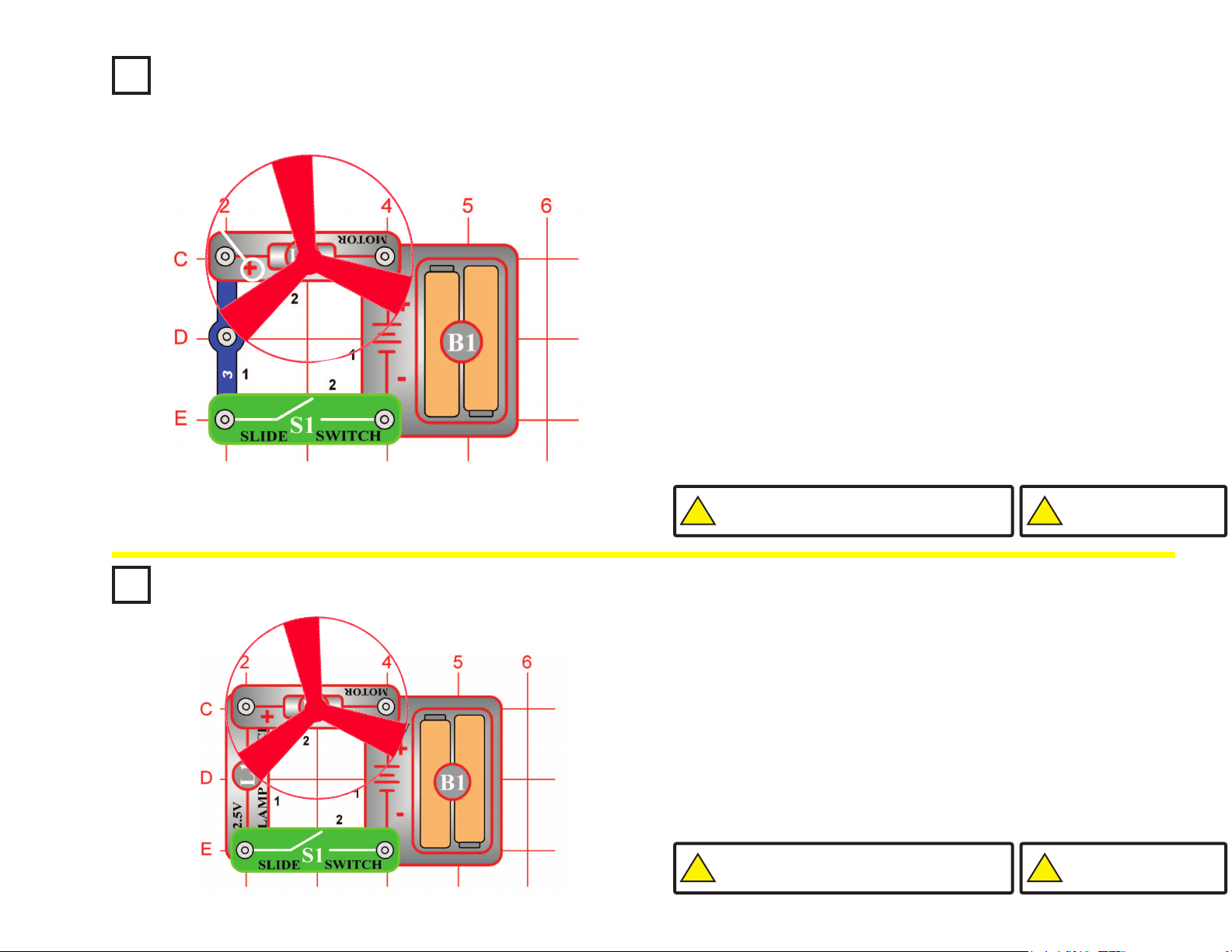
Project #1 Electric Light & Switch
OBJECTIVE: To show how electricity is turned “ON” or
“OFF” with a switch.
Project #2
Build the circuit shown on the left by placing all the parts with a black 1
next to them on the base grid rst. Then, assemble parts marked with a 2.
When you close the slide switch (S1), current ows from the batteries
(B1) through the motor (M1) making it rotate. Place the fan blade on the
motor shaft and close the slide switch. The motor will rotate forcing the
fan blade to move air past the motor.
In this project, you changed electrical power into mechanical power. DC
motors are used in all the battery powered equipment requiring rotary
motion, such as a cordless drill, electric toothbrush, and toy trains that
run on batteries just to name a few. An electric motor is much easier to
control than gas or diesel engines.
DC Motor & Switch
OBJECTIVE: To show how electricity is used to run a Direct
Current (DC) Motor.
Build the circuit shown on the left by placing all the parts with a black 1
next to them on the base grid rst. Then, assemble parts marked with a 2.
Install two (2) “AA” batteries (not included) into the battery holder (B1).
When installing a battery, be sure the spring is compressed straight
back, and not bent up, down, or to one side. Battery installation
should be supervised by an adult.
When you close the slide switch (S1), current ows from the batteries
through the lamp and back to the battery through the switch. The closed
switch completes the circuit. In electronics this is called a closed circuit.
When the slide switch is opened, the current can no longer ow back to
the battery, so the lamp goes out. In electronics this is called an open
circuit.
You may have received a 3V lamp instead of a 2.5V lamp or socket, this
will not affect any of your circuits.
+
Placement Level
Numbers
Placement Level
Numbers
!
WARNING: Moving parts. Do not touch the fan or
motor during operation. Do not lean over the motor.
11
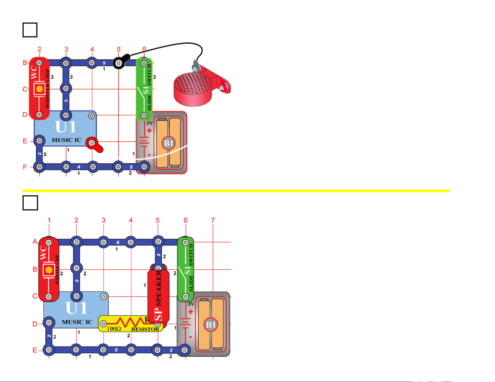
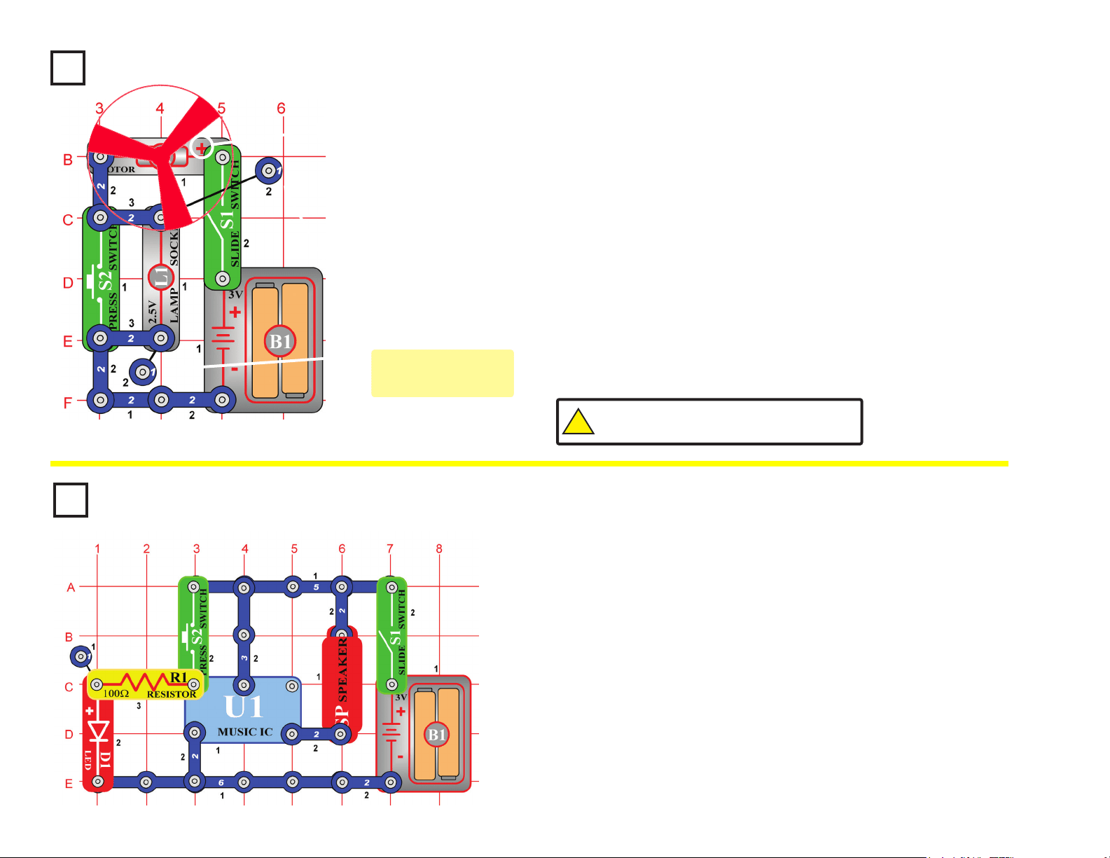
Project #3
Build the circuit shown on the left by placing all the parts with a black 1
next to them on the base grid rst. Then, assemble parts marked with a
2. Finally, lay the speaker (SP) on the table and connect it to the circuit
using the jumper wires as shown.
When you close the slide switch (S1), the music may play for a short
time, and then stop. After the music has stopped, tap on the whistle chip
(WC) and the music should play again. You may also be able to re-start
the sound by clapping loudly next to the whistle chip or by blowing on it.
You could connect the speaker using snap wires instead of the jumper
wires, but then the speaker may create enough sound vibrations to re-
activate the whistle chip.
Sound Activated Switch
OBJECTIVE: To show how sound can turn “ON” an electronic
device.
Project #4
Build the circuit shown on the left. When you close the slide switch (S1),
the music may play for a short time and then stop. After the music has
stopped, tap on the whistle chip (WC) and the music should play again.
You may also be able to re-start the sound by clapping loudly next to
the whistle chip or by blowing on it.
In this project, you changed the amount of current that goes through the
speaker (SP) and reduced the sound output of the speaker. Resistors
are used throughout electronics to limit the amount of current that ows.
Adjusting Sound Level
OBJECTIVE: To show how resistance can lower the sound from
the speaker.
(STANDING)
12
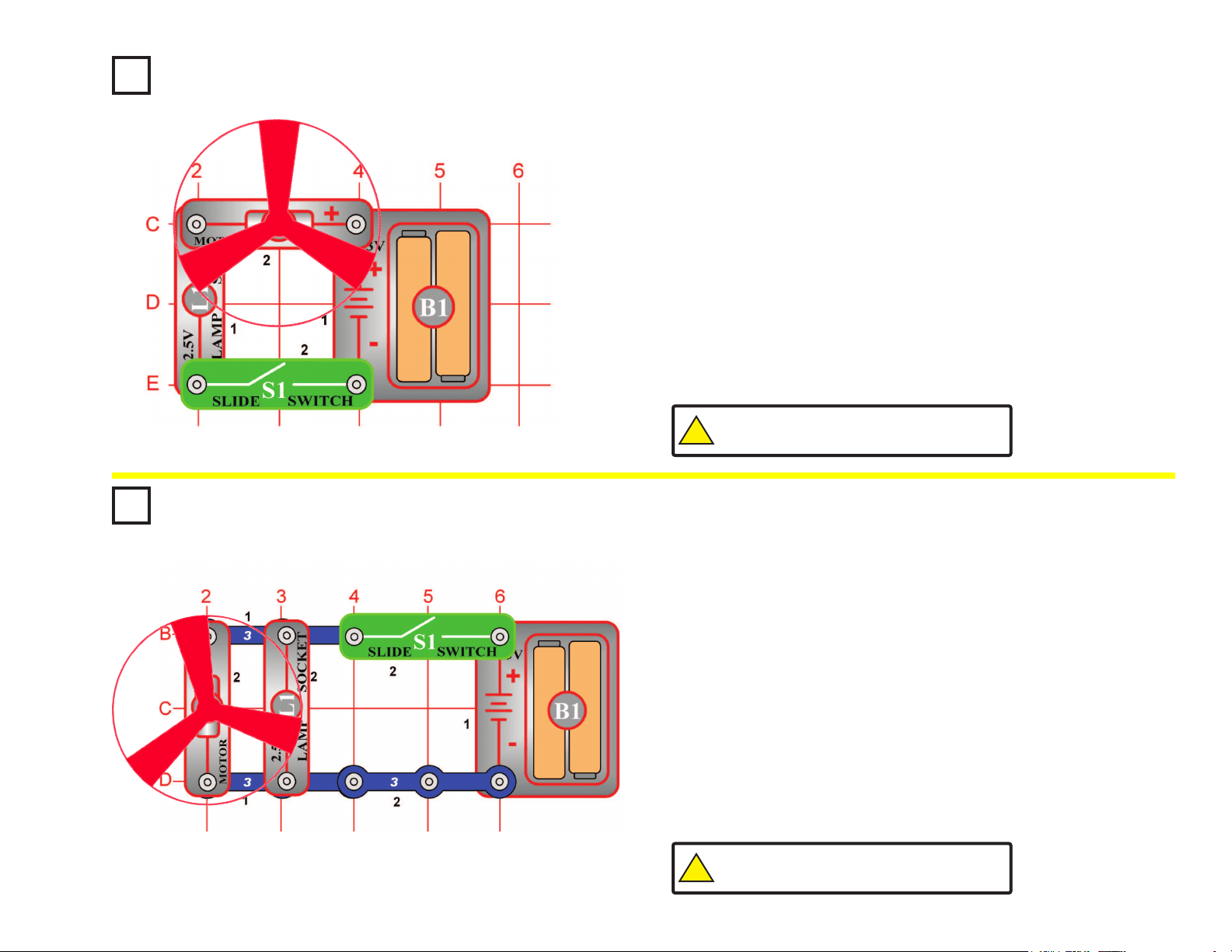
Project #5
Build the circuit shown on the left by placing all the parts with a black 1
next to them on the base grid rst. Then, assemble parts marked with a
2. Finally, place the fan blade on the motor (M1).
When you close the slide switch (S1), the fan will spin and the lamp (L1)
should turn on. The fan will take a while to start turning due to inertia.
Inertia is the property that tries to keep a body at rest from moving and
tries to keep a moving object from stopping.
The light helps protect the motor from getting the full voltage when the
slide switch is closed. Part of the voltage goes across the lamp and the
rest goes across the motor. Remove the fan and notice how the lamp
gets dimmer when the motor does not have to spin the fan blade.
Lamp & Fan in Series
OBJECTIVE: To show how a lamp can indicate when a fan is
running.
Project #6
OBJECTIVE: To show how an indicator light can be connected
without affecting the current in the motor.
Build the circuit shown on the left.
When you close the slide switch (S1), both the fan and the lamp (L1)
should turn on. The fan will take a while to start turning due to inertia.
In this connection, the lamp does not change the current to the motor
(M1). The motor should start a little faster than in Project #5.
Remove the fan and notice how the lamp does not change in brightness
as the motor picks up speed. It has its own path to the battery (B1).
Lamp & Fan in Parallel
!
WARNING: Moving parts. Do not touch the fan or
motor during operation. Do not lean over the motor.
!
WARNING: Moving parts. Do not touch the fan or
motor during operation. Do not lean over the motor.
13
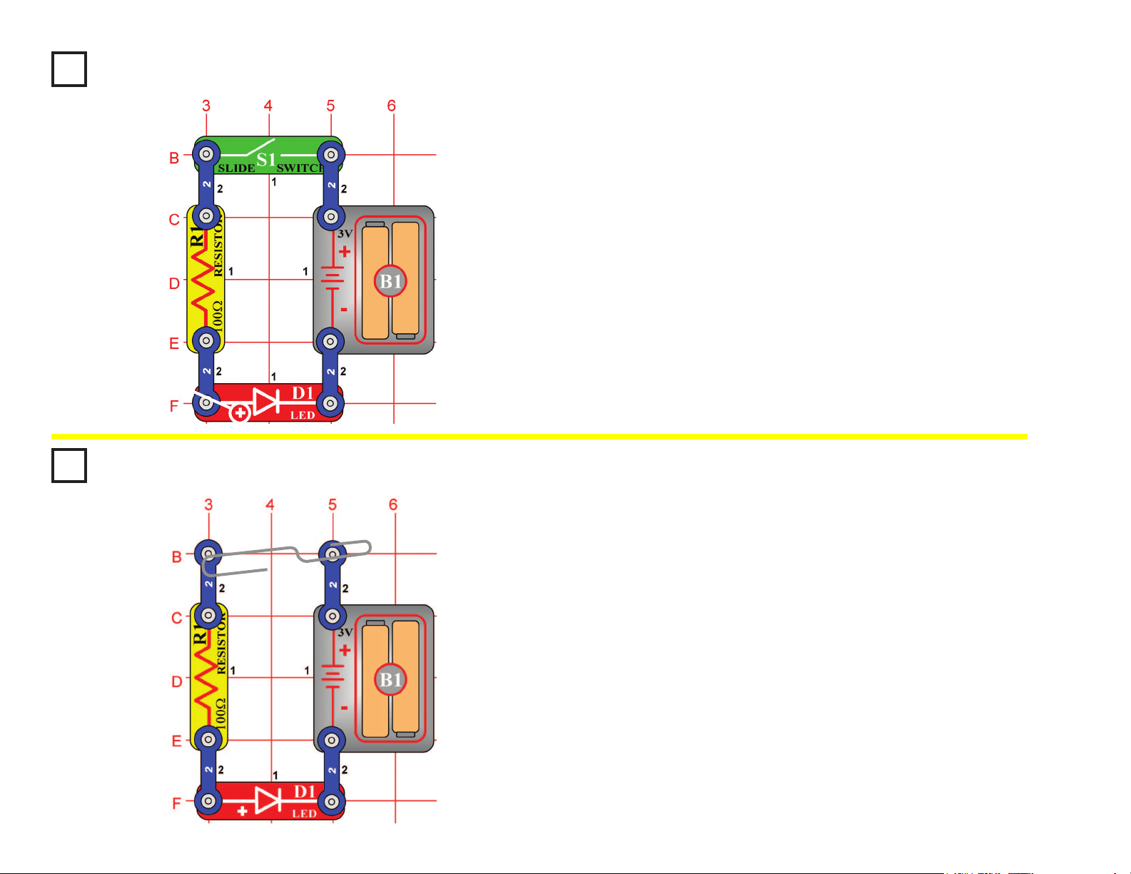
Project #7
Build the circuit shown on the left by placing all the parts with a black 1
next to them on the base grid rst. Then, assemble parts marked with a 2.
When you close the slide switch (S1), current ows from the batteries
(B1) through the slide switch, through the resistor (R1), through the
LED (light emitting diode, D1) and back to the battery. The closed slide
switch completes the circuit. The resistor limits the current and prevents
damage to the LED. NEVER PLACE AN LED DIRECTLY ACROSS THE
BATTERY! If no resistor is in the circuit, the battery may push enough
current through the LED to damage the semiconductor that is used to
produce the light. LEDs are used in all types of electronic equipment to
indicate conditions and pass information to the user of that equipment.
Can you think of something you use everyday that has an LED in it?
Light Emitting Diode
OBJECTIVE: To show how a resistor and LED are wired to
emit light.
+
Project #8
Rebuild the circuit from Project #7 but leave the slide switch (S1) out as
shown on the left.
When you place a metal paper clip across the terminals as shown in
the picture on the left, current ows from the batteries (B1) through the
resistor (R1), through the LED (D1), and back to the battery. The paper
clip completes the circuit and current ows through the LED. Place your
ngers across the terminals and the LED does not light. Your body has
too high of a resistance to allow enough current to ow to light the LED.
If the voltage, which is electrical pressure, was higher, current could be
pushed through your ngers and the LED would light. This detector can
be used to see if a material like plastic is a good conductor or a poor
conductor.
Conduction Detector
OBJECTIVE: To make a circuit that detects the conduction of
electricity in different materials.
14
Project #9
Rebuild the circuit from Project #2, but reverse the polarity on the motor
(M1) so the negative (–) on the motor goes to the positive (+) on the battery
(B1). New alkaline batteries are recommended for this project.
When you close the slide switch (S1), the motor will slowly increase in
speed. When the motor has reached maximum rotation, turn the slide
switch off. The fan blade should rise and oat through the air like a ying
saucer. Be careful not to look directly down on fan blade when it is spinning.
The air is being blown down through the blade and the motor rotation locks
the fan on the shaft. When the motor is turned off, the blade unlocks from
the shaft and is free to act as a propeller and y through the air. If speed of
rotation is too slow, the fan will remain on motor shaft because it does not
have enough lift to propel it. The motor will spin faster when both batteries
are new.
If the fan doesn’t y off, then turn the switch on and off several times rapidly
when it is at full speed.
Flying Saucer
OBJECTIVE: To make a circuit that launches the fan blade to
simulate a ying saucer.
Project #10
OBJECTIVE: To show how voltage affects speed of a DC motor
and can decrease the lift of the saucer.
Change the circuit in Project #9 by adding the lamp (L1) in series with the
motor as shown in the diagram on the left.
When you place the lamp in series with any electronic device, it will draw
less current because it adds resistance. In this case, the lamp in series
reduces the current through the motor, and that reduces the top speed
of the motor. Close the slide switch (S1), and wait until the fan reaches
maximum speed. Open the switch and observe the difference in the
height due to the lamp. In most cases, it may not even launch.
Decreasing Saucer Lift
!
WARNING: Moving parts. Do not touch the fan or
motor during operation. Do not lean over the motor.
!
WARNING: Moving parts. Do not touch the fan or
motor during operation. Do not lean over the motor.
!
WARNING: Fan may not
rise until switch is released.
!
WARNING: Fan may not
rise until switch is released.
+
15
!
WARNING: Moving parts. Do not touch the fan or
motor during operation. Do not lean over the motor.
Project #11
Build the circuit shown on the left by placing all the parts with a black
1 next to them on the board rst. Then, assemble parts marked with a
2. Finally, add the 2-snap wires that are marked for level three.
When you close the slide switch (S1), current ows from the batteries
through the slide switch (S1), motor (M1), the lamp (L1), and back to
the battery (B1). When the press switch (S2) is closed, the lamp is
shorted and motor speed increases.
The principle of removing resistance to increase motor speeds is only
one way of changing the speed of the motor. Commercial fans do not
use this method because it would produce heat in the resistor and
fans are used to cool circuits by moving air over them. Commercial
fans change the amount of voltage that is applied to the motor using a
transformer or other electronic device.
Two-Speed Fan
OBJECTIVE: To show how switches can increase or decrease
the speed of an electric fan.
+
Project #12
Build the circuit shown on the left. When you close the slide switch
(S1), the music integrated circuit (U1) may start playing one song then
stop. Each time you press the press switch “doorbell button” (S2) the
song will play again and stop. Even if you let go of the press switch
(S2), the integrated circuit keeps the song playing until it has reached
the end of the song.
Musical integrated circuits are used to entertain young children
in many of the toys and chairs made to hold infants. If the music
is replaced with words, the child can also learn while they are
entertained. Because of great advances in miniaturization, many songs
are stored in a circuit no bigger than a pinhead.
Musical Doorbell
OBJECTIVE: To show how an integrated circuit can be used as
a musical doorbell.
(STANDING)
These are single
snaps, placed beneath
other parts as spacers
16
Project #13
When you close the slide switch (S1), the music integrated circuit (U1)
may start playing one song then stop. The song will be much louder than
in the previous project because it is now being used as an alarm. Each
time you press the press switch “alarm button” (S2) after the song stops
playing, the song will play again, but only while you hold the button down.
Momentary Alarm
OBJECTIVE: To show how integrated circuits can also create
loud alarm sounds in case of emergencies.
(STANDING)
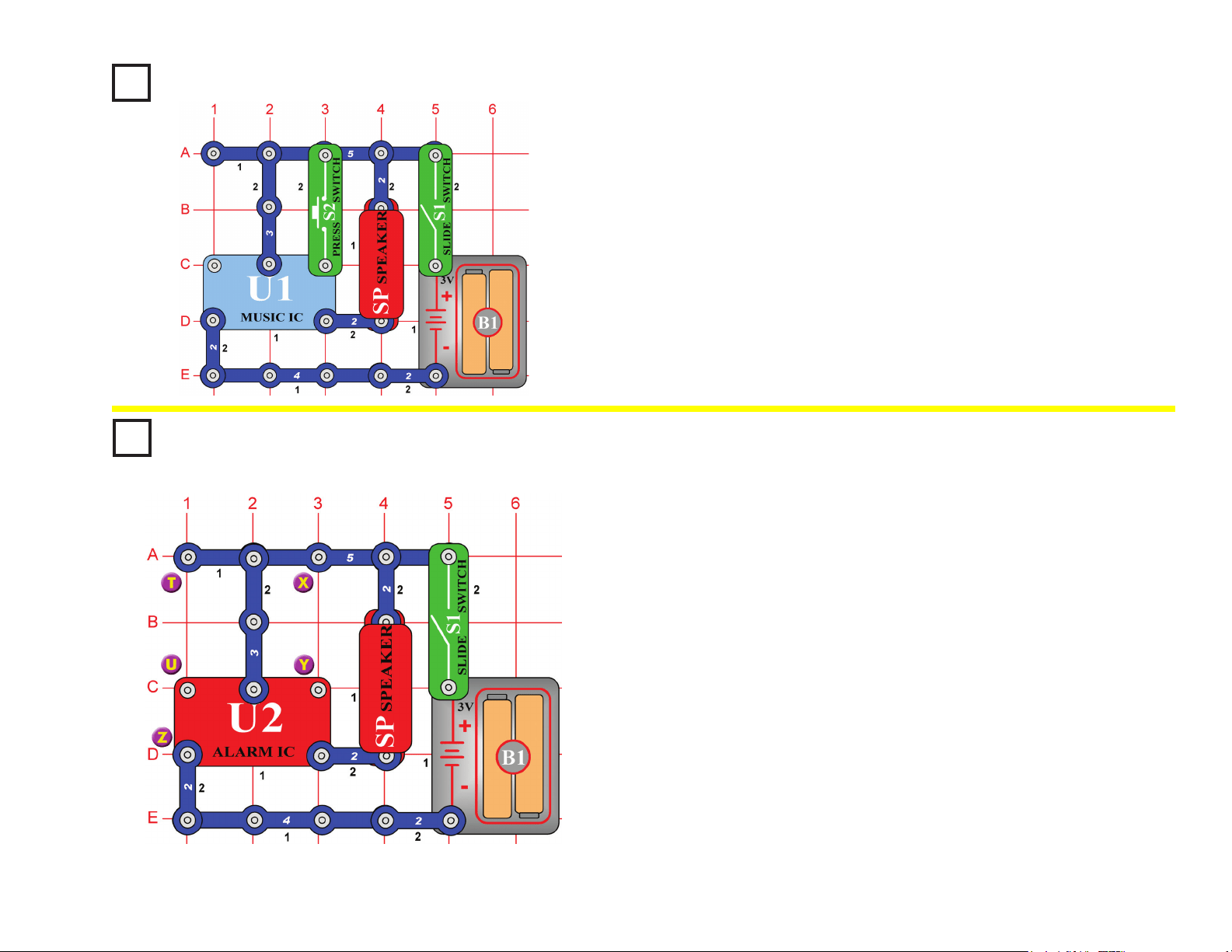
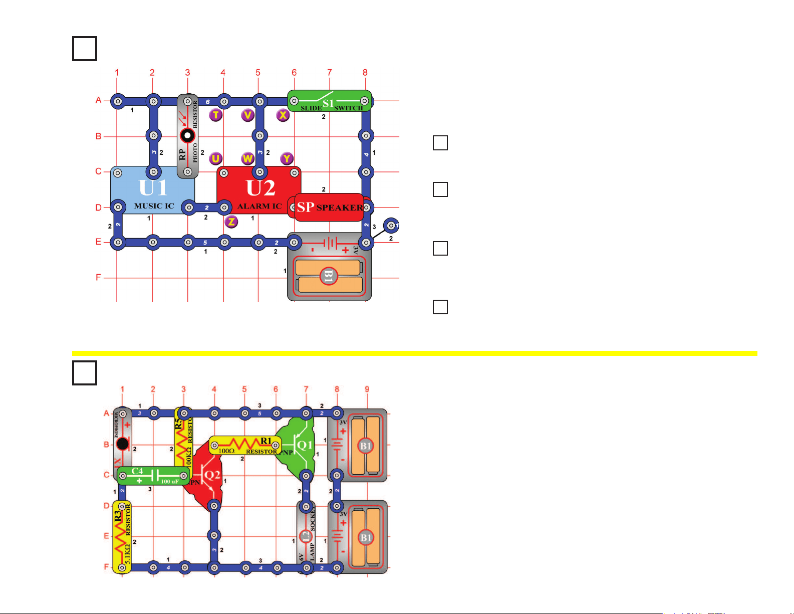
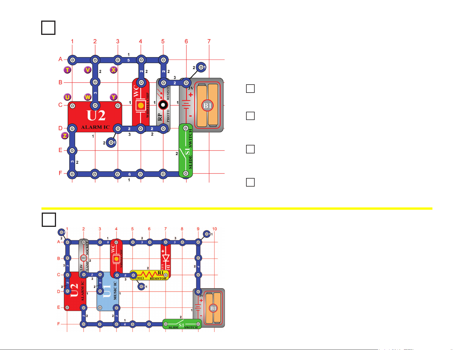
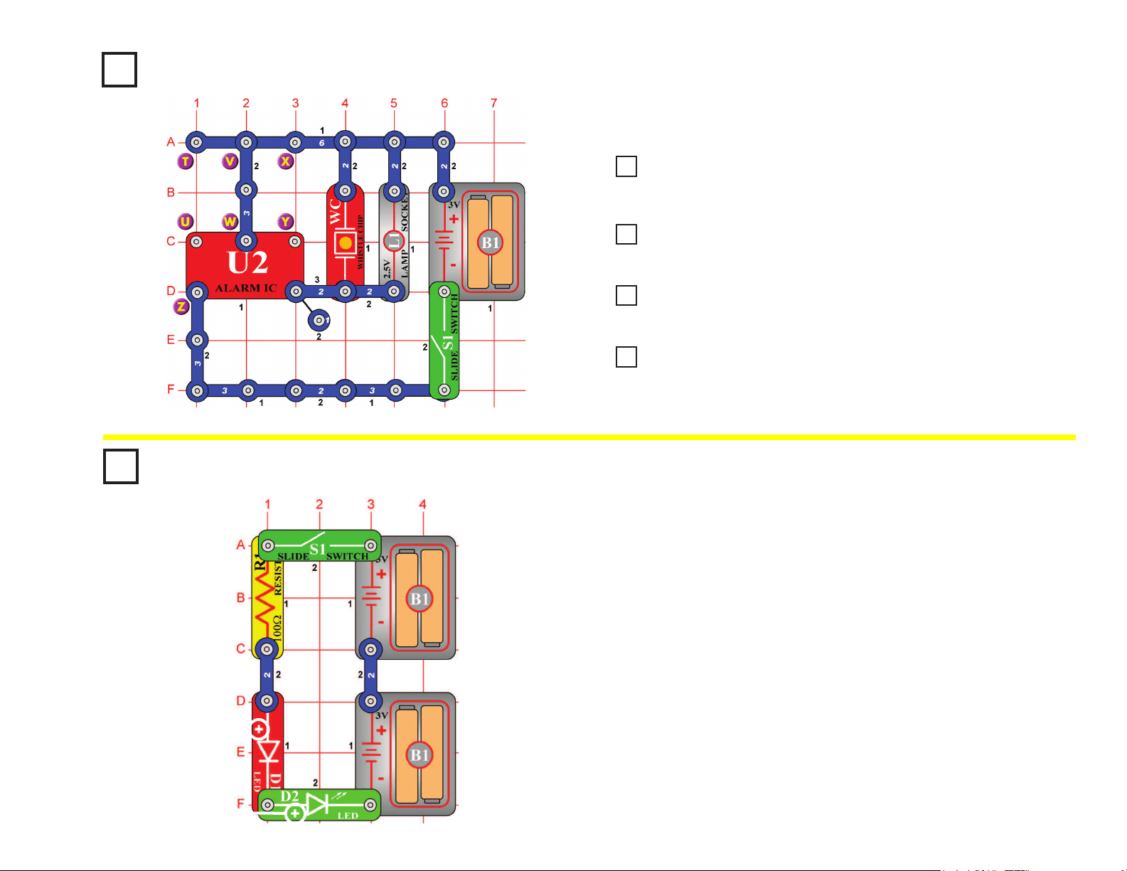
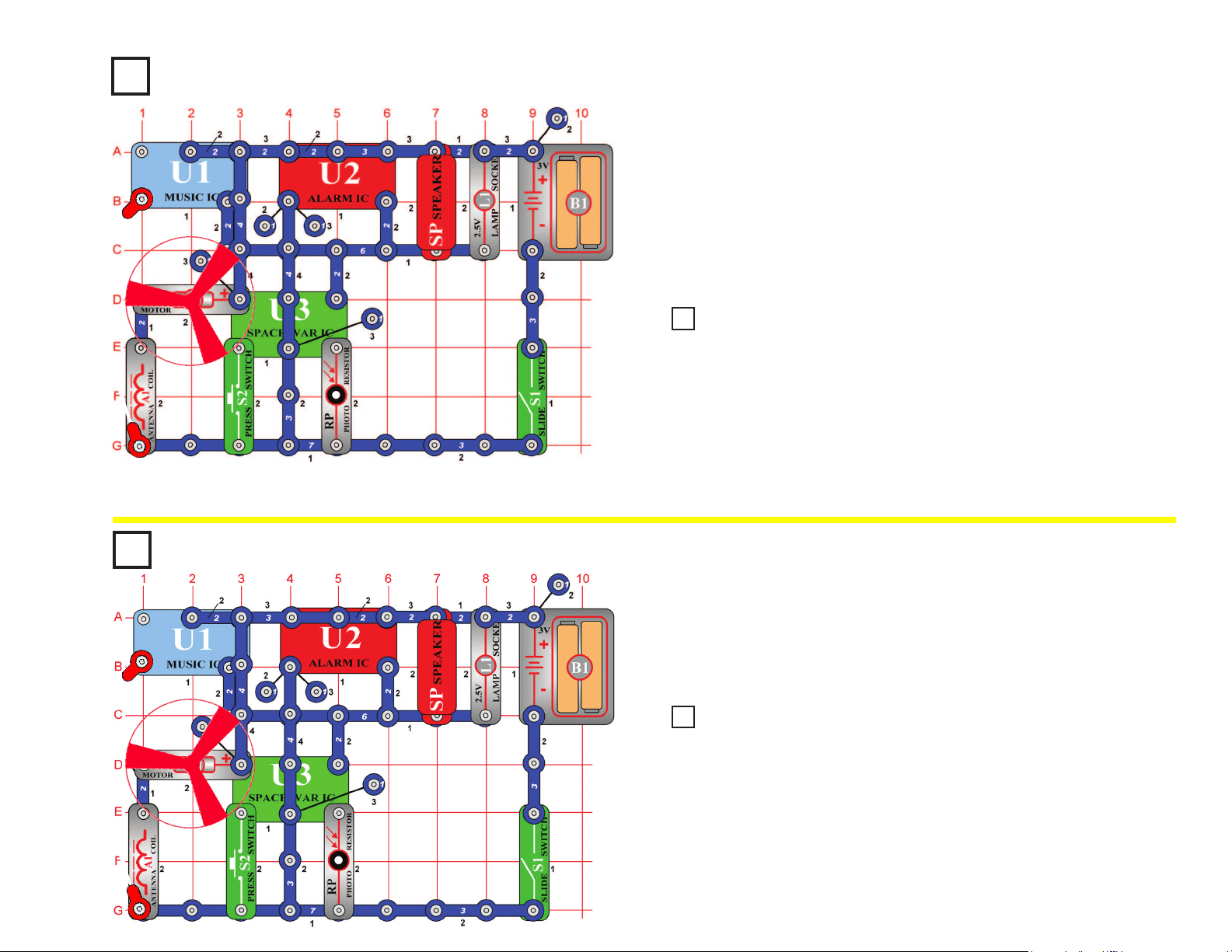
Project #14
Build the circuit shown on the left by placing all the parts with a black 1
next to them on the board rst. Then, assemble parts marked with a 2.
When you close the slide switch (S1), the integrated circuit (U2) should
start sounding a very loud alarm sound. This integrated circuit is
designed to sweep through all the frequencies so even hard of hearing
people can be warned by the alarm.
If the alarm sound was passed through an amplier and installed into a
police car, it would also serve as a good police siren.
Option A: Modify the circuit by connecting points X & Y. The circuit
works the same way but now it sounds like a machine
gun with music.
Option B: Now remove the connection between X & Y and then make
a connection between T & U. The circuit works the same way
but now it sounds like a re engine with music.
Option C: Now remove the connection between T & U and then make
a connection between U & Z. The circuit works the same way
but now it sounds like an ambulance with music.
Alarm Circuit
OBJECTIVE: To show how an integrated circuit can be used to
make real alarm sounds.
(STANDING)
17
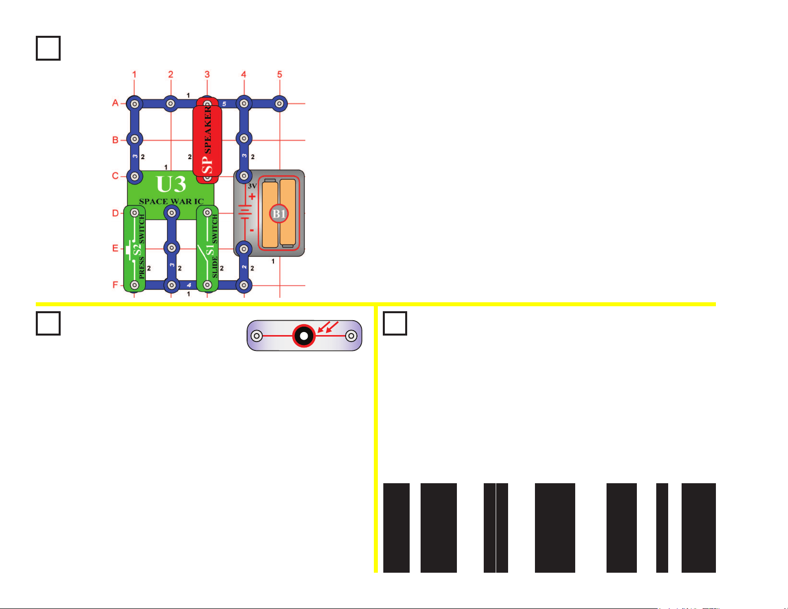
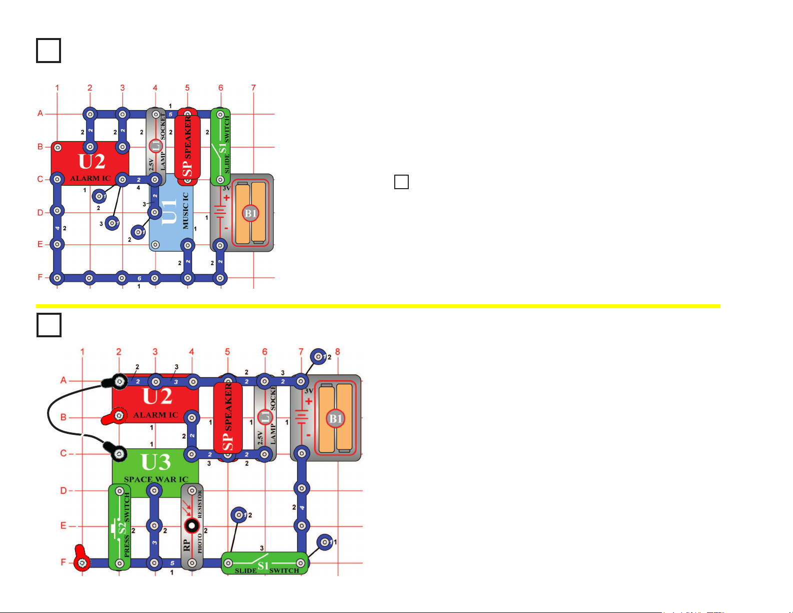
Project #15
Build the circuit shown on the left, which uses the space war integrated
circuit (U3). Activate it by ipping the slide switch (S1) or pressing the
press switch (S2); do both several times and in combination. You will
hear an exciting range of sounds, as if a space war is raging!
Like the other integrated circuits, the space war IC is a super-
miniaturized electronic circuit that can play a variety of cool sounds
stored in it by using just a few extra components.
In movie studios, technicians are paid to insert these sounds at the
precise instant a gun is red. Try making your sound occur at the same
time an object hits the oor. It is not as easy as it sounds.
Space War
OBJECTIVE: To introduce you to the space war integrated
circuit and the sounds it can make.
Project #16
Light Switch
OBJECTIVE: To show how light can control a circuit using
a photoresistor.
Use the circuit from Project #15 above, but replace the slide switch
(S1) with the photoresistor (RP). The circuit immediately makes
noise. Try turning it off. If you experiment, then you can see that
the only ways to turn it off are to cover the photoresistor, or to turn
off the lights in the room (if the room is dark). Since light is used to
turn on the circuit, you might say it is a "light switch".
The photoresistor contains material that changes its resistance
when it is exposed to light. As it gets more light, the resistance of
the photoresistor decreases. Parts like this are used in a number of
ways that affect our lives. For example, you may have streetlights
in your neighborhood that turn on when it starts getting dark and
turn off in the morning.
RP
PHOTO
RESISTOR
Project #17
Paper Space War
OBJECTIVE: To give a more dramatic demonstration of
using the photoresistor.
Use the same circuit as for Project #16. Find a piece of white paper
that has a lot of large black or dark areas on it, and slowly slide it
over the photosensitive resistor. You should hear the sound pattern
constantly changing, as the white and dark areas of the paper
control the light to the photosensitive resistance. You can also try
the pattern below or something similar to it:
(STANDING)
18
Project #18
Cover the photoresistor (RP) and turn on the slide switch (S1). A police
siren with music is heard for a while and stops, then you can control it
by covering or uncovering the photoresistor.
Light Police Siren
OBJECTIVE: To build a police siren that is controlled by light.
(STANDING)
Project #19 More Loud Sounds
Project #20 More Loud Sounds (II)
Project #21 More Loud Sounds (III)
Project #22 More Loud Sounds (IV)
Modify the Project #18 by connecting points X & Y. The circuit works the
same way but now it sounds like a machine gun with music.
Now remove the connection between X & Y and then make a connection
between T & U. The circuit works the same way but now it sounds like a
re engine with music.
Now remove the connection between T & U and then make a connection
between U & Z. The circuit works the same way but now it sounds like an
ambulance with music.
Now remove the connections between U & Z and between V & W, then
make a connection between T & U. The circuit works the same way but
now it sounds like a familiar song but with static.
Blowing Off the
Electric Light
OBJECTIVE: To show how light is stimulated by sound.
Install the parts. The lamp (L2) will be on. It will be off as long as
you blow on the mic (X1). Speaking loud into the mic will change the
brightness of the lamp.
Project #23
19
Build the circuit shown on the left and turn it on. The lamp (L1)
alternates between being on and off while the speaker (SP)
alternates between two musical tones... like someone is ipping a
switch, but at a very consistent rate. Periodic signals like this are very
important in electronics. The lamp may not be very bright.
Periodic Sounds
OBJECTIVE: To build a circuit with light and sound that
change and repeat.
(STANDING)
Project #24
Project #25 Blinking Double Flashlight
OBJECTIVE: To build a circuit with two lights that alternate.
In the circuit at left, replace the speaker (SP) with the color LED (D8, “+” on top).
The lamp alternates between being on and off while the LED alternates between
being dimmer and brighter.
Project #26
Build the circuit shown and add the jumpers to complete it. Turn it on,
press the press switch (S2) several times, and wave your hand over the
photoresistor (RP) to hear all the sound combinations. If the sound is
too loud you may replace the speaker (SP) with the whistle chip (WC).
Space War Alarm Combo
OBJECTIVE: To combine the sounds from the space war and
alarm integrated circuits.
(STANDING)
20
Project #27
This circuit is controlled by spinning the motor (M1) with your hands.
Turn on the slide switch (S1). A police siren is heard and then stops.
Spin the motor and it will play again. Note however, that music can be
heard faintly in the background of the siren.
Motor-Controlled Sounds
OBJECTIVE: To show how motion can trigger electronic circuits.
(STANDING)
Project #28 More Motor Sounds
Project #29 More Motor Sounds (II)
Project #30 More Motor Sounds (III)
Project #31 More Motor Sounds (IV)
Modify the last circuit by connecting points X & Y with the lamp (L1). The
circuit works the same way but now it sounds like a machine gun.
Now remove the connection between X & Y and then make a connection
between T & U with the lamp (L1). The circuit works the same way but now it
sounds like a re engine.
Now remove the connection between T & U and then make a connection
between U & Z. The circuit works the same way but now it sounds like an
ambulance.
Now remove the connections between U & Z and between V & W, then make
a connection between T & U. The circuit works the same way but now it
sounds like a familiar song but with static.
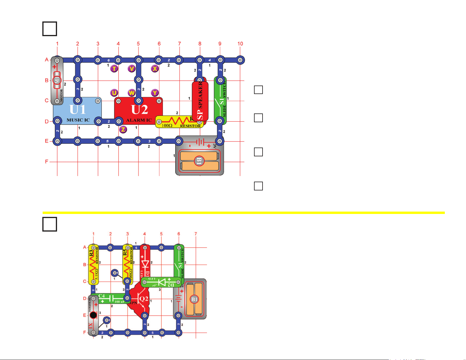
Voice-controlled Rays
of Light
OBJECTIVE: To show how light is stimulated by sound.
Turn the slide switch (S1) on. There will be only a weak light emitting
from the green LED (D2). By blowing on the mic (X1) or putting it near
a radio or TV set, the green LED will emit light, and its brightness
changes as the loudness changes.
Project #32
21
Turn on the slide switch (S1) and tap the whistle chip (WC), it makes a machine
gun sound (with music in the background). Thoroughly cover the photoresistor
(RP) with your hand and the sound becomes a siren. After a while the sound will
stop, tap the whistle chip and it resumes.
Press the press switch (S2) and the LED (D1) lights, but the lamp (L1) does not
light and the motor (M1) does not spin. Electricity is owing through the lamp
and motor, but not enough to turn them on. So in this circuit they are acting like
3-snap wires.
Project #33
Using Parts as Conductors
OBJECTIVE: To show that motors and lamps may sometimes be used as
ordinary conductors.
(STANDING)
Project #34
Setup: Cut out a circular piece of thin cardboard from the back of an old spiral
notebook or note pad. Use the fan blade as a guide. Place the fan on the
cardboard and trace around it with a pencil or pen. Cut the cardboard out with
scissors and tape it to the fan blade. Do the same thing with a piece of white
paper, but tape the paper on top of the cardboard so it can be removed easily later.
Drawing: To make a ring drawing obtain some thin and thick marking pens as
drawing tools. Spin the paper by pressing and holding press switch (S2) down.
Press the marker on the paper to form rings. To make spiral drawings, release
press switch and as the motor (M1) approaches a slow speed move the marker
from the inside outward quickly.
Change the colors often and avoid using too much black to get hypnotic effects.
Another method is to make colorful shapes on the disc then spin the disc and
watch them blend into each other. When certain speeds are reached under
uorescent lights without electronic ballasts, the strobe principle shown in another
project will produce strange effects and backward movement. Make a wheel
with different colored spokes to see this strange effect. Adding more spokes and
removing spokes will give different effects at different motor speeds.
Spin Draw
OBJECTIVE: To produce circular artistic drawings.
Thin Cardboard White Paper
22
Project #35
Turn on the slide switch (S1), a police siren is hear. The loudness of the
sound depends on how much light reaches the photoresistor (RP), try partially
shielding it or placing near a very bright light, and compare the sound.
Light-Controlled Sounds
OBJECTIVE: To give a more dramatic demonstration of using
the photosensitive resistance.
Project #36
Light-Controlled Sounds (II)
Project #37
Light-Controlled Sounds (III)
Project #38
Light-Controlled Sounds (IV)
Project #39
Light-Controlled Sounds (V)
Modify the last circuit by connecting points X & Y. The circuit works the
same way but now it sounds like a machine gun.
Now remove the connection between X & Y and then make a connection
between T & U. The circuit works the same way but now it sounds like a re
engine.
Now remove the connection between T & U and then make a connection
between U & Z. The circuit works the same way but now it sounds like an
ambulance.
Now remove the connection between U & Z, add a 1-snap at Z (on level 3),
add a second 3-snap between V & W (on level 3), and nally place the music
IC (U1) directly over the alarm IC (U2) on level 4. Listen to the sounds.
Project #40
Turn the slide switch (S1) on and the lamp (L1) and LED (D1) start
ashing. You hear two different tones driving the LED and lamp. ICs can
be connected to control many different devices at the same time.
Flash and Tone
OBJECTIVE: Build a circuit that ashes light and plays sounds.
23
Project #41
Build the circuit shown and place the fan on the motor (M1), but leave the
jumpers off for the time being. Turn on the slide switch (S1) and tap the whistle
chip (WC), it makes a machine gun sound (with music in the background).
Thoroughly cover the photoresistor (RP) with your hand and the sound
becomes a siren. With the photoresistor covered, press the press switch (S2)
and the sound becomes that of an ambulance. Uncover the photoresistor and
the sound remains that of a machine gun whether the press switch is pressed
or not. After a while the sound will stop, tap the whistle chip and it resumes.
Connect the two jumpers as shown and tap the whistle chip to resume the
sound. The lamp (L1) and LED (D1) light and the motor spins. The sound
continues, but it may become distorted as the motor speeds up. The motor
draws a lot of power from the batteries (B1), and this may reduce the voltage
to the music (U1) and alarm (U2) ICs, distorting the sound. The sound may
even stop if your batteries are weak.
Fun with the Alarm IC
OBJECTIVE: To show some new ways of using the alarm IC.
Project #42 Project 43
Motor
Sounds
Combo
OBJECTIVE: To connect
multiple devices together.
Motor
Sounds
Combo (II)
OBJECTIVE: To connect
multiple devices together.
In the circuit, the outputs from
the alarm and music ICs are
connected together. Build the
circuit shown and then place the
alarm IC (U2) directly over the
music IC (U1), resting on two
1-snaps and a 2-snap. Turn on
the slide switch (S1) and you will
hear a siren and music together
while the lamp (L1) varies in
brightness. Push the press switch
(S2) and the fan spins, while the
sound may not be as loud. The
fan may rise into the air when you
release the press switch.
In the circuit, the outputs from the alarm
and music ICs are connected together.
Build the circuit shown and then place the
alarm IC (U2) directly over the music IC
(U1), resting on three 1-snaps. Turn on the
slide switch (S1) and you will hear a siren
and music together. Push the press switch
(S2) and the fan spins, while the sound
may not be as loud. The fan may rise into
the air when you release the switch.
This circuit is similar to project #42, but the
fan will y a little higher since the sound
circuit no longer drives the lamp (L1) and
therefore uses less battery power.
(STANDING)
!
WARNING: Moving parts. Do not touch the fan or
motor during operation. Do not lean over the motor.
(STANDING)
(STANDING)
+
+
24
In the circuit, the outputs from the alarm and music ICs are connected
together. Build the circuit shown and then place the alarm IC (U2) directly
over the music IC (U1), resting on two 1-snaps and a 2-snap. There is
also a 2-snap on top of the alarm IC. Turn on the switch (S1) and you will
hear a siren and music together while the lamp (L1) varies in brightness.
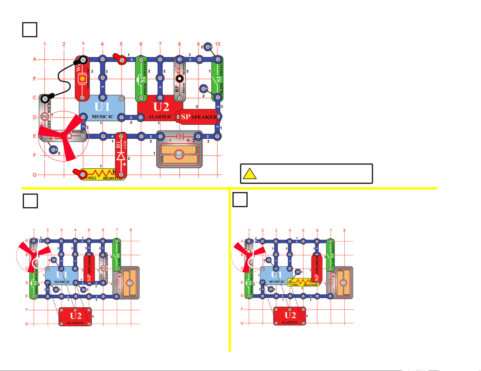
Project #46
Wacky Sounds
OBJECTIVE: To combine different sounds.
Build the circuit shown. Turn it on, press the press switch (S2) several
times, and wave your hand over the photoresistor to hear all the sound
combinations. You can make the sound from the music IC louder by
replacing the 100W resistor (R1) with the lamp (L1).
Really Wacky Sounds
OBJECTIVE: To combine different sounds.
Project #44
(STANDING)
(STANDING)
Project #45
Wackier Sounds
Now remove the 2-snap connection between X & Y and then make a
2-snap connection between X & Z (on level 5). The circuit works the same
way but has different sounds.
25
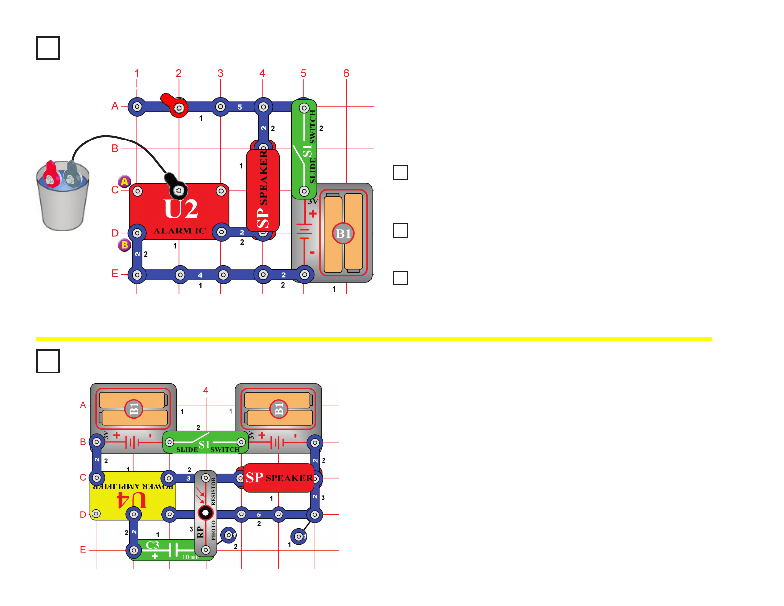
Build the circuit shown but initially leave the jumper wires outside the
cup. Turn on the slide switch (S1); nothing happens. Place the jumper
wires into a cup of water and an alarm sounds!
You could use longer wires and lay them on your basement oor, if your
basement oods during a storm, then this circuit will sound an alarm.
Project #47 Simple Water Alarm
OBJECTIVE: To sound an alarm when water is detected.
(STANDING)
Project #48
Simple Salt Water Alarm
Project #49
Ambulance Water Alarm
Project #50
Ambulance Contact Alarm
Add salt to the water and the tone of the alarm is louder and faster, telling
you that salt is in the water you detected. Also, try holding the jumper
wires with your ngers to see if your body can set off the alarm.
Modify the circuit in Project #47 by making a connection between A & B.
The water alarm works the same way but now it sounds like an ambulance.
The same circuit also detects if the jumper wires get touched together, so
connect them to each other. The tone of the sound is now much different.
Therefore, this circuit will tell you if there is water between the jumper
wires or if the wires are touching each other.
Project #51
Build the circuit as shown, and turn on the slide switch (S1). Vary the
amount of light to the photoresistor (RP) by partially covering it with your
hand. You can make screeching sounds by allowing just a little light to
reach the photoresistor.
If you replace the 10mF capacitor (C3) with a 3-snap wire or any of
the other capacitors (C1, C2, C4, or C5), then the sound will be a little
different.
Ticking Screecher
OBJECTIVE: To make fun sounds using light.
26
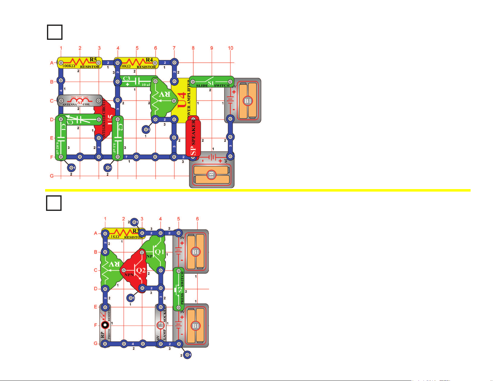
Project #52
When you turn on the slide switch (S1), the integrated circuit (U5)
should amplify and detect the AM radio waves all around you. The
variable capacitor (CV) can be tuned to the desirable station. Varying
the adjustable resistor (RV) will make the audio louder or softer. The
power amplier IC (U4) drives the speaker (SP) to complete the AM
radio project.
AM Radio
OBJECTIVE: To make a complete working AM radio.
Project #53
Press the press switch (S2) on and set the adjustable resistor (RV) so
the lamp (L2) just lights. Slowly cover the photoresistor (RP) and the
lamp brightens. If you place more light at the photoresistor the light dims.
This is an automatic street lamp that you can turn on by a certain
darkness and turn off by a certain brightness. This type of circuit is
installed on many outside lights and forces them to turn off and save
electricity. They also come on when needed for safety.
Automatic Street Lamp
OBJECTIVE: To show how light is used to control a street lamp.
27
Project #54
Turn on the slide switch (S1); the speaker (SP) will sound and the LED
(D1) will light. Adjust the adjustable resistor (RV) to make different
tones. In an oscillator circuit, changing the values of resistors or
capacitors can vary the output tone or pitch.
Adjustable Tone
Generator
OBJECTIVE: To show how resistor values change the
frequency of an oscillator.
Project #55
Photosensitive
Electronic Organ
OBJECTIVE: To show how resistor values change the
frequency of an oscillator.
Project #56
Electronic Cicada
OBJECTIVE: To show how capacitors in parallel change
the frequency of an oscillator.
Use the circuit from project #54 shown above. Replace the
10kΩ resistor (R4) with the photoresistor (RP). Turn on the slide
switch (S1). The speaker (SP) will sound and the LED (D1) will
light. Move your hand up and down over the photoresistor and
the frequency changes. Decreasing the light on the photoresistor
increases the resistance and causes the circuit to oscillate at a
lower frequency. Notice that the LED ashes also at the same
frequency as the sound.
By using your nger, see if you can vary the sounds enough to
make this circuit sound like an organ playing.
Use the circuit from project #54 shown above, replace the
photoresistor (RP) back to the 10kΩ resistor (R4). Place the
0.02μF capacitor (C1) on top of the whistle chip (WC). Place the
slide switch (S1) on and adjust the adjustable resistor (RV). The
circuit produces the sound of the cicada insect. By placing the
0.02μF capacitor on top of the whistle chip, the circuit oscillates
at a lower frequency. Notice that the LED (D1) ashes also at the
same frequency.
It is possible to pick resistors and capacitors that will make the
pitch higher than humans can hear. Many animals, however, can
hear these tones. For example, a parakeet can hear tones up to
50,000 cycles per second, but a human can only hear to 20,000.
28
Turn on the slide switch (S1). A police siren is heard and the lamp (L1) lights.
Project #57
Light & Sounds
OBJECTIVE: To build a police siren with light.
Project #58
More Light & Sounds
Project #59
More Light & Sounds (III)
Project #60
More Light & Sounds (IV)
Project #61
More Light & Sounds (V)
Modify the last circuit by connecting points X & Y. The circuit works the
same way but now it sounds like a machine gun.
Now remove the connection between X & Y and then make a connection
between T & U. Now it sounds like a re engine.
Now remove the connection between T & U and then make a connection
between U & Z. Now it sounds like an ambulance.
Now remove the connection between U & Z, then place the 470μF capacitor
(C5) between X & Y (“+” side to X). The sound changes after a few seconds.
Project #62
When you turn on the slide switch (S1), current ows from the batteries
through the slide switch, the 100W resistor (R1), the LED (D1), through
the LED (D2), and back to the second group of batteries (B1). Notice
how both LEDs are lit. The voltage is high enough to turn on both
LEDs when the batteries are connected in series. If only one set of
batteries is used, the LEDs will not light up.
Some devices use only one 1.5 volt battery, but they make hundreds of
volts electronically from this small source. A ash camera is an example
of this.
Batteries in Series
OBJECTIVE: To show the increase in voltage when batteries
are connected in series.
+
+
29
Project #63
When building the circuit, be sure to position the motor (M1) with the
positive (+) side snapped to the 470mF capacitor (C5). Turn on the slide
switch (S1), nothing will happen. It is a motor speed detector, and the
motor isn’t moving. Watch the LED (D2) and give the motor a good spin
CLOCKWISE with your ngers (don’t use the fan blade); you should
see a ash of light. The faster you spin the motor, the brighter the ash
will be. As a game, see who can make the brightest ash.
Now try spinning the motor in the opposite direction (counter-clockwise)
and see how bright the ash is — it won’t ash at all because the
electricity it produces, ows in the wrong direction and won’t activate
the diode. Flip the motor around (positive (+) side snapped to the
3-snap wire) and try again. Now the LED lights only if you spin the
motor counter-clockwise.
Motor Speed Detector
OBJECTIVE: To show how to make electricity in one direction.
Project #64
Turn on the slide switch (S1), nothing will happen. Turn the motor
(M1) slowly with your ngers (don’t use the fan blade), you will hear a
clicking that sounds like an old-time manual typewriter keystrokes. Spin
the motor faster and the clicking speeds up accordingly.
This circuit works the same if you spin the motor in either direction
(unlike the Motor Speed Detector project).
By spinning the motor with your ngers, the physical effort you exert
is converted into electricity. In electric power plants, steam is used to
spin large motors like this, and the electricity produced is used to run
everything in your town.
Old-Style Typewriter
OBJECTIVE: To show how a generator works.
30
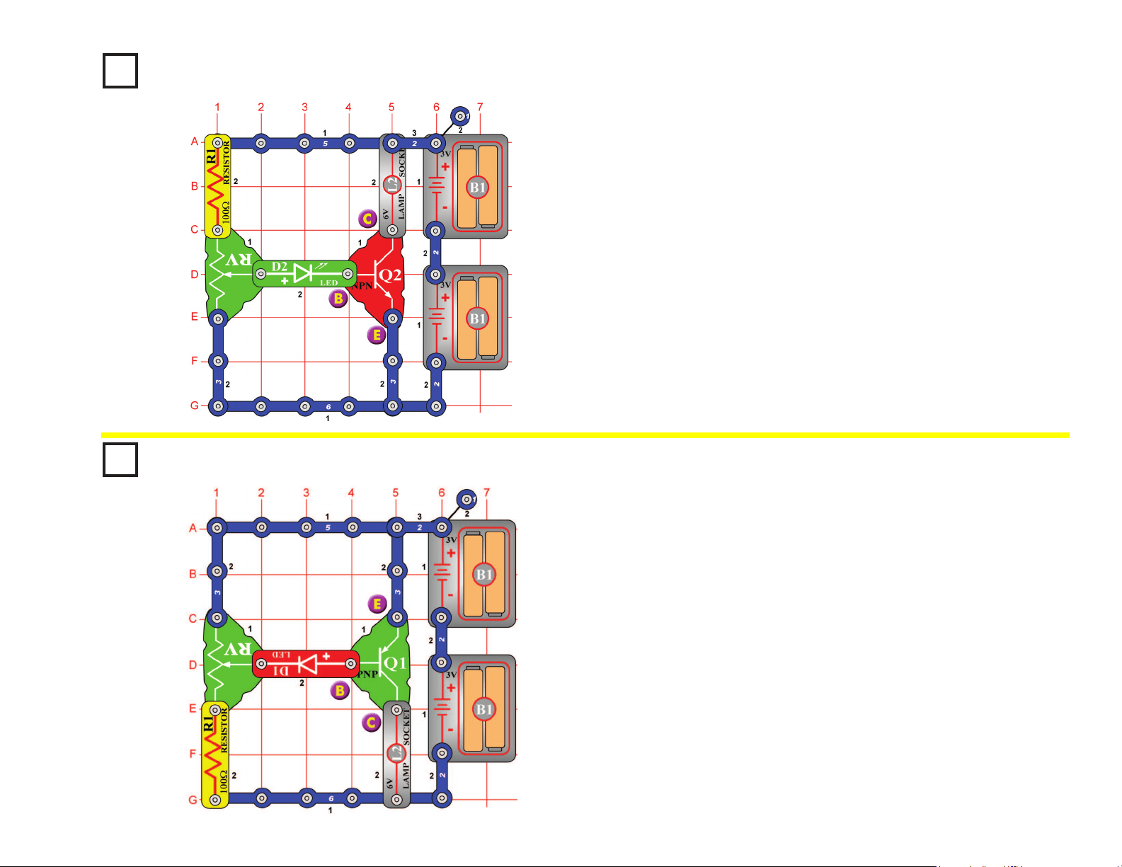
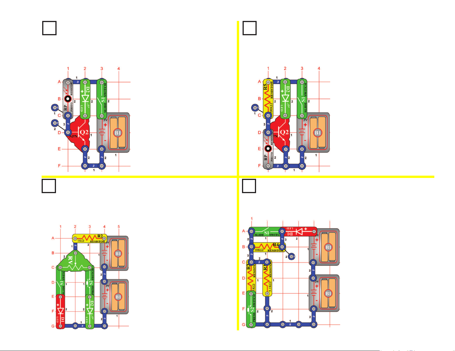
Project #65
There are three connection points on an NPN transistor (Q2), called
base (marked B), emitter (marked E), and collector (marked C). When
a small electric current ows from the base to the emitter, a larger
(amplied) current will ow from the collector to the emitter. Build the
circuit and slowly move up the adjustable resistor (RV) control. When
the LED (D2) becomes bright, the lamp (L2) will also turn on and will be
much brighter.
NPN Amplier
OBJECTIVE: To compare transistor circuits.
Project #66
The PNP transistor (Q1) is similar to the NPN transistor (Q2) in project
#65, except that the electric currents ow in the opposite directions.
When a small electric current ows from the emitter to the base, a
larger (amplied) current will ow from the emitter to the collector. Build
the circuit and slowly move up the adjustable resistor (RV) control.
When the LED (D1) becomes bright, the lamp (L2) will also turn on and
will be much brighter.
PNP Amplier
OBJECTIVE: To compare transistor circuits.
31
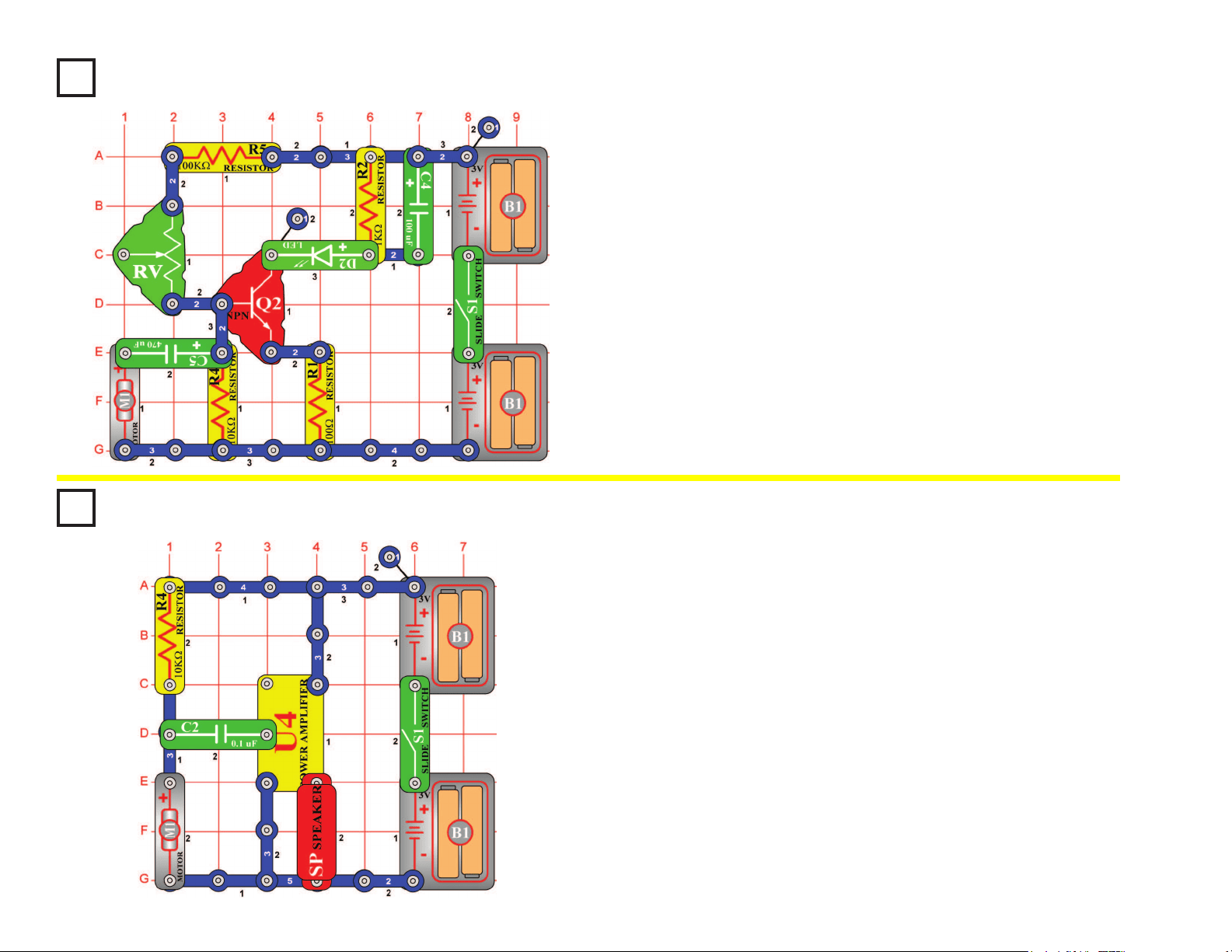
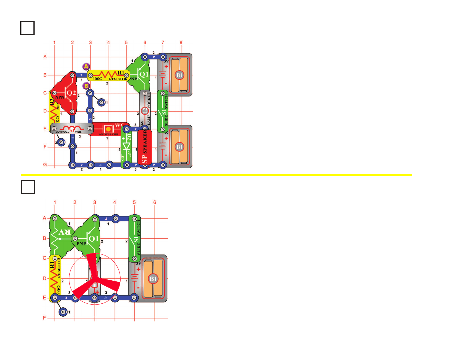
Sucking Fan
OBJECTIVE: To adjust the speed of a fan.
Build the circuit, and be sure to orient the motor (M1) with the positive (+)
side down as shown. Turn it on, and set the adjustable resistor (RV) for
the fan speed you like best. If you set the speed too fast then the fan may
y off the motor. Due to the shape of the fan blades and the direction the
motor spins, air is sucked into the fan and towards the motor. Try holding
a piece of paper just above the fan to prove this. If this suction is strong
enough then it can lift the fan blades, just like in a helicopter.
The fan will not move on most settings of the resistor, because the
resistance is too high to overcome friction in the motor. If the fan does not
move at any resistor setting, then replace your batteries.
Modify the circuit by reversing the position of the motor (M1), so the
positive (+) side is towards the PNP (Q1). Turn it on, and set the
adjustable resistor (RV) for the fan speed you like best. Set it for full
speed and see if the fan ies off - it won’t! The fan is blowing air upward
now! Try holding a piece of paper just above the fan to prove this.
Project #68
Project #67
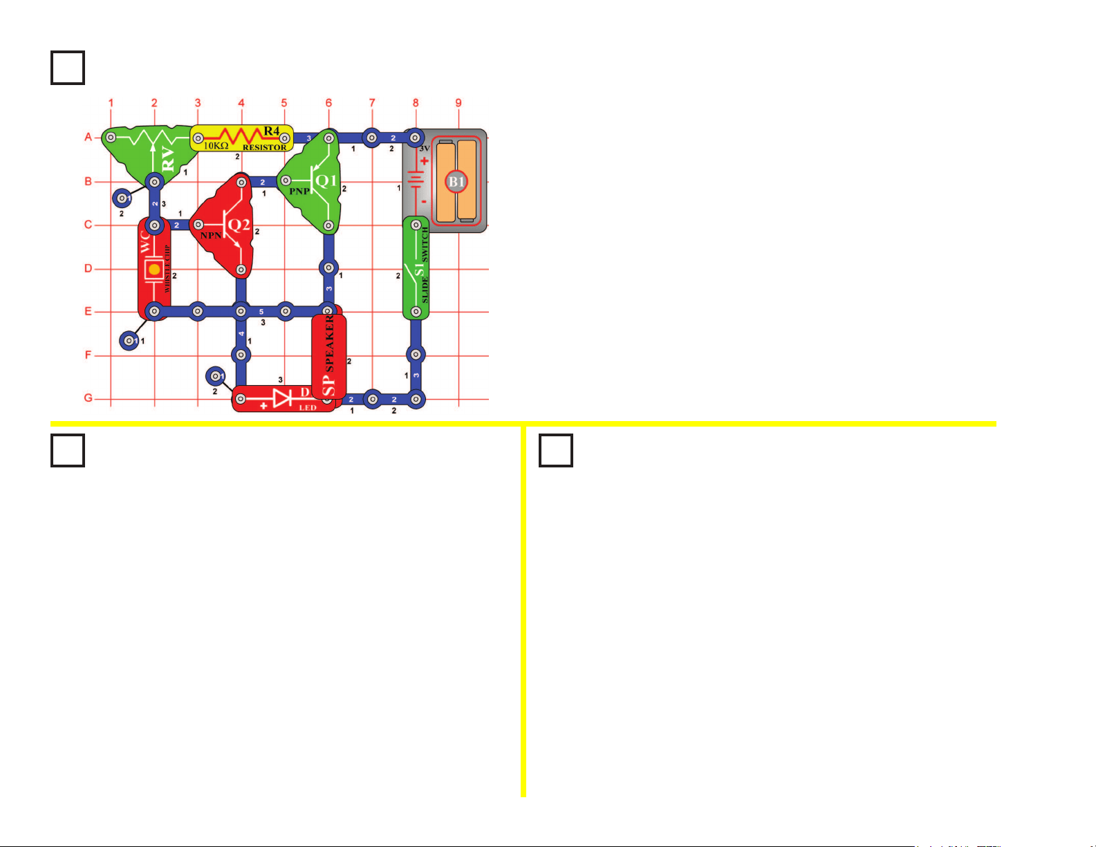
Turn on the slide switch (S1) and place your nger across points A & B.
The speaker (SP) will output a tone and the LED (D2) will ash at the
same frequency. Your nger acts as a conductor connecting points A &
B. When a person is lying, one thing the body starts to do is sweat. The
sweat makes the nger a better conductor by reducing its resistance.
As the resistance drops, the frequency of the tone increases. Lightly
wet your nger and place it across the two points again. Both the output
tone and LED ashing frequency increase, and the lamp (L2) may begin
to light. If your nger is wet enough, then the lamp will be bright and
the sound stops - indicating you are a big liar! Now change the wetness
of your nger by drying it and see how it affects the circuit. This is the
same principle used in lie detectors that are sold commercially.
The Lie Detector
OBJECTIVE: To show how sweat makes a better conductor.
32
+
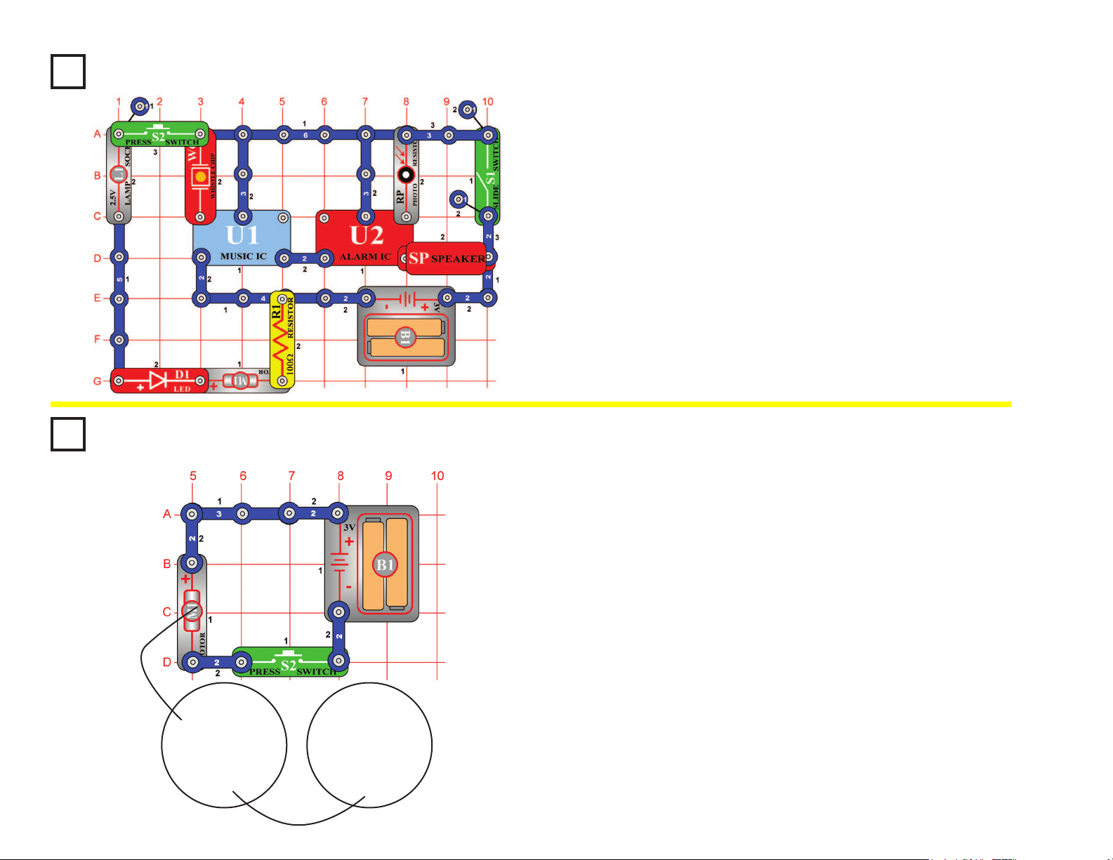
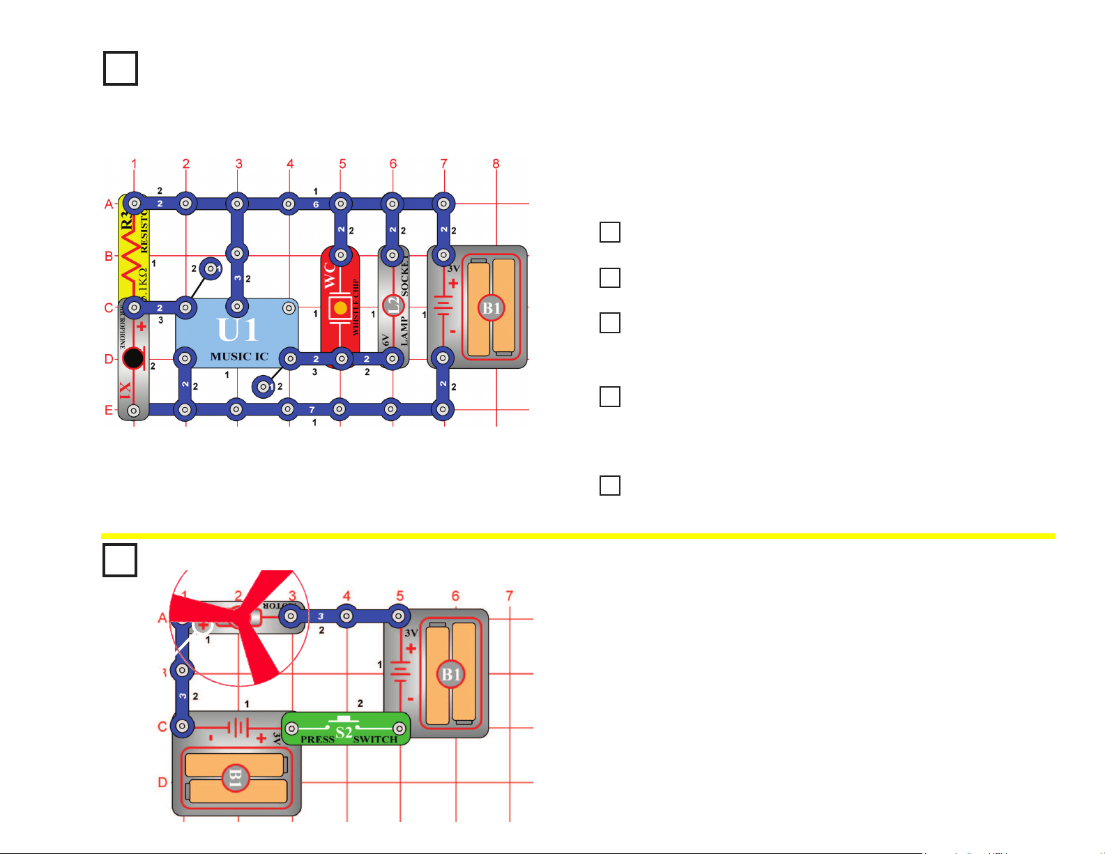
Project #69
High Sensitivity Voice
Doorbell
OBJECTIVE: To build a highly sensitive voice-activated doorbell.
Build the circuit and wait until the sound stops. Clap or talk loud a few
feet away and the music plays again. The microphone (X1) is used here
because it is very sensitive.
Project #71
Very Loud Doorbell
Project #72
Doorbell with Button
Project #73
Darkness Announcer
Project #74
Musical Motion Detector
Replace the 6V lamp (L2) with the antenna coil (A1), the sound is louder now.
Replace the antenna coil (A1) with the speaker (SP), the sound is now louder.
Replace the microphone (X1) with the press switch (S2) and wait until the
music stops. Now you have to push the press the switch to activate the
music, just like the doorbell on your house.
Replace the press switch (S2) with the photoresistor (RP) and wait until the
sound stops. If you cover the photoresistor now the music will play once,
signaling that it has gotten dark. If the speaker (SP) is too loud then you may
replace it with the antenna coil (A1).
Replace the photoresistor (RP) with the motor (M1), oriented in either
direction. Now spinning the motor will re-activate the music.
Project #70
Louder Doorbell
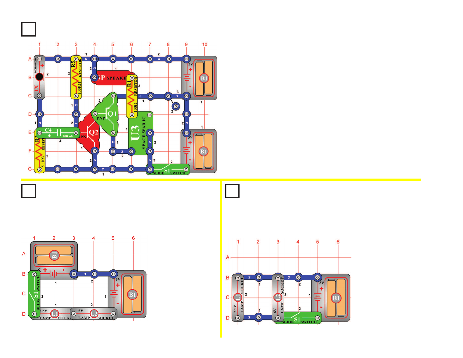
Project #75
This circuit will make the fan spin faster and y higher than the
preceding circuit, making it easy to lose your fan.
Push the press switch (S2) until the motor reaches full speed, then
release it. The fan blade should rise and oat through the air like a
ying saucer. Be careful not to look directly down on fan blade when it
is spinning.
Super Flying Saucer
OBJECTIVE: To make the fan blade y.
33
Project #76
Blow Off a Space War
OBJECTIVE: To turn off a circuit by blowing on it.
Project #77
Series Lamps
OBJECTIVE: To compare types of circuits.
Turn on the slide
switch (S1) and both
lamps (L1 & L2) will
light. If one of the
bulbs is broken then
neither will be on,
because the lamps are
in series. An example
of this is the strings of
small Christmas lights;
if one bulb is damaged
then the entire string
does not work.
Project #78
Parallel Lamps
OBJECTIVE: To compare types of circuits.
Build the circuit and turn it on, you hear a space war. Since it is loud and
annoying, try to shut it off by blowing into the microphone (X1). Blowing
hard into the microphone stops the sound, and then it starts again.
Turn on the slide switch
(S1) and both lamps (L1
& L2) will
light
. If one of
the bulbs is broken then
the other will still be on,
because the lamps are
in parallel. An example
of this is most of the
lights in your house;
if a bulb is broken on
one lamp then the other
lamps are not affected.
34
Project #79
Project #81
Fire Fan Symphony
OBJECTIVE:
To combine sounds from the music, alarm, and space
war integrated circuits.
Build the circuit shown and add the jumper to complete it. Note that in
one place two (2) single snaps are stacked on top of each other. Also,
note that there is a 2-snap wire on layer 2 that does not connect with a
4-snap wire that runs over it on layer 4 (both touch the music IC). Turn
it on and press the press switch (S2) several times and wave your hand
over the photoresistor (RP) to hear the full spectrum of sounds that this
circuit can create. Have fun!
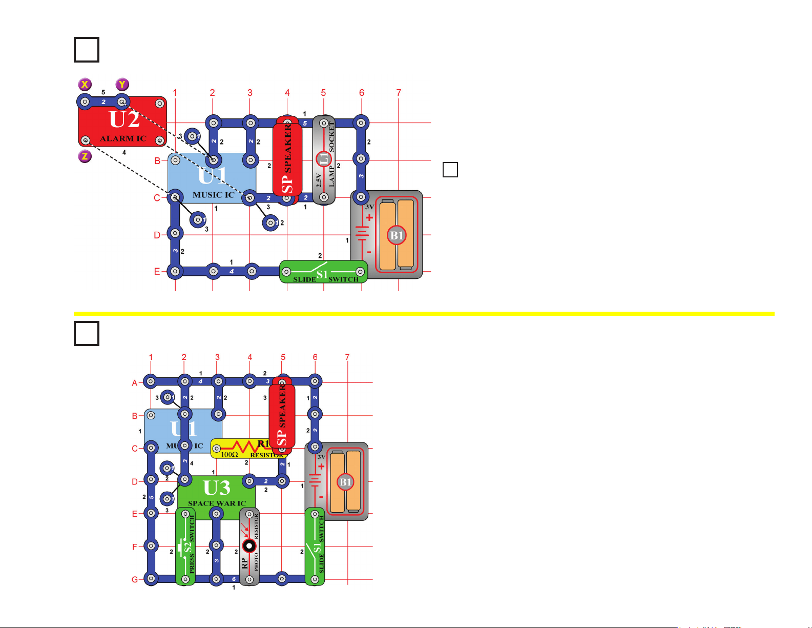
Project #82
Fan Symphony (II)
The preceding circuit may be too loud, so replace the speaker (SP) with
the whistle chip (WC).
The preceding circuit may be too loud, so replace the speaker (SP) with
the whistle chip (WC).
Project #80
Fire Fan Symphony (II)
Fan Symphony
OBJECTIVE: To combine sounds from the music, alarm, and
space war integrated circuits.
Modify the circuit from project #79 to match the circuit shown on the left.
The only differences are the connections around the alarm IC (U2). It
works the same way.
35
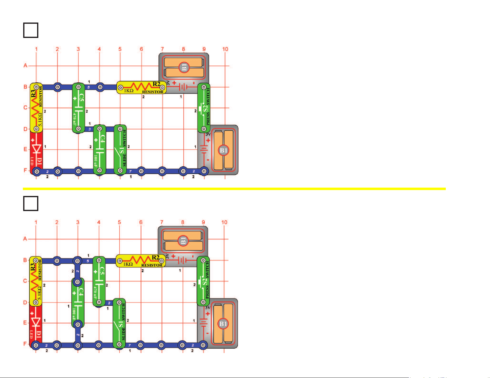
Project #83
Project #84
Capacitors in Series
OBJECTIVE: To compare types of circuits.
Capacitors in Parallel
OBJECTIVE: To compare types of circuits.
Turn on the slide switch (S1), then press and release the press switch
(S2). The LED (D1) becomes bright when the 470μF capacitor charges
up with the press switch on, then the LED slowly gets dim after you
release the press switch.
Now turn off the slide switch. Repeat the test with the slide switch off;
you’ll notice the LED goes out much faster after you release the press
switch. The much smaller 100μF capacitor (C4) is now in series with
the 470μF and so reduces the total capacitance (electrical storage
capacity), and they discharge much faster. (Note that this is opposite to
how resistors in series work).
Turn off the slide switch (S1), then press and release the press switch
(S2). The LED (D1) becomes bright when the 100μF capacitor charges
up with the press switch on, then the LED slowly gets dim after you
release the press switch.
Now turn on the slide switch and repeat the test; you’ll notice the LED
goes out much slower after you release the press switch. The much
larger 470μF capacitor (C5) is now in parallel with the 100μF and so
increases the total capacitance (electrical storage capacity), and they
discharge much slower. (Note that this is opposite to how resistors in
parallel work.)
36
Project #85
NPN Light Control
OBJECTIVE: To compare transistor circuits.
Project #86
NPN Dark Control
OBJECTIVE: To compare transistor circuits.
Turn on the slide switch (S1),
the brightness of the LED (D2)
depends on how much light
shines on the photoresistor
(RP). The resistance drops as
more light shines, allowing more
current to the NPN (Q2).
Turn on the slide switch (S1),
the brightness of the LED (D2)
depends on how LITTLE light
shines on the photoresistor (RP).
The resistance drops as more
light shines, diverting current
away from the NPN (Q2).
Project #87
Red & Green Control
OBJECTIVE: To show how the adjustable resistor works.
Project #88
Current Controllers
OBJECTIVE: To compare types of circuits.
Turn on the circuit using the
slide switch (S1) and/or the
press switch (S2) and move
the adjustable resistor’s (RV)
control lever around to adjust
the brightness of the LEDs (D1
& D2). When the adjustable
resistor is set to one side, that
side will have low resistance and
its LED will be bright (assuming
the switch on that side is ON)
while the other LED will be dim
or OFF.
Build the circuit and turn on
the slide switch (S1), the LED
(D1) will be lit. To increase the
LED brightness, turn on the press
switch (S2). To decrease the LED
brightness, turn off the slide switch.
With the slide switch on, the 5.1KW
resistor (R3) controls the current.
Turning on the press switch places
the 1KW resistor (R2) in parallel
with it to decrease the total circuit
resistance. Turning off the slide
switch places the 10KW resistor
(R4) in series with R2/R3 to
increase the total resistance.
37
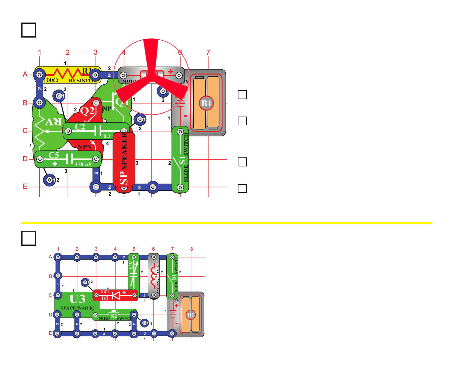
Project #89 Screaming Fan
OBJECTIVE: To have an adjustable resistance control a fan
and sounds.
Build the circuit on the left and place the fan onto the motor (M1). Turn
on the slide switch (S1) and move the setting on the adjustable resistor
(RV) across its range. You hear screaming sounds and the fan spins.
Project #91 Light Whining
Project #92 More Light Whining
Project #93 Motor That Won’t Start
Replace the 0.1μF capacitor (C2) with the 0.02μF capacitor (C1). The sounds
are now a high-pitch whine and the motor (M1) starts a little sooner.
Replace the 100W resistor (R1) at the upper-left of the circuit (points
A1 & A3 on the base grid) with the photoresistor (RP), and wave your
hand over it. The whining sound has changed a little and can now be
controlled by light.
Replace the 0.02mF capacitor (C1) with the 0.1mF capacitor (C2). The
sounds are lower in frequency and you can’t make the fan spin now.
Replace the 0.1μF capacitor (C2) with the 10μF capacitor (C3), put
the positive (+) side towards the left). It now makes clicking sounds
and the fan moves only in small bursts, like a motor that won’t start.
Project #90
Whining Fan
Project #94
Space War Radio
OBJECTIVE: To transmit Space War sounds to a AM radio.
Place the circuit next to an AM radio. Tune the radio so no stations are
heard and turn on the slide switch (S1). You should hear the space war
sounds on the radio. The red LED (D1) should also be lit. Adjust the
variable capacitor (CV) for the loudest signal. Push the press switch (S2)
to change the sound.
You have just performed the experiment that took Marconi (who invented
the radio) a lifetime to invent. The technology of radio transmission has
expanded to the point that we take it for granted. There was a time,
however, when news was only spread by word of mouth.
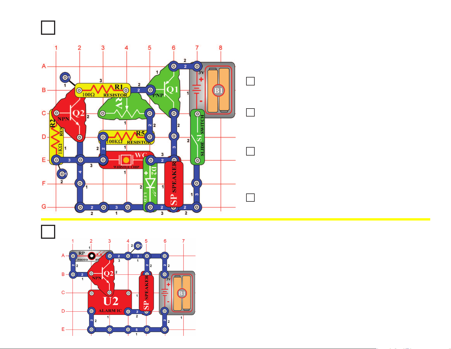
38
Project #95
Project #100
Whiner
OBJECTIVE: To build a circuit that makes a loud whine.
Light-controlled Alarm
OBJECTIVE: To show how light is used to turn an alarm.
Build the circuit, turn it on, and move the setting on the adjustable
resistor (RV). It makes a loud, annoying whine sound. The green LED
(D2) appears to be on, but it is actually ashing at a very fast rate.
The alarm will sound, as long as light is present. Slowly cover the
photoresistor (RP), and the volume goes down. If you turn off the lights,
the alarm will stop. The amount of light changes the resistance of the
photoresistor (less light means more resistance). The photoresistor and
transistor (Q2) act like a dimmer switch, adjusting the voltage applied to
the alarm.
This type of circuit is used in alarm systems to detect light. If an intruder
turned on a light or hit the sensor with a ashlight beam, the alarm
would trigger and probably force the intruder to leave.
Project #97 Hummer
Project #98 Adjustable Metronome
Project #99 Quiet Flasher
Place the 0.02μF capacitor (C1) above the whistle chip (WC) and vary the
adjustable resistor (RV) again. The frequency (or pitch) of the whine has been
reduced by the added capacitance.
Now place the 0.1μF capacitor (C2) above the whistle chip (WC) and
vary the adjustable resistor (RV) again. The frequency (or pitch) of
the whine has been reduced by the greater added capacitance and it
sounds more like a hum now.
Now place the 10μF capacitor (C3, “+” side on right) above the
whistle chip (WC) and vary the adjustable resistor (RV) again.
There is no hum now but instead there is a click and a ash of light
repeating about once a second, like the “beat” of a sound. It is like a
metronome, which is used to keep time for the rhythm of a song.
Leave the 10μF capacitor (C3) connected but replace the speaker
(SP) with the 2.5V lamp (L1).
Project #96
Lower Pitch Whiner
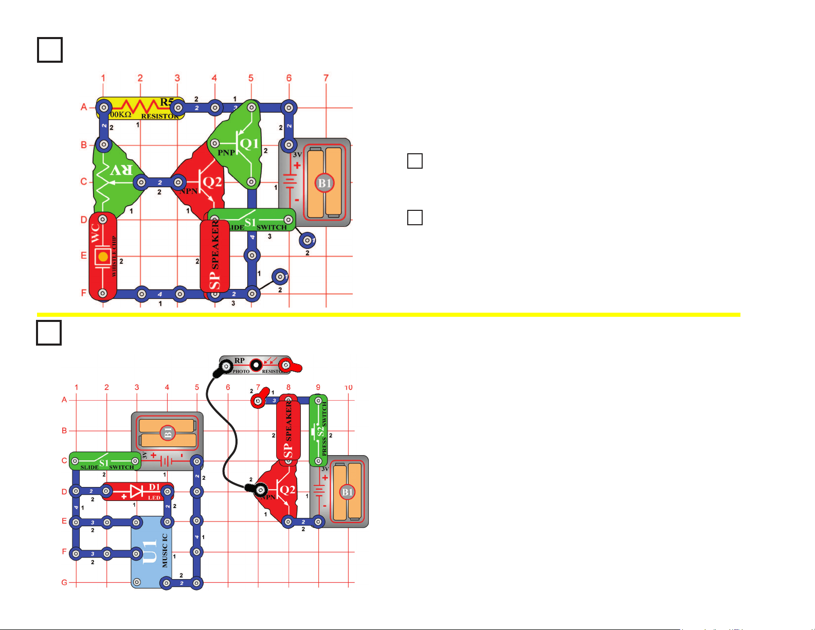
39
Project #101
Hissing Foghorn
OBJECTIVE: To build a transistor oscillator that can make a
foghorn sound.
Build the circuit on the left and move the adjustable resistor (RV)
setting. Sometimes it will make a foghorn sound, sometimes it will
make a hissing sound, and sometimes it will make no sound at all.
Project #103 Video Game Engine Sound
Modify the circuit in project #101 by replacing the 100kΩ resistor (R5) with the
photoresistor (RP). Move the adjustable resistor (RV) setting until you hear hissing
sounds, and then shield the photoresistor while doing so and you hear clicking sounds.
Remove the photoresistor (RP) from the circuit in project #102 and instead
touch your ngers between the contacts at points A4 and B2 on the base grid
while moving the adjustable resistor (RV). You hear a clicking that sounds
like the engine sound in auto-racing video games.
Project #102
Hissing & Clicking
Project #104
Build the circuit shown. Connect the photoresistor (RP) to the circuit
using the red & black jumper wires. Place the photoresistor upside
down over the red LED (D1), so the LED goes inside the photoresistor.
Turn on both switches (hold down the press switch button). Music
plays on the speaker, even though the two parts of the circuit are not
electrically connected.
The left circuit, with the LED and music IC (U1) creates a music signal
and transmits it as light. The right circuit, with the photoresistor and
speaker, receives the light signal and converts it back to music. Here
the photoresistor has to be on top of the LED for this to work, but better
communication systems (such as ber optic cables), can transmit
information over enormous distances at very high speeds.
Optical Transmitter &
Receiver
OBJECTIVE: To show how information can be transmitted
using light.
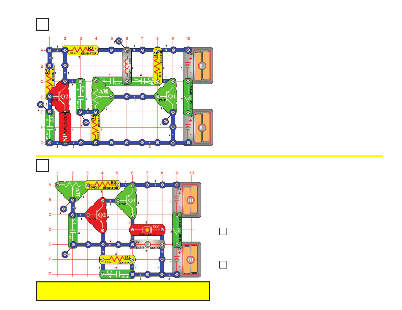
40
Pitch
OBJECTIVE: To show how to change the pitch of a sound.
Build the circuit on the left, turn it on, and vary the adjustable resistor
(RV). The frequency or pitch of the sound is changed. Pitch is the
musical profession’s word for frequency. If you’ve had music lessons, you
may remember the music scale using chords such as A3, F5, and D2 to
express the pitch of a sound. Electronics prefers the term frequency, as
in when you adjust the frequency on your radio.
Project #105
You need an AM radio for this project. Build the circuit shown but do
not turn on the slide switch (S1). Place it within a foot of your AM radio
and tune the radio frequency to the middle of the AM band (around 1000
kHz), where no other station is transmitting. Turn the volume up so
you can hear the static. Set the adjustable resistor (RV) control to the
middle setting. Turn on the slide switch and slowly tune the adjustable
capacitor (CV) until the static on the radio becomes quiet. You may
hear a whistle as you approach the proper tuning. In some cases you
may also need to set the adjustable resistor slightly off-center.
When the radio static is gone, tap on the speaker (SP) with your nger
and you should hear the sound of tapping on the radio. Now talk loudly
into the speaker (used here as a microphone) and you will hear your
voice on the radio. Set the adjustable resistor for best sound quality at
the radio.
Radio Announcer
OBJECTIVE: To hear your voice on the radio.
Project #106
Project #108 Pitch (III)
We’ve seen we can adjust the frequency by varying the resistance in the
adjustable resistor. You can also change frequency by changing the capacitance
of the circuit. Place the 0.1μF capacitor (C2) on top of the 0.02μF capacitor
(C1); notice how the sound has changed.
Remove the 0.1μF (C2) capacitor and replace the 100kΩ resistor (R5) with
the photoresistor (RP). Wave your hand up and down over the photoresistor to
change the sound. Changing the light on the photoresistor changes the circuit
resistance just like varying the adjustable resistance does.
Project #107
Pitch (II)
Note: If you have the adjustable resistor (RV) set to the right and light shining on the
photoresistor, then you may not get any sound because the total resistance is too
low for the circuit to operate.
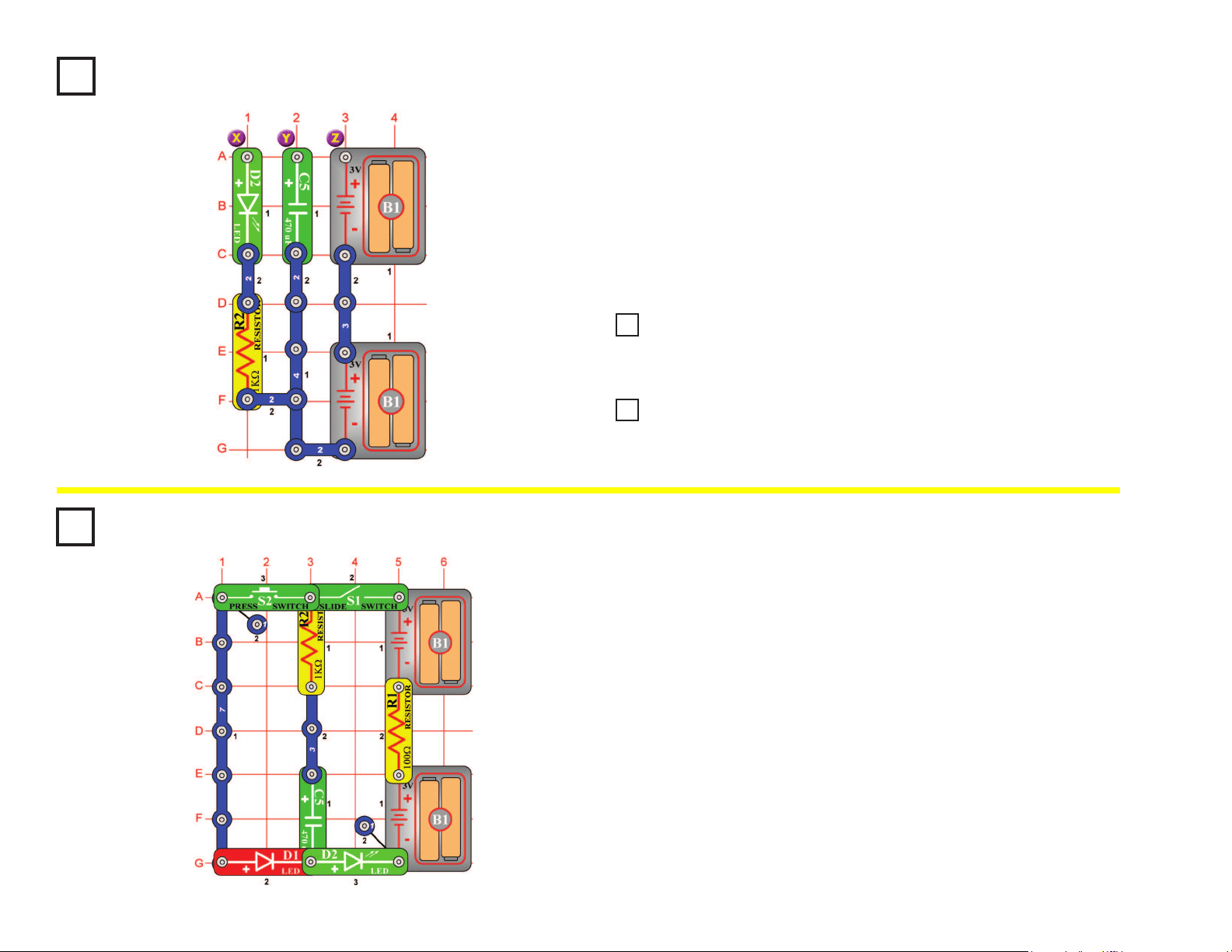
41
Project #109
Build the circuit, then connect points Y & Z (use a 2-snap wire) for a moment.
Nothing appears to happen, but you just lled up the 470mF capacitor (C5) with
electricity. Now disconnect Y & Z and instead touch a connection between X & Y.
The green LED (D2) will be lit and then go out after a few seconds as the electricity
you stored in it is discharged through the LED and resistor (R2).
Notice that a capacitor is not very efcient at storing electricity - compare how long
the 470mF kept the LED lit for with how your batteries run all of your projects! That is
because a capacitor stores electrical energy while a battery stores chemical energy.
Make Your Own Battery
OBJECTIVE: To demonstrate how batteries can store electricity.
Project #111 Make Your Own Battery (III)
In the preceding circuit, replace the 470μF capacitor (C5) with the 100μF
capacitor (C3) and repeat the test. You see that the LED (D2) goes out faster,
because the 100μF capacitor does not store as much electricity as the 470μF.
Now replace the 1kW resistor (R2) with the 100W resistor (R1)
and try it. The LED (D2) gets brighter but goes out faster because
less resistance allows the stored electricity to dissipate faster.
Project #110
Make Your Own Battery (II)
Project #112
Turn on the slide switch (S1) for a few seconds, then turn it off. The
green LED (D2) is initially bright but goes dim as the batteries (B1)
charge up the 470mF capacitor (C5). The capacitor is storing electrical
charge.
Now press the press switch (S2) for a few seconds. The red LED (D1) is
initially bright but goes dim as the capacitor discharges itself through it.
The capacitor value (470mF) sets how much charge can be stored in it,
and the resistor value (1kW) sets how quickly that charge can be stored
or released.
Capacitor Charge &
Discharge
OBJECTIVE: To show how capacitors store and release
electrical charge.
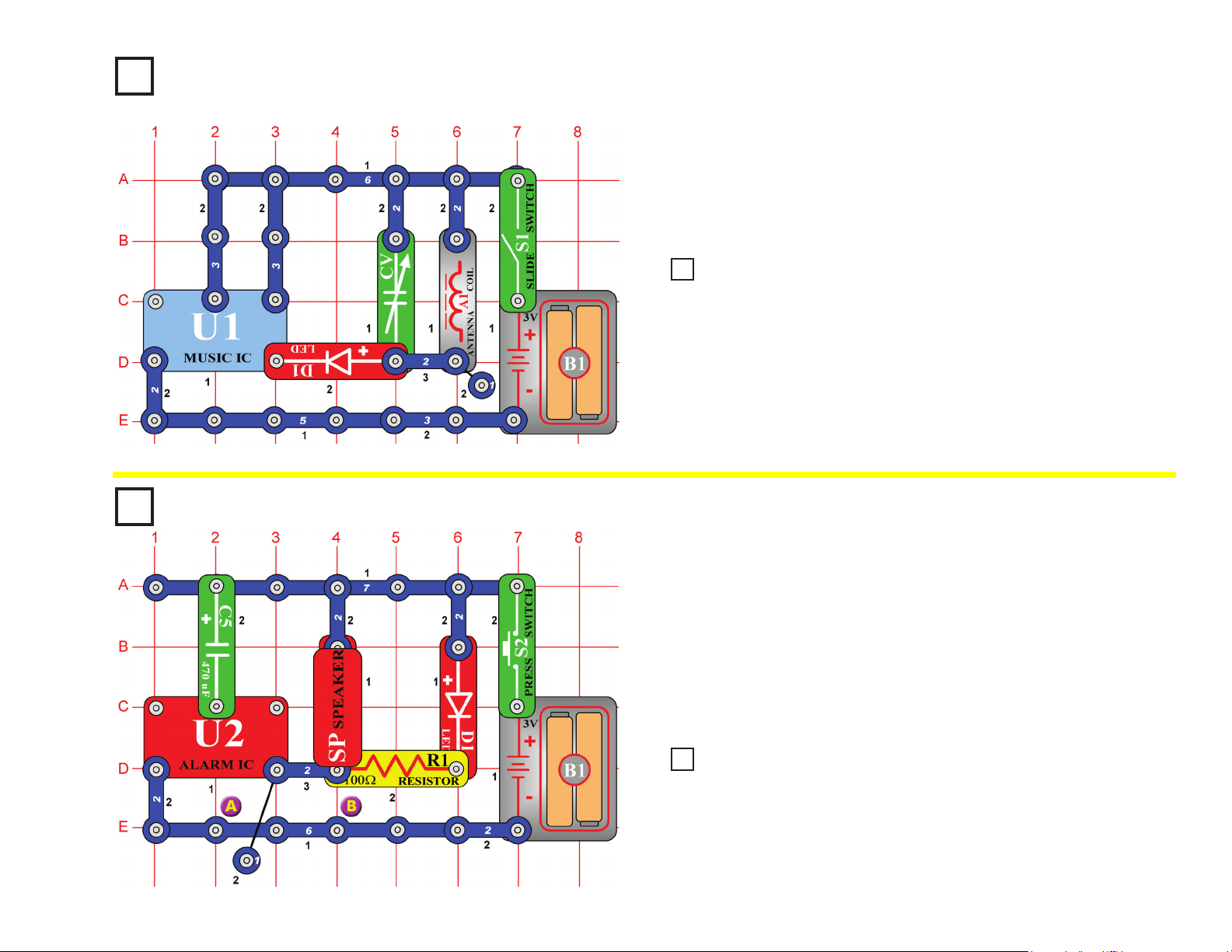
42
Music Radio Station
OBJECTIVE: To create music and transmit it to a radio.
You need an AM radio for this project. Build the circuit shown on the
left and turn on the slide switch (S1). Place it next to your AM radio and
tune the radio frequency to where no other station is transmitting.
Then, tune the variable capacitor (CV) until your music sounds best on
the radio.
Project #115
Fading Siren
OBJECTIVE: To produce sound of a siren driving away into
the distance.
Press the press switch (S2), the alarm IC (U2) should make the sound of
an up-down siren that gets weaker with time. The fading is produced by
the charging of the 470mF capacitor (C5). After it is charged the current
stops and the sound is very weak.
To repeat this effect you must release the press switch, remove the
capacitor, and discharge it by placing it across the snaps on the bottom
bar marked A & B. Then, replace the capacitor and press the switch again.
Project #113
Replace the music IC (U1) with the alarm IC (U2), and then you will hear
a machine gun sound on the radio. You may need to re-tune the variable
capacitor (CV).
Replace the 470μF capacitor (C5) with the 100μF capacitor (C4), the siren
fades faster.
Project #114
Alarm Radio Station
Project #116
Fast Fade Siren

43
Project #117
Laser Gun with Limited
Shots
OBJECTIVE: To build a circuit with laser gun sounds and a
limited amount of shots.
Symphony of Sounds
OBJECTIVE: To combine sounds from the music, alarm, and
space war integrated circuits.
Build the circuit shown. Turn it on and press the press switch (S2)
several times and wave your hand over the photoresistor (RP) to hear
the full symphony of sounds that this circuit can create. Have fun!
When you press the press switch (S2), the alarm IC (U2) should start
sounding a very loud laser gun sound. The speaker (SP) will sound,
simulating a burst of laser energy. You can shoot long repeating laser
burst, or short zaps by tapping the trigger switch. But be careful, this
gun will run out of energy and you will have to wait for the energy pack
(C5) to recharge. This type of gun is more like a real life laser gun
because power would run out after a few shots due to energy drain. In
a real laser, the energy pack would have to be replaced. Here you only
have to wait a few seconds for recharge.
Project #118
Project #119 Symphony of Sounds (II)
The preceding circuit may be too loud, so replace the speaker
(SP) with the whistle chip (WC).
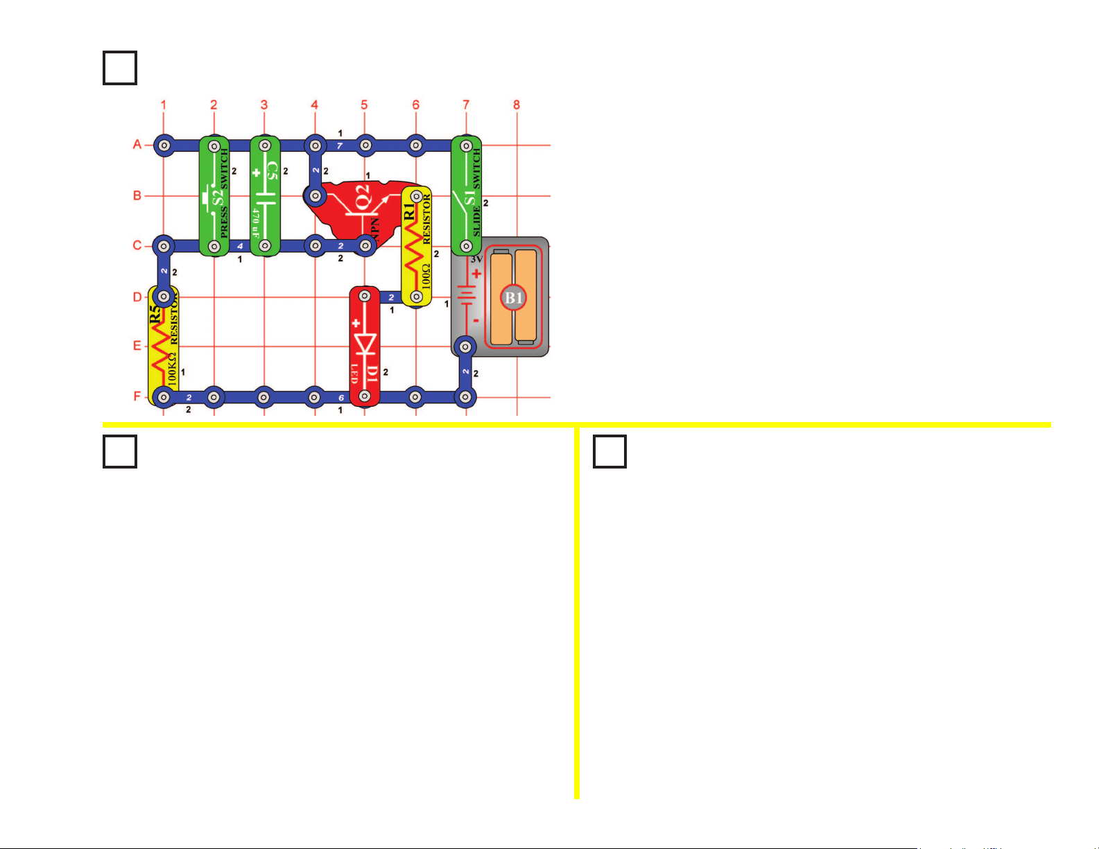
44
Project #120
Auto-Off Night-Light
OBJECTIVE: To learn about one device that is used to delay
actions in electronics.
Use the circuit from project #120 shown above.
When you rst turned on the slide switch (S1) in project
#120, the LED (D1) came on and very slowly got dimmer and
dimmer. When you turned the slide switch (S1) off and back
on after the light went out, it did NOT come on again. The
470mF capacitor (C5) was charged and everything stopped.
This time turn the slide switch off. Then press the press
switch (S2) for a moment to discharge the 470mF capacitor.
Now when you turn the slide switch back on the delay
repeats. Shorting a capacitor with a low resistance will allow
the charges on the capacitor to leave through the resistance.
In this case, the low resistance was the press switch.
Project #121
Discharging Caps
OBJECTIVE: To show how capacitor delays can be
repeated by discharging the capacitor.
Project #122
Changing Delay Time
OBJECTIVE: To show how the size of the capacitor
effects the delay time.
When you turn on the slide switch (S1) the rst time the LED (D1) will
come on and very slowly get dimmer and dimmer. If you turn the slide
switch (S1) off and back on after the light goes out it will NOT come
on again. The 470mF capacitor (C5) has charged up and the NPN
transistor amplier (Q2) can get no current at its input to turn it on.
This circuit would make a good night-light. It would allow you to get
into bed, and then it would go out. No further current is taken from the
battery so it will not drain the batteries (B1) even if left on all night.
Use the circuit from project #120 shown above.
Change the 470mF capacitor (C5) to the 100mF capacitor (C4).
Make sure the capacitor (C4) is fully discharged by pressing
the press switch (S2) before closing the on-off slide switch
(S1). When slide switch is turned on, notice how much quicker
the LED (D1) goes out. Since 100mF is approximately 5 times
smaller than 470mF, the LED will go out 5 times faster. The
bigger the capacitor the longer the delay.
In electronics, capacitors are used in every piece of equipment to
delay signal or tune circuits to a desired frequency.
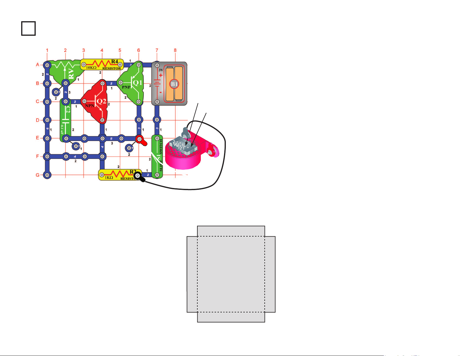
45
Project #123 Sound Wave Magic
OBJECTIVE: To show how sound waves travel on a paper
surface.
Build the circuit shown on the left and connect the speaker (SP) using
the two (2) jumper wires. Then, lay the speaker on a at hard surface.
Setup: Use some paper and scissors to cut out a rectangular pattern.
Use the one shown below as a guide. Use colored paper if available.
Fold at the points shown. Scotch tape the corners so the tray has no
cracks at the corners. Place the tray over the speaker and sprinkle a
small amount of white table salt in the tray. There should be enough
salt to cover the bottom with a little space between each salt grain.
Sound Magic: Turn on the circuit by turning on the slide switch (S1).
Adjust the adjustable resistor (RV) for different pitches and watch the
salt particles. Particles that bounce high are directly over the vibrating
paper and ones that do not move are in the nodes where the paper is
not vibrating. Eventually, all the salt will move to the areas that have
no vibration, and stay there. Change the position of the tray and the
material used to create different patterns due to the sound. Try sugar
and coffee creamer, for example, to see if they move differently due to
the sound waves.
Paper Tray
Salt
Sample Cut-out Pattern
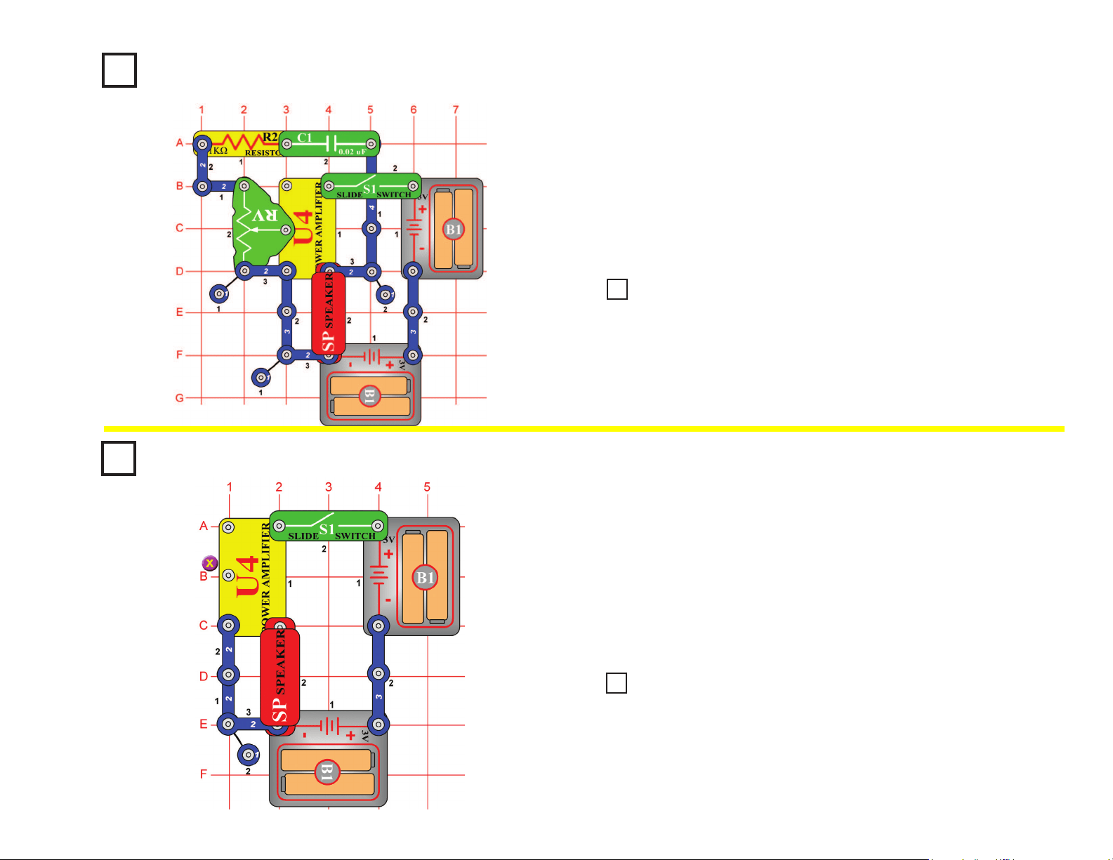
46
Project #124
Project #126
When you turn on the slide switch (S1) the trombone should start playing.
To change the pitch of the note, simply slide the adjustable resistor (RV)
control back and forth. By turning the slide switch on and off and moving
the slider, you will be able to play a song much like a trombone player
makes music. The switch represents air going through the trombone, and
the adjustable resistor control is the same as a trombone slider bar. The
circuit may be silent at some positions of the resistor control.
When you turn on the slide switch (S1), the power amplier IC (U4)
should not oscillate. You should be able to touch point X with your
nger and hear static. If you do not hear anything, listen closely and wet
your nger that touches point X. High frequency clicks or static should
be coming from speaker (SP) indicating that the amplier is powered on
and ready to amplify signals.
The power amplier may oscillate on its own. Do not worry, this is
normal with high gain high-powered ampliers.
Trombone
OBJECTIVE: To build an electronic trombone that changes
pitch of note with slider bar.
Power Amplier
OBJECTIVE: To check stability of power amplier with open input.
Use the circuit from project #124 shown on the left, but change the 0.02μF
capacitor (C1) to a 10μF capacitor (C3). Make sure the positive (+) mark
on the capacitor is NOT on the resistor (R2) side when you snap it in.
When the slide switch (S1) is turned on, you should hear a very low
frequency oscillation. By sliding the adjustable resistor (RV) control up and
down, you should be able to make the sound of a race car engine as it’s
motor speeds up and slows down.
Use the circuit from project #126. When you place one nger on point X
and a nger from your other hand on the speaker (SP) snap that is not
connected to the battery (B1), what happens? If the amplier starts to
oscillate it is due to the fact that you just provided a feedback path to make
the amplier into an oscillator. You may even be able to change the pitch of
the oscillation by pressing harder on the snaps. This is the principle used to
make an electronic kazoo. If you practice and learn the amount of pressure
required to make each note, you may even be able to play a few songs.
Project #125
Race Car Engine
Project #127
Feedback Kazoo
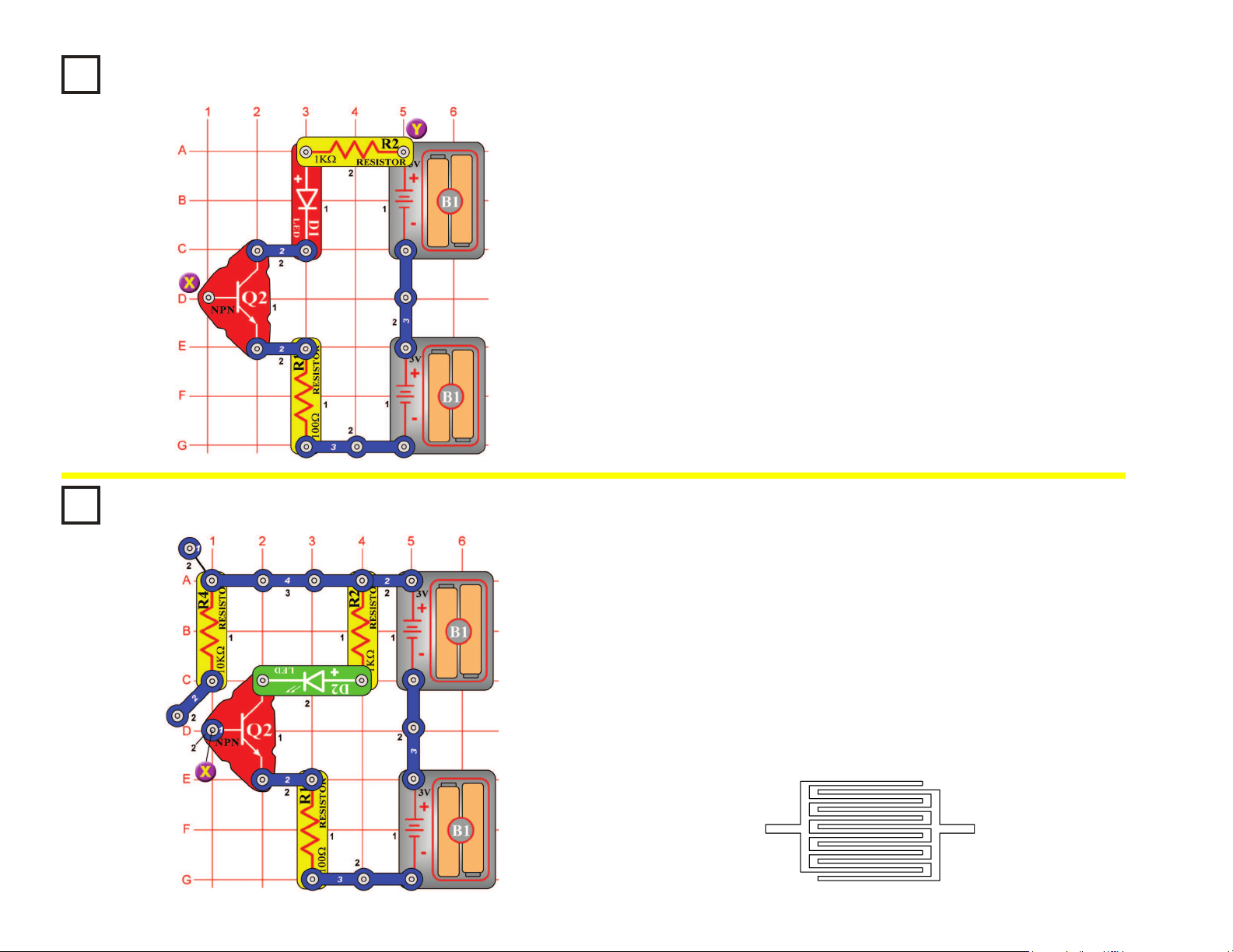
47
Project #128
Build the circuit on the left. You’re probably wondering how it can work,
since one of the points on the NPN transistor (Q2) is unconnected. It can’t,
but there is another component that isn’t shown. That component is you.
Touch points X & Y with your ngers. The LED (D1) may be dimly lit. The
problem is your ngers aren’t making a good enough electrical contact
with the metal. Wet your ngers with water or saliva and touch the points
again. The LED should be very bright now. Think of this circuit as a touch
lamp since when you touch it, the LED lights. You may have seen such a
lamp in the store or already have one in your home.
Two-Finger Touch Lamp
OBJECTIVE: To show that your body can be used as an
electronic component.
Project #129
The touch lamps you see in stores only need to be touched by one
nger to light, not two. So let’s see if we can improve the last circuit to
only need one nger. Build the new circuit, note that near point X there
is a 2-snap wire that is only mounted on one side, swing it so the plastic
touches point X. Wet a large area of one of your ngers and touch it to
both metal contacts at point X at the same time; the LED (D2) lights. To
make it easier for one nger to touch the two contacts, touch lamps or
other touch devices will have the metal contacts interweaved as shown
below and will also be more sensitive so that you don’t have to wet your
nger to make good contact.
One-Finger Touch Lamp
OBJECTIVE: To show you how nger touch lamps work.
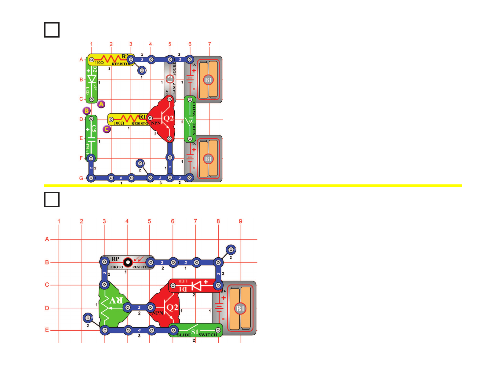
48
Project #130
Storing Electricity
OBJECTIVE: To store electricity in a capacitor.
Turn the slide switch (S1) on and connect points A & B with a 2-snap
wire. The green LED (D2) will ash and the 470mF capacitor (C5) will be
charged with electricity. The electricity is now stored in the capacitor.
Disconnect points A & B. Connect points B & C and there will be a ash
from the 6V lamp (L2).
The capacitor discharges through the resistor to the base of the NPN
transistor (Q2). The positive current turns on the transistor like a switch,
connecting the lamp to the negative (–) side of the batteries. The light
will go out after the capacitor discharges, because there is no more
current at the base of the transistor.
Project #131
Set the adjustable resistor (RV) to the center position. Turn the slide switch
(S1) on and the LED (D1) lights. Wave your hand over the photoresistor
(RP) and the LED turns off and on. The resistance changes as the amount
of light strikes the photoresistor. As the light decreases, the resistance
increases. The increased resistance lowers the voltage at the base of the
NPN transistor (Q2). This turns off the transistor, preventing current owing
through the LED to the negative (–) side of the battery (B1). Wave your
hand over photoresistor at different distances. The LED gets brighter the
farther away your hand is.
Motion Detector
OBJECTIVE: Build a circuit that detects motion.
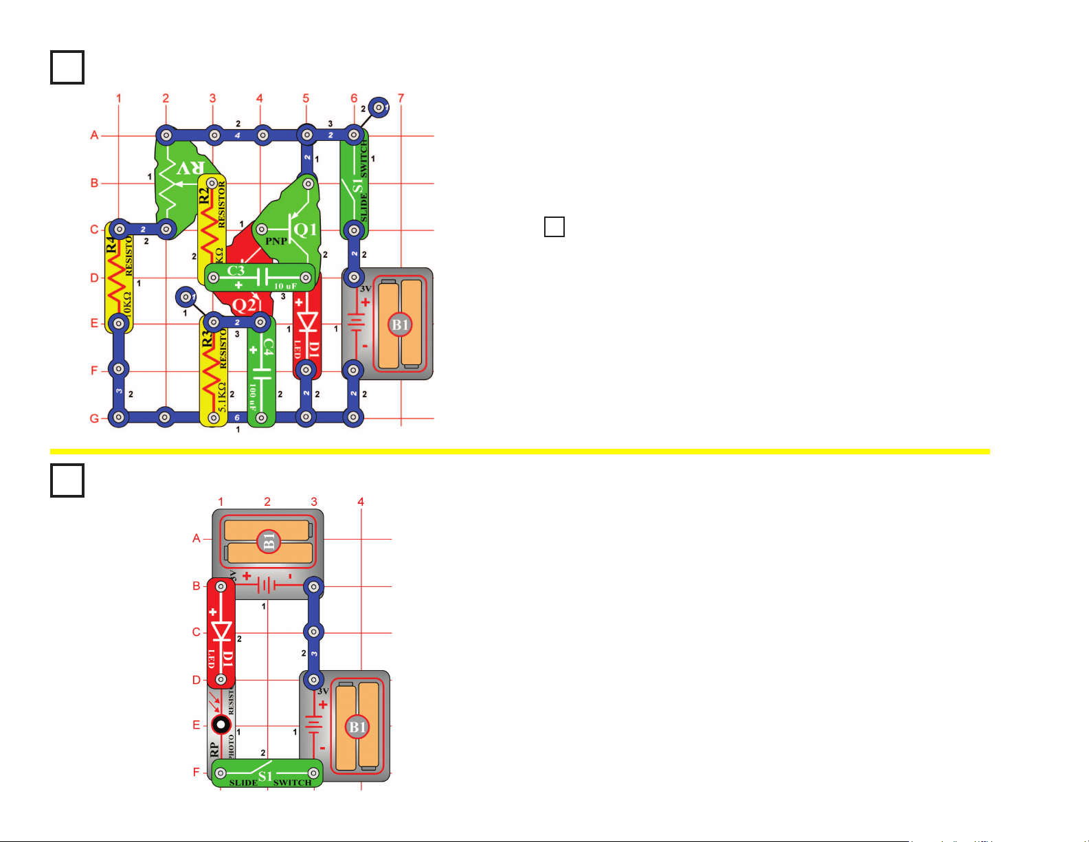
49
Photoresistor Control
OBJECTIVE: To use a photoresistor to control the brightness of an LED.
In this circuit, the brightness of the LED (D1) depends on how much light
shines directly on the photoresistor (RP). If the photoresistor were held
next to a ashlight or other bright light, then the LED would be very bright.
The resistance of the photoresistor decreases as more light shines on it.
Photoresistors are used in applications such as streetlamps, which come
on as it gets dark due to night or a severe storm.
Project #132
Project #134
Set the adjustable resistor (RV) to the bottom position and then turn the
slide switch (S1) on. The LED (D1) will start ashing at a frequency of
0.5Hz (once every two seconds). Slowly adjust the adjustable resistor and
the LED ashes faster. As the frequency increases, the LED ashes faster.
Eventually, the LED ashes so fast, it looks like it is on all of the time.
Oscillator 0.5 - 30Hz
OBJECTIVE: To build a 0.5Hz - 30Hz oscillator that will light an LED.
Use the circuit from project #132.
Connect a single snap under the speaker (SP) and then connect it across
the LED (on level 4). Turn the slide switch (S1) on and now you can hear
the oscillator. Adjust the adjustable resistor (RV) to hear the different
frequencies. Now you can hear and see the frequencies. Note: You may
not hear sounds at all settings of the adjustable resistor.
Project #133
Sound Pulse Oscillator
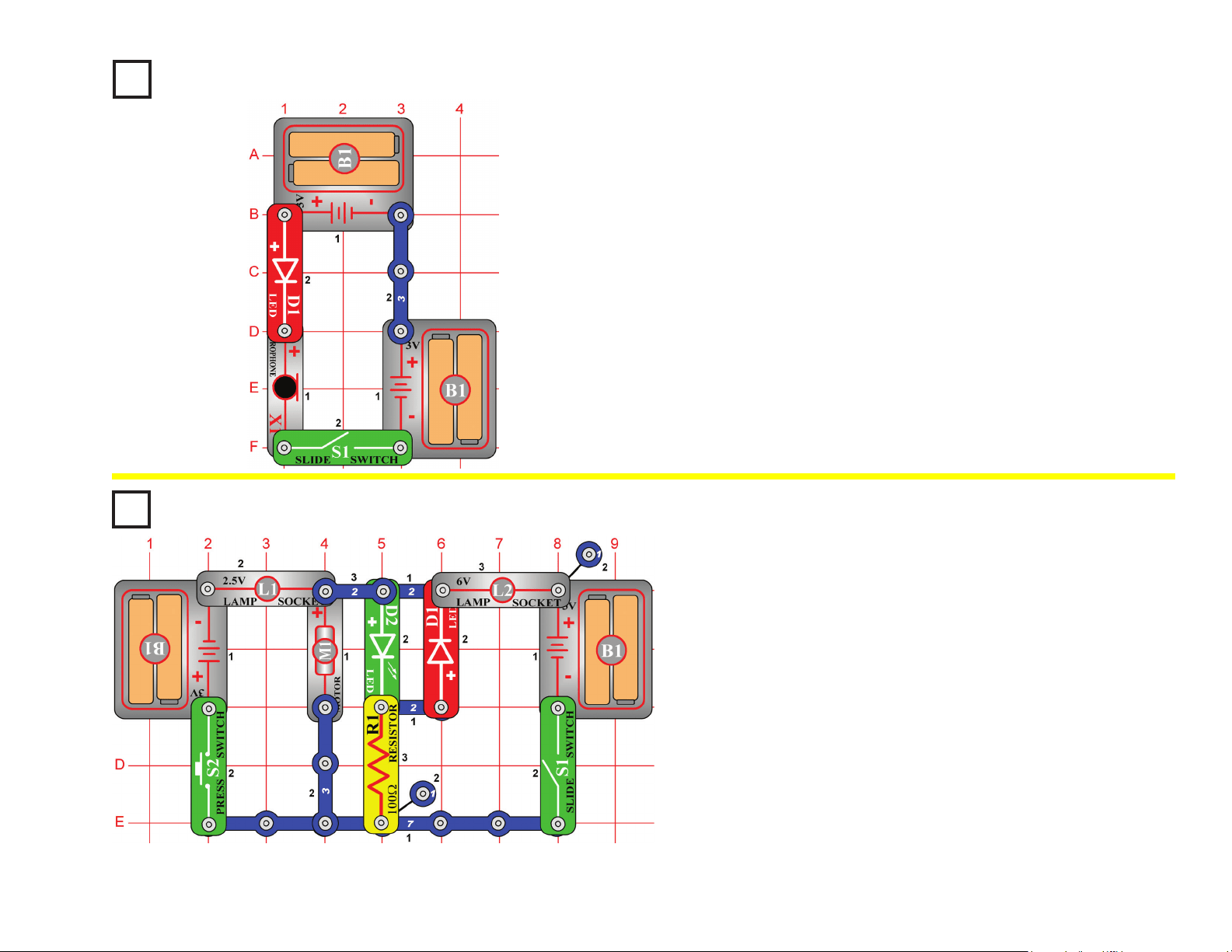
50
Microphone Control
OBJECTIVE: To use a microphone to control the brightness of
an LED.
In this circuit, blowing on the microphone (X1) changes the LED (D1)
brightness.
The resistance of the microphone changes when you blow on it. You
can replace the microphone with one of the resistors to see what
resistor value it is closest to.
Project #136
Do not place the fan onto the motor (M1). Turn the slide switch (S1) on. The
motor rotates clockwise, and the green LED (D2) lights. When you connect
the positive (+) side of the battery (B1) to the positive (+) side of the motor,
it spins clockwise. Turn the slide switch off and press the press switch (S2).
Now the fan spins the other way and the red LED (D1) lights. The positive
(+) side of the battery is connected to the negative (–) side of the motor.
The polarity on the motor determines which way it rotates.
Now place the fan on the motor, and turn on S1 or S2 (not both). Now one
of the lamps (L1 or L2) lights as the motor spins, but the LED is dim.
The motor needs a lot of current to spin the fan, but only a little current to
spin without it. In this circuit, a lamp lights when the motor current is high,
and an LED lights when the motor current is low. The lamps also prevent a
short circuit if both switches are on.
LED Fan Rotation
Indicator
OBJECTIVE: To build an LED fan rotation indicator.
Project #135
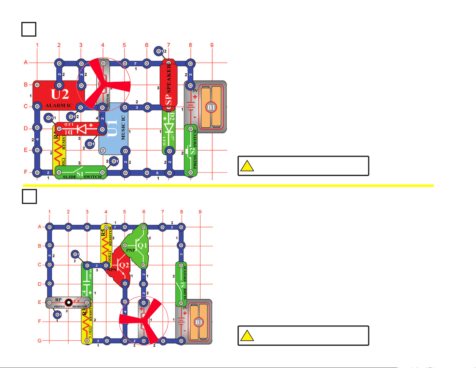
51
Project #137
Build the circuit shown on the left. Place the fan onto the motor (M1).
In the circuit, the alarm IC (U2) and the music IC (U1) are connected
together. The sounds from both ICs can be played at the same time.
Press the press switch (S2). The music IC plays and the green LED
(D2) lights. Now turn on the slide switch (S1) and press the press switch
again. You should hear the sounds from both ICs playing. As the alarm
IC plays, it also drives the fan and the red LED (D1).
Sound Mixer Fan Driver
OBJECTIVE: To connect two sound ICs together to drive two
LEDs and a motor.
Project #138
Place the fan on the motor (M1). Turn on the slide switch (S1), the
motor starts spinning. As you move your hand over the photoresistor,
(RP) the motor slows. Now place a nger on top of the photoresistor
to block the light. The motor slows down. In a few seconds the motor
speeds up again.
The fan will not move on most settings of the resistor, because the
resistance is too high to overcome friction in the motor. If the fan does
not move at any resistor setting, then replace your batteries.
Start-Stop Delay
OBJECTIVE: To start and stop a motor with light.
!
WARNING: Moving parts. Do not touch the fan or
motor during operation. Do not lean over the motor.
!
WARNING: Moving parts. Do not touch the fan or
motor during operation. Do not lean over the motor.
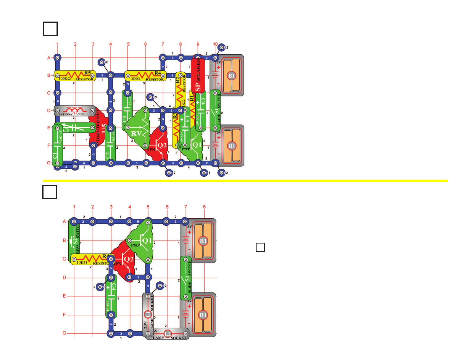
52
Project #139
AM Radio with
Transistors
OBJECTIVE: To build a complete, working AM radio with
transistor output.
When you turn on the slide switch (S1), the integrated circuit (U5)
should amplify and detect the AM radio waves. Tune the variable
capacitor (CV) to the desirable station. Set the adjustable resistor (RV)
for the best sound. The two transistors (Q1 & Q2) drive the speaker
(SP) to complete the radio. The radio will not be very loud.
Note: 5-snap wire is connected
from base grid locations G3 to G7.
Delayed Action Lamp
OBJECTIVE: To build a lamp that stays on for a while.
Turn on the slide switch (S1) and press the press switch (S2). The
lamps (L1 & L2) turn on slowly, but stay on for a while after you release
the press switch.
Project #140
Replace the lamp (L1) with the motor (M1), positive (+) side up. Be sure
to put on the fan. Turn on the slide switch (S1) and press the press switch
(S2). The fan turns on slowly but stays on for a while after you release the
press switch.
Project 141
Delayed Action Fan
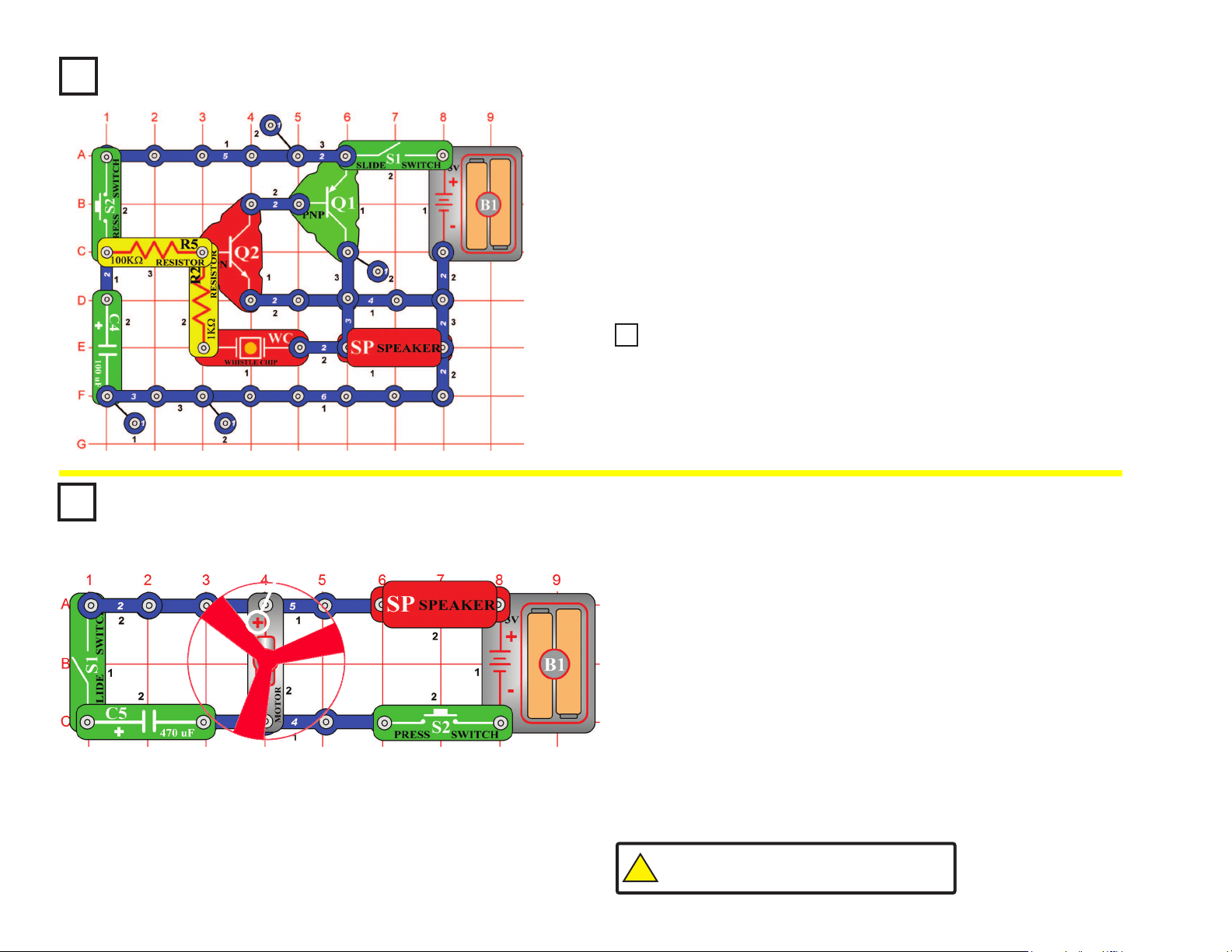
53
Lasting Doorbell
OBJECTIVE: To build a doorbell that stays on for a while.
Build the circuit at left, note that there is a 4-snap wire on layer 1 that is
not connected to a 3-snap wire that runs over it on layer 3. Turn on the
slide switch (S1), then press and release the press switch (S2). There is
a doorbell sound that slowly fades away.
When the press switch is pressed, the transistors are supplied with
current for oscillation. At the same time, the 100mF capacitor (C4)
is being charged. When the press switch is released, the capacitor
discharges and keeps the oscillation going for a while.
Project #144
Place the fan on the motor (M1) and turn off the slide switch (S1).
Press the press switch (S2) and listen to the motor.
As the motor shaft spins around it connects/ disconnects several sets
of electrical contacts. As these contacts are switched, an electrical
disturbance is created, which the speaker converts into sound.
Turn on the slide switch and push the press switch again. The fan
spins just as fast, but the sound is not as loud. Capacitors, like the
470mF capacitor (C5), are often used to lter out undesired electrical
disturbances. If you replace C5 with one of the other capacitors in your
set then the sound will not be changed as much.
Quieting a Motor
OBJECTIVE: To show how capacitors can lter out electrical
disturbances.
Project #142
!
WARNING: Moving parts. Do not touch the fan or
motor during operation. Do not lean over the motor.
Place the 10μF capacitor (C3) on top of the whistle chip (WC). Press and
release the press switch (S2). It makes a clicking sound that repeats for a while.
Project #143
Lasting Clicking
+
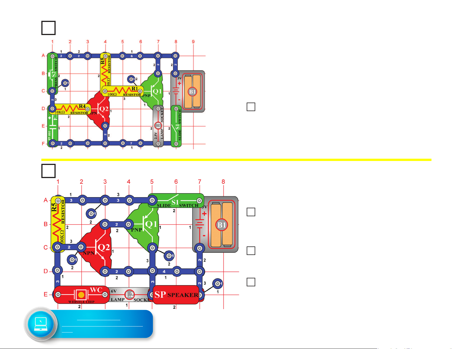
54
Project #147
Build the circuit and turn it on, you hear a high-frequency sound.
Tone Generator
OBJECTIVE: To build a high-frequency oscillator.
Watch Light
OBJECTIVE: To build a lamp that stays on for a while.
Turn on the switch and press the press switch (S2). The lamp stays on
for a few seconds after you release the press switch.
A miniature version of a circuit like this might be in your wristwatch -
when you press a light button on the watch to read the time in the dark,
a light comes on but automatically turns off after a few seconds to avoid
draining the battery.
Project #145
Replace the lamp (L1) with the motor (M1, positive (+) side up), be sure
to put on the fan. Turn on the switch and press the press switch (S2). The
fan stays on for a while after you release the press switch. This could have
a longer delay and be near your bed, to turn off after you fall asleep.
Place the 0.02μF capacitor (C1) on top of the whistle chip (WC) in the
preceding circuit, you hear a middle-frequency sound. Why? The whistle chip
is used here as a capacitor and by placing the 0.02μF on top (in parallel) we
have increased the capacitance, and doing so lowers the frequency.
Next, replace the 0.02μF capacitor (C1) and the whistle chip (WC) with the
larger 0.1μF capacitor (C2). You now hear a low frequency sound, due to yet
more capacitance.
Now replace the 0.1μF (C2) with the much larger 10μF capacitor (C3), (orient
with the positive (+) side towards the left); the circuit just clicks about once a
second. There isn’t a constant tone anymore due to other transistor properties.
You need a different type of circuit to create very low frequency tones.
Project #146 Delayed Bedside Fan
Project #148 Tone Generator (II)
Project #149 Tone Generator (III)
Project #150 Tone Generator (IV)
Go to shop.elenco.com/
consumers/snap-circuits-classic.
html to download projects 151-305
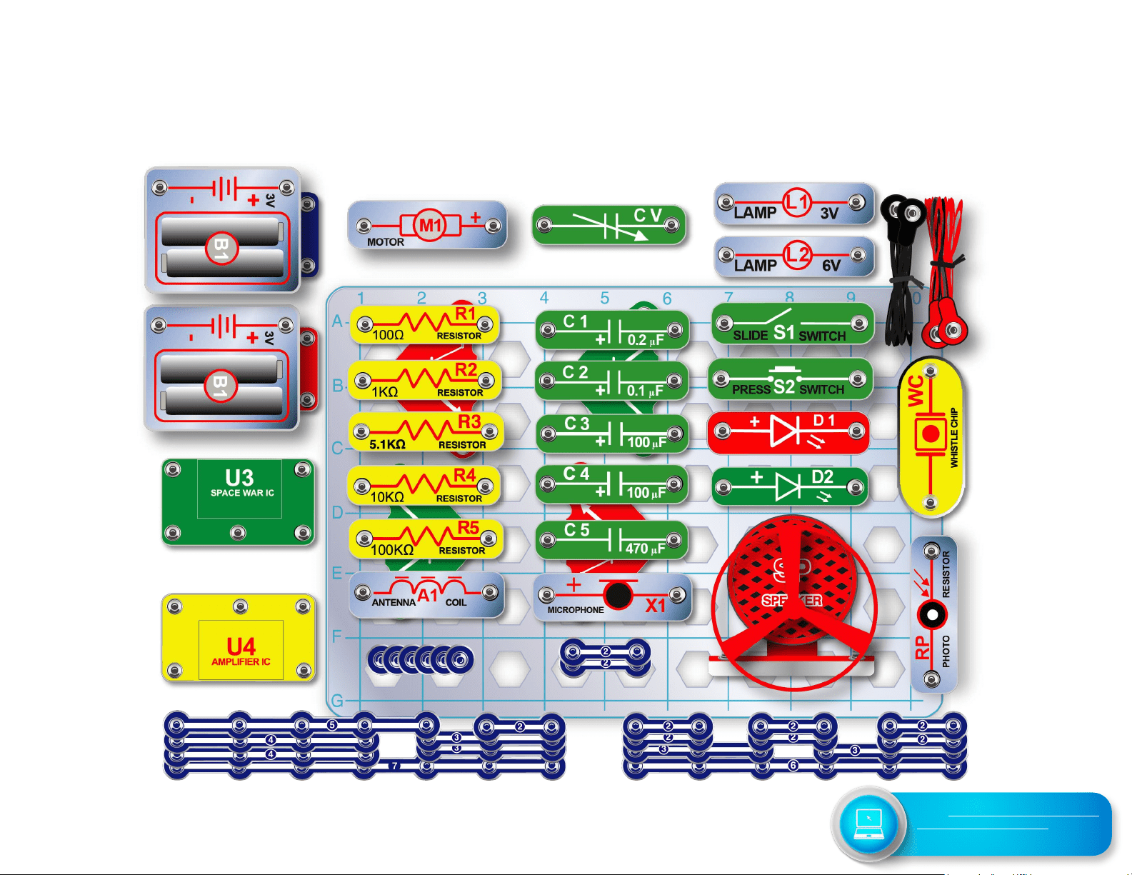
55
SC-300 Snap Circuits
®
Block Layout
Important: If any parts are missing or damaged, DO NOT RETURN TO RETAILER. Call toll-free (800) 533-2441 or
e-mail us at: [email protected]. Customer Service • 150 Carpenter Ave. • Wheeling, IL 60090 U.S.A.
Go to shop.elenco.com/consumers/
snap-circuits-classic.html to
download projects 151-305