Go to https://shop.elenco.com/
consumers/snap-circuits-arcade.
html to download projects 62-203
Copyright
©
2021 by Elenco
®
Electronics, Inc. All rights reserved. No part of this book shall be reproduced by any means;
electronic, photocopying, or otherwise without written permission from the publisher. SOURCE CODE:SCA-200V1 | REV-B | 753077

1
1.
Most circuit problems are due to incorrect assembly, always
double-check that your circuit exactly matches the drawing for it.
2. Be sure that parts with positive/negative markings are
positioned as per the drawing.
3. Be sure that all connections are securely snapped.
4. Try replacing the batteries.
5. If the programmable fan (M8) does not display any
messages, then it could be because you erased them without
programming in new ones. See project 15 for instructions on
how to program it.
Elenco
®
is not responsible for parts damaged due to
incorrect wiring.
Basic Troubleshooting
Note: If you suspect you have damaged parts, you can follow the
Advanced Troubleshooting procedure on page 10 to determine which
ones need replacing.
Basic Troubleshooting 1
Parts List 2
How to Use Snap Circuits
®
3
About Your Snap Circuits
®
Parts 4-6
Summary of Games in the LED MC (U29) 7
Introduction to Electricity 8
DOs and DON’Ts of Building Circuits 9
Advanced Troubleshooting 10
Projects 1 - 61 11-30
WARNING: SHOCK HAZARD - Never connect
Snap Circuits
®
to the electrical outlets in your home
in any way!
Table of Contents
WARNING: Always check your
wiring before turning on a circuit.
Never leave a circuit unattended
while the batteries are installed.
Never connect additional batteries
or any other power sources to your
circuits. Discard any cracked or
broken parts.
Adult Supervision:
Because children’s abilities vary
so much, even with age groups,
adults should exercise discretion
as to which experiments are
suitable and safe (the instructions
should enable supervising adults
to establish the experiment’s
suitability for the child). Make sure
your child reads and follows all of
the relevant instructions and safety
procedures, and keeps them at
hand for reference.
This product is intended for use
by adults and children who have
attained sufcient maturity to read
and follow directions and warnings.
Never modify your parts, as doing
so may disable important safety
features in them, and could put
your child at risk of injury.
● Use only 1.5V AA type, alkaline
batteries (not included).
● Insert batteries with correct
polarity.
● Non-rechargeable batteries
should not be recharged.
Rechargeable batteries should
only be charged under adult
supervision, and should not be
recharged while in the product.
● Do not connect batteries or
battery holders in parallel.
● Do not mix old and new batteries.
● Do not mix alkaline, standard
(carbon-zinc), or rechargeable
(nickel-cadmium) batteries.
● Remove batteries when they are
used up.
● Do not short circuit the battery
terminals.
● Never throw batteries in a re or
attempt to open its outer casing.
●
Batteries are harmful if swallowed,
so keep away from small children.
Batteries:
!
WARNING: CHOKING HAZARD - Small parts. Not
for children under 3 years.
!
Conforms to all applicable
government requirements
WARNING: Moving parts. Do not
touch the fan while it is spinning.
!
Go to https://shop.elenco.com/
consumers/snap-circuits-arcade.
html to download projects 62-203
2
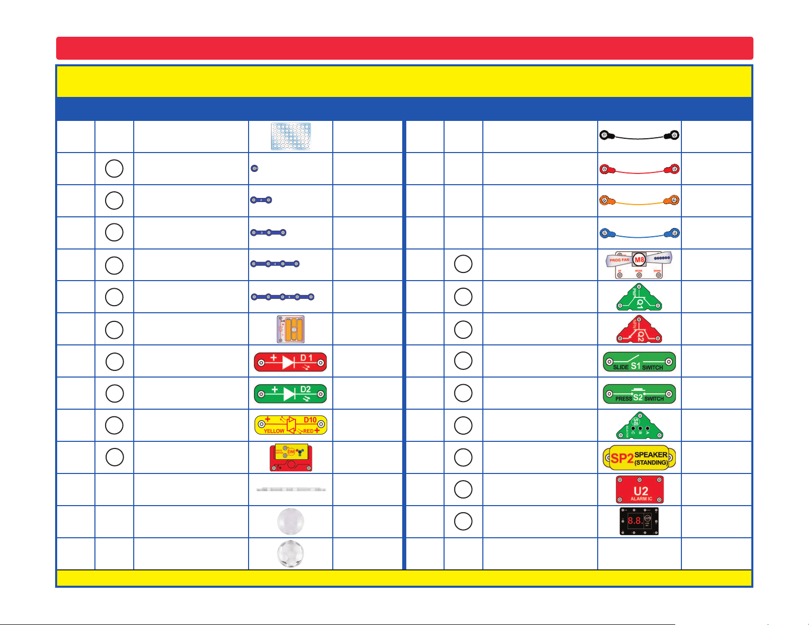
Important: If any parts are missing or damaged, DO NOT RETURN TO RETAILER. Call toll-free (800) 533-2441 or e-mail us at: help@
elenco.com. Customer Service ● 150 Carpenter Ave. ● Wheeling, IL 60090 U.S.A.
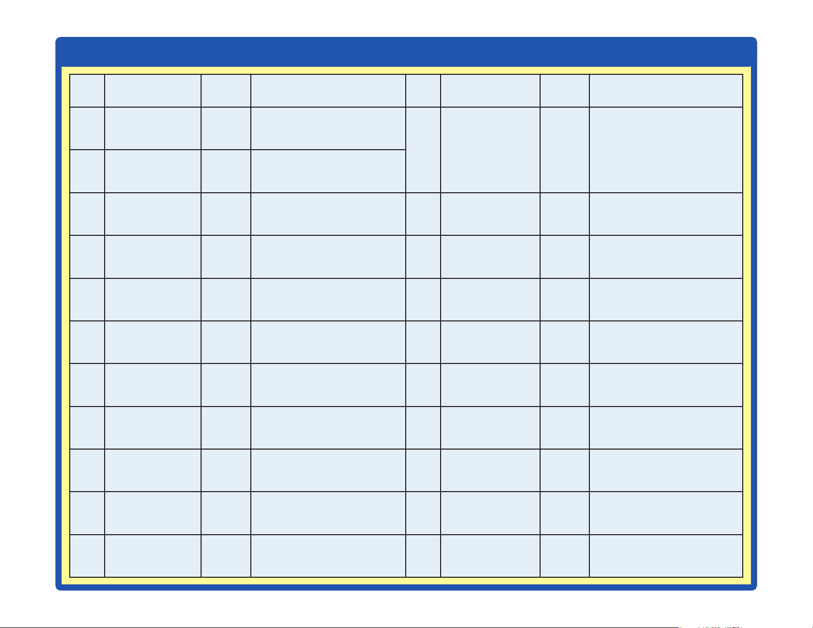
Parts List (Colors and styles may vary) Symbols and Numbers
Qty. ID Name Symbol Part # Qty. ID Name Symbol Part #
r 1
Base Grid
(11.0” x 7.7”)
6SCBG
r 1
Jumper Wire
(Black, 18”)
6SCJ1
r 2
1-Snap Wire 6SC01
r 1
Jumper Wire
(Red, 18”)
6SCJ2
r 6
2-Snap Wire 6SC02
r 1
Jumper Wire
(Orange, 8”)
6SCJ3A
r 3
3-Snap Wire 6SC03
r 2
Jumper Wire
(Blue, 4”)
6SCJ4
r 1
4-Snap Wire 6SC04
r 1
Programmable Fan 6SCM8
r 1
5-Snap Wire 6SC05
r 1
PNP Transistor 6SCQ1
r 1
Battery Holder - uses three (3)
1.5V type “AA” (not Included)
6SCB3
r 1
NPN Transistor 6SCQ2
r 1
Red Light Emitting
Diode (LED)
6SCD1
r 1
Slide Switch 6SCS1
r 1
Green Light Emitting
Diode (LED)
6SCD2
r 1
Press Switch 6SCS2
r 1
Red/Yellow Bicolor Light
Emitting Diode (LED)
6SCD10
r 1
Selector 6SCS8
r 1
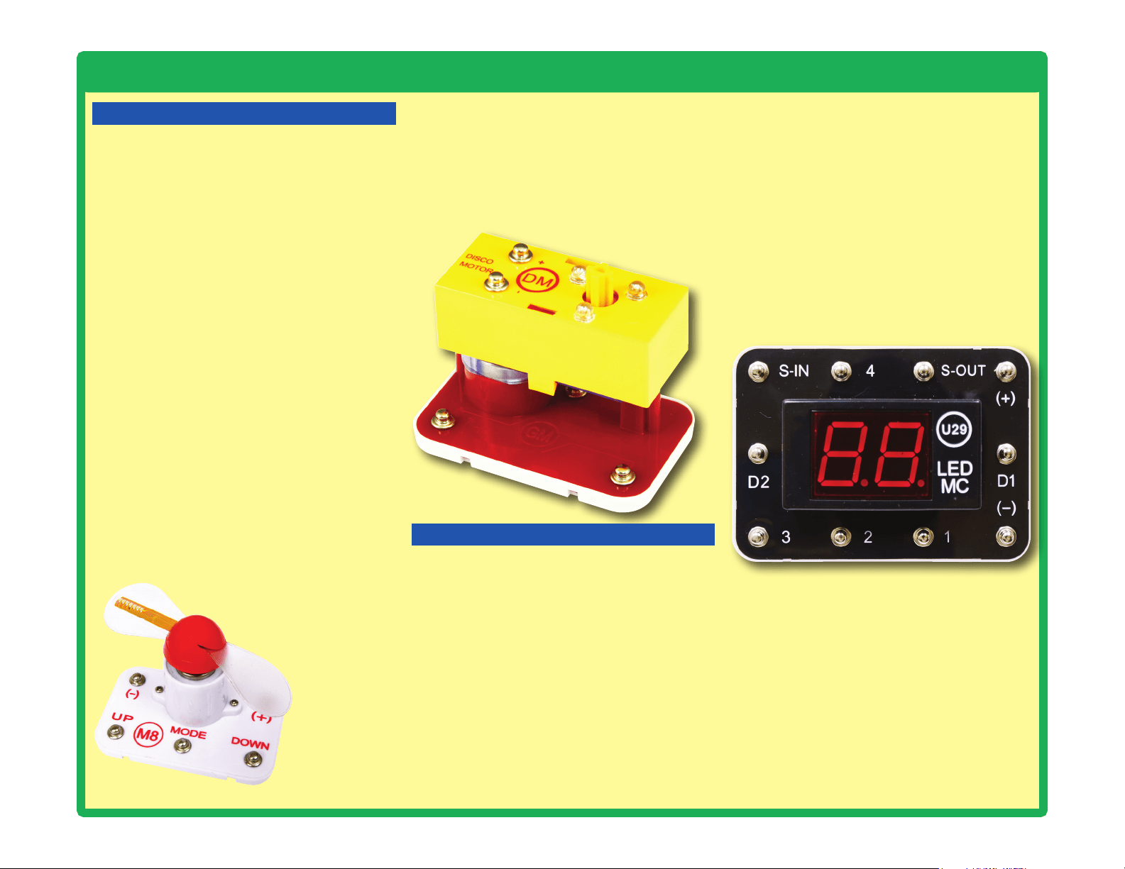
Disco Motor 6SCDM
r 1
Speaker 6SCSP2
r 1
Support Bar for Disco
Covers
6SCDMSB
r 1
Alarm IC 6SCU2
r 1
Disco Cover, Triangle 6SCDMCT
r 1
LED Display and
Microcontroller
6SCU29
r 1
Disco Cover, Hexagon
6SCDMCH
You may order additional / replacement parts at our website: https://www.elenco.com/replacement-parts/
5
4
3
2
1
U29
B3
DM
Q1
D10
D1
D2
U2
SP2
S8
S2
S1
Q2
M8

3
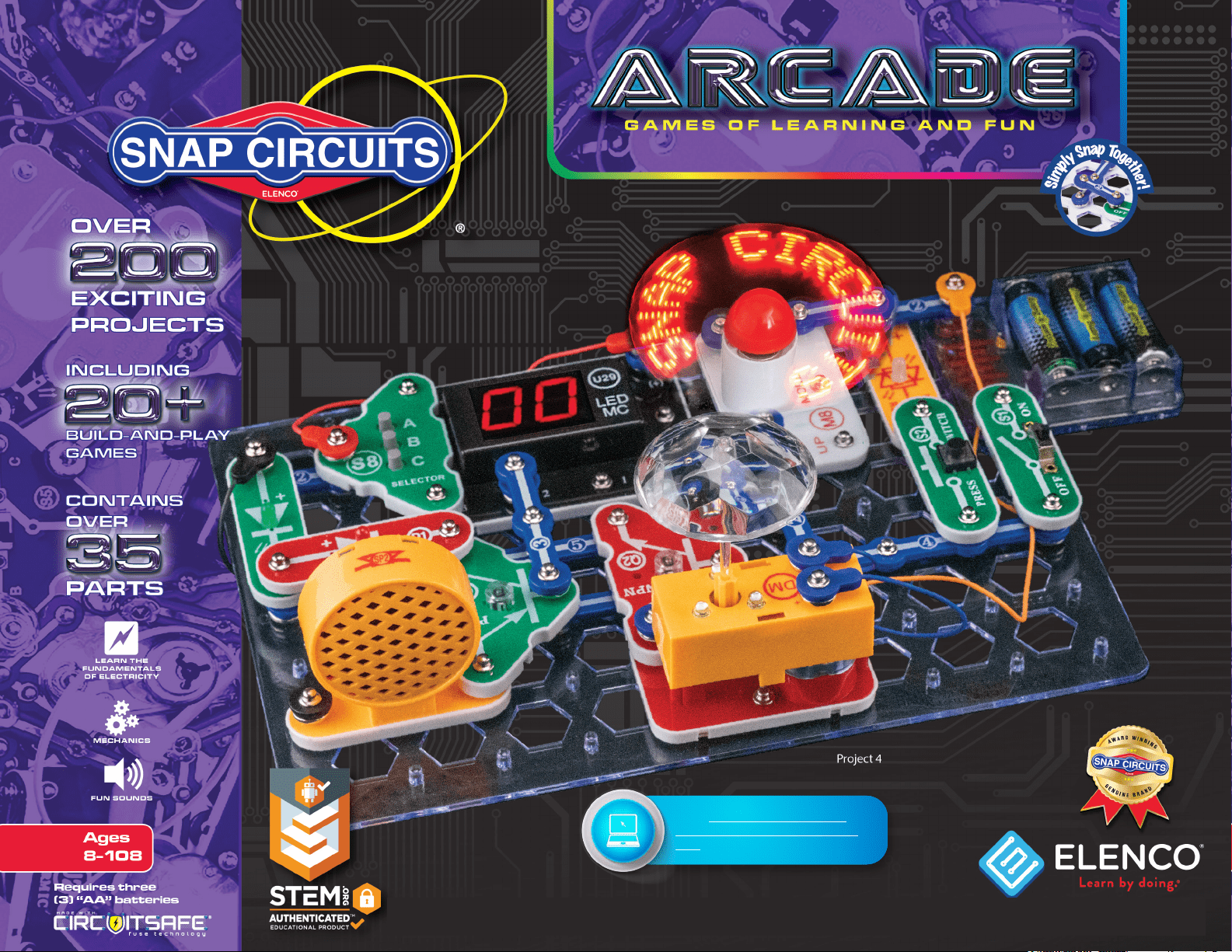
Snap Circuits
®
uses building blocks with snaps
to build the different electrical and electronic
circuits in the projects. Each block has a
function: there are switch blocks, light blocks,
battery blocks, different length wire blocks,
etc. These blocks are different colors and
have numbers on them so that you can easily
identify them. The blocks you will be using are
shown as color symbols with level numbers
next to them, allowing you to easily snap them
together to form a circuit.
For Example:
This is the slide switch, it is green and has
the marking on it. The part symbols in this
booklet may not exactly match the appearance
of the actual parts, but will clearly identify them.
This is a wire block which is blue and comes in
different wire lengths.
This one has the number , , ,
or on it depending on the length of the wire
connection required.
There is also a 1-snap wire that is used as a
spacer or for interconnection between different
layers.
You need a power source to build each circuit.
This is labeled and requires three (3) 1.5V
“AA” batteries (not included).
When installing a battery, be sure the spring
is compressed straight back, and not bent up,
down, or to one side.
A large clear plastic base grid is included with
this kit to help keep the circuit blocks properly
spaced. You will see evenly spaced posts that
the different blocks snap into. The base has
rows labeled A-G and columns labeled 1-10.
Next to each part in every circuit drawing is
a small number in black. This tells you which
level the component is placed at. Place all
parts on level 1 rst, then all of the parts on
level 2, then all of the parts on level 3, etc.
Some circuits use the jumper wires to make
unusual connections. Just clip them to the
metal snaps or as indicated.
The programmable fan (M8) displays
messages. You can change the messages
displayed using project 15.
Most projects that use the LED MC (U29)
require that you select a game using the
selector (S8). This is explained in the projects,
but here are a few notes:
● There are 21 games available.
●
If you try to select a game number higher
than 21 then the display will be reset to “00”.
● When the player wins, loses or nishes a
game, the display will say “Go” again and
the player can play the game again.
●
The only way to select a different game is by
turning off the circuit and then turning it back
on so that “00” appears on the display again.
Some projects have you mount one of the
disco covers on the disco motor (DM):
2
3
4
5
Note: While building the projects, be careful not
to accidentally make a direct connection across
the battery holder (a “short circuit”), as this may
damage and/or quickly drain the batteries.
How to Use Snap Circuits
®
B3
S1
Flat side
Flat side
DM
shaft
4
About Your Snap Circuits
®
Parts
(Part designs are subject to change without
notice).
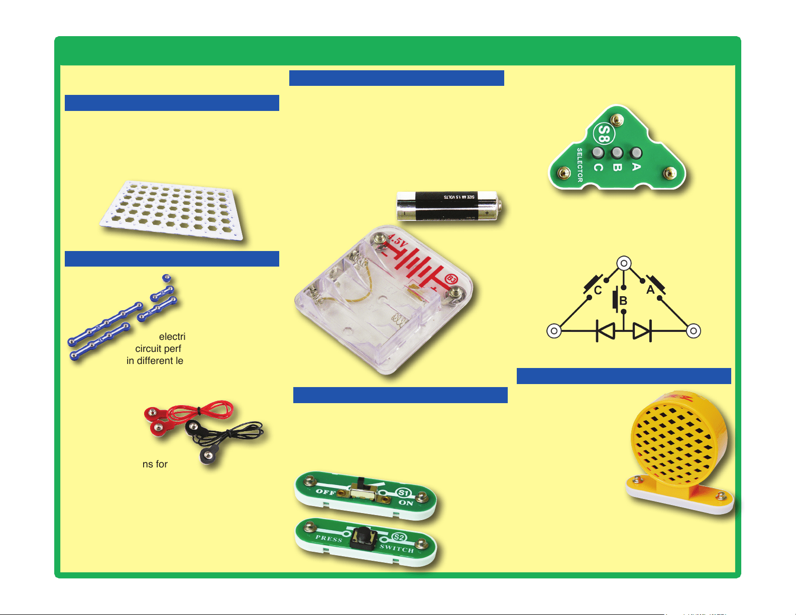
BASE GRID
The blue snap
wires are wires
used to connect
components. They
are used to transport
electricity and do not affect
circuit performance. They come
in different lengths to allow orderly
arrangement of connections on the
base grid.
The jumper
wires (red,
black, orange,
& blue) make
exible connections for
times when using the snap
wires would be difcult. They also are used to
make connections off the base grid.
Wires transport electricity just like pipes are
used to transport water. The colorful plastic
coating protects them and prevents electricity
from getting in or out.
BATTERY HOLDER
The base grid is a platform for mounting parts
and wires. It functions like the printed circuit
boards used in most electronic products, or like
how the walls are used for mounting the electrical
wiring in your home.
SNAP WIRES & JUMPER WIRES
The batteries (B3) produce an electrical voltage
using a chemical reaction. This “voltage” can
be thought of as electrical pressure, pushing
electricity through a circuit just like a pump
pushes water through pipes. This voltage is much
lower and much safer than that used in your
house wiring. Using more batteries increases
the “pressure”, therefore, more electricity ows.
Battery Holder (B3)
The selector (S8) is a more complex switch that
will often be used with the LED MC (U29).
Selector (S8)
Slide & Press
Switches
(S1 & S2)
SLIDE & PRESS SWITCHES
The slide & press switches (S1 & S2) connect
(pressed or “ON”) or disconnect (not pressed or
“OFF”) the wires in a circuit. When ON they have
no effect on circuit performance. Switches turn on
electricity just like a faucet turns on water from a pipe.
For people familiar with schematic diagrams, the
schematic for the selector looks like this:
The speaker (SP2)
converts electricity
into sound by making
mechanical vibrations.
These vibrations
create variations in air
pressure, which travel
across the room. You
“hear” sound when
your ears feel these air
pressure variations.
SPEAKER
Speaker (SP2)
5
About Your Snap Circuits
®
Parts
IN1
(–)
IN2
IN3
OUT
Connections:
IN1, IN2, IN3 - control inputs
(–) - power return to batteries
OUT - output connection
Connect control inputs to (+) power to make ve
alarm sounds, see project 59 for an example of
proper connections.
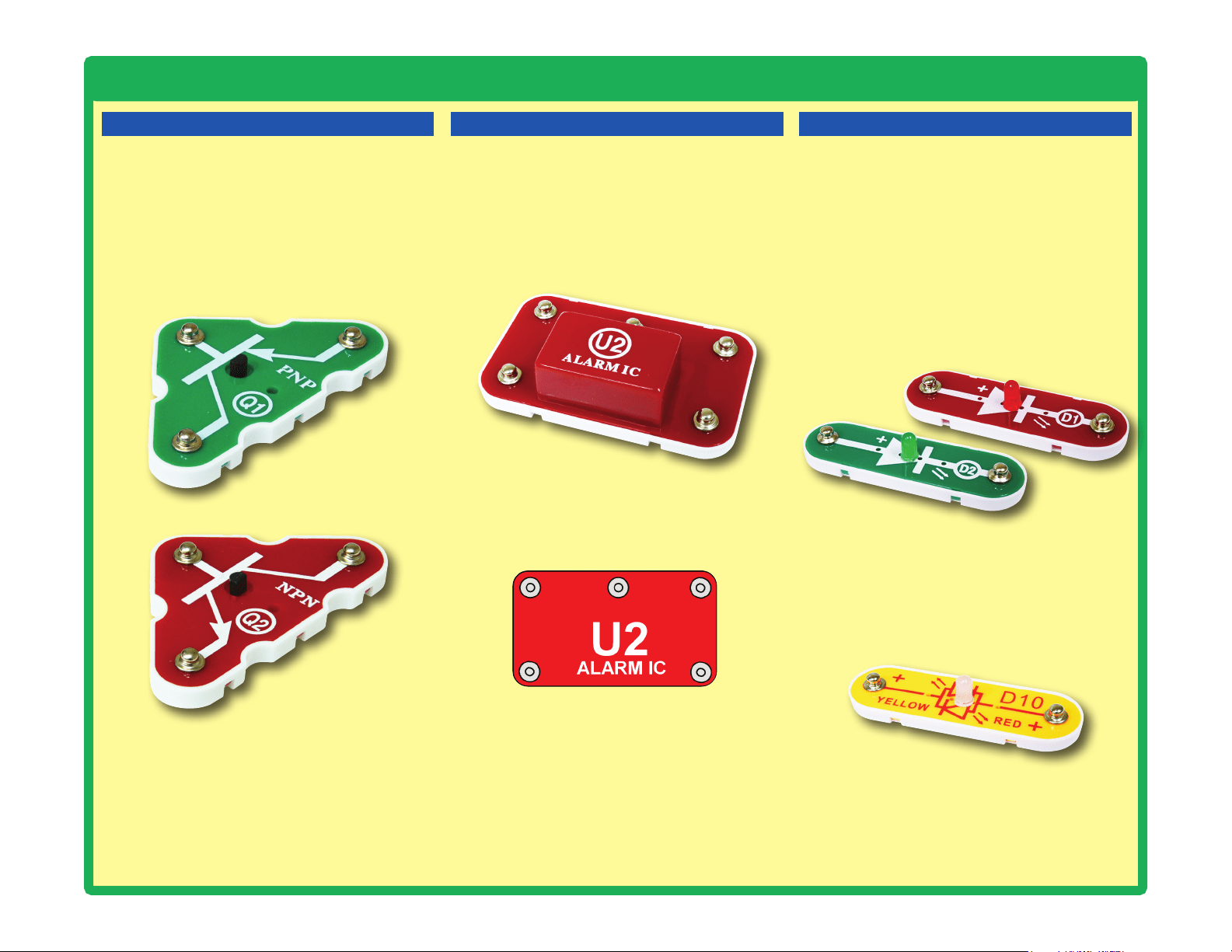
TRANSISTORS
The PNP & NPN transistors (Q1 & Q2) are
components that use a small electric current
to control a large current, and are used in
switching, amplier, and buffering applications.
They are easy to miniaturize, and are the main
building blocks of integrated circuits including
the microprocessor and memory circuits in
computers.
PNP & NPN Transistors (Q1 & Q2)
ALARM IC
The alarm IC (U2) contains a specialized sound-
generation integrated circuit (IC) and other
supporting components (resistors, capacitors,
and transistors) that are always needed with it.
A schematic for it is available at https://www.
elenco.com/faqs/.
Red & Green LEDs (D1 & D2)
Red/Yellow LED (D10)
The red/yellow LED (D10) is like the others but
has red and yellow LEDs connected in opposite
directions.
LEDs
The red & green LEDs (D1 & D2) are light
emitting diodes, and may be thought of as a
special one-way light bulb. In the “forward”
direction, (indicated by the “arrow” in the
symbol) electricity ows if the voltage exceeds a
turn-on threshold (about 1.5V for red and yellow,
about 2.0V for green, and about 3.0V for blue;
brightness then increases. A high current will
burn out an LED, so your Snap Circuits
®
LEDs
have internal resistors to protect them. LEDs
block electricity in the “reverse” direction.
Alarm IC (U2)
6
About Your Snap Circuits
®
Parts
MOTOR MODULES
Disco Motor (DM)
The programmable fan (M8) is a motor with
an LED circuit. A motor converts electricity into
mechanical motion, in the form of a spinning
shaft. In the light motor electricity is transported
through the motor shaft to power an LED circuit,
with LEDs mounted on the fan blade. The motor
spins in both directions, but the light circuit only
works in one direction.
How does electricity turn the shaft in the motor?
Electricity is closely related to magnetism,
and an electric current owing in a wire has a
magnetic eld similar to that of a very, very tiny
magnet. Inside the motor are three coils of wire
with many loops. If a large electric current ows
through the loops, the magnetic effects become
concentrated enough to move the coils. The
motor has a magnet inside, so as the electricity
moves the coils to align them with the permanent
magnet, the shaft spins.
The LEDs in the fan blade are flashed in a
pattern based on the programmed phrase, and
synchronized with the motor speed. The ashes
are precisely timed and are very brief, but your eyes
can’t react fast enough and the ashed pattern
gives the illusion of words oating in space. You
can change the messages displayed;
see project 15. UP, MODE, and
DOWN are controlled by
connecting those snaps to
(-) using switches or
the selector (S8).
The disco motor (DM) is a motor with a gearbox
attached to the shaft, and an LED module
mounted on it. The gearbox makes its shaft spin
slower but with more force than the shaft that is
directly attached to the motor, so it can spin the
disco covers. The LED module has red, green,
and blue LEDs, connected in parallel.
LED MC (U29):
(+) - Power from batteries
(—) - Power return to batteries
S-IN - Takes input from the selector (S8)
S-OUT - An output, often connected to an LED
1 - An output, often connected to an LED
2 - An output, usually connected to the speaker
3 - Takes input from the selector (S8)
4 - An output, often connected to an LED
D1 - Used to shut off the right LED display
D2 - Used to shut off the left LED display
LED MC (U29)
The Snap Circuits
®
Arcade page on our website
(https://shop.elenco.com/consumers/snap-
circuits-arcade.html) has additional information
about the LED MC, including a schematic
diagram, the program it is running, links to
software that will allow you to modify the program
or write your own programs for it, and how to
purchase a programming cable for it (which is
only needed if you want to reprogram it). The
microcontroller used is the PICAXE
®
08M2, which
has a special programming interface that makes
it easy to use. You can also nd information
about the PICAXE
®
08M2 from its manufacturer
at www.picaxe.co.uk.
LED DISPLAY & MICROCONTROLLER
The LED MC module (U29) has a dual 7-segment
LED display, a microcontroller, and supporting
parts. The microcontroller is a mini computer
which can be programmed to perform different
tasks, including monitoring things and making
things happen. It is pre-programmed for use with
the games projects. See project 17 for how to
select games on it.
LED MC outputs cannot control the motors in
the disco motor (DM) or programmable fan (M8)
directly, so an interface transistor must be used.
LED MC outputs can control your speaker (SP2)
and LEDs (D1, D2, D10, and the LEDs in the
disco motor) directly.
Programmable Fan (M8)
7
Summary of Games in the LED MC (U29)
# Name
Sample
Project
Description # Name
Sample
Project
Description
1
Arcade 4
Every few seconds it randomly turns on snaps
1, 4, & S-OUT, or plays a tune, or changes
the LED display. Used in many projects.
12
Home Run Derby
Game
26
A baseball “pitch” occurs where
the red, yellow and then green
LEDs light up in sequence but at
different speeds. You try to press
a button at the right moment to
“hit” the pitch.
2 Fast Arcade 5
Same as Game 1 but changes
faster.
3 Faster Arcade 5
Same as Game 2 but changes
even faster.
13 Baseball Game 27
Same as game 12, but has
“outs”.
4 Lucky Doubles 18
Rolls dice on the display, doubles
plays a winning tune.
14
Memory Game
(very easy)
64
A sequence of lights ash, and
you try to repeat the order by
pressing buttons.
5
Lucky Sixes,
Unlucky Ones
62
Rolls dice on the display, 66
plays a winning tune and 11
plays a losing tune.
15
Memory Game
(easy)
65
Same as game 14, but the
sequence is faster.
6 Risk & Reward 63
Game based on rolling dice on
the display.
16
Memory Game
(medium)
66
Same as game 14, but the
sequence is faster.
7 3 Second Hold 19
Timing game based on holding a
button down for 3 seconds.
17
Memory Game
(hard)
67
Same as game 14, but the
sequence is faster.
8 5 Second Hold 20
Same as Game 7 but for 5
seconds.
18
Memory Game
(progressive)
68
Same as game 14, but the
sequence gets faster as you play
it.
9 10 Second Hold 21
Same as Game 7 but for 10
seconds.
19 Twenty-One 28
A game based on the card game
Blackjack.
10 20 Second Hold 22
Same as Game 7 but for 20
seconds.
20
Binary Coded
Decimal
69
Uses LEDs to show how
numbers 1-7 can be displayed in
binary, which has only 2 states.
11
Numbers &
Letters
24
Cycles through letters & numbers
that can be shown on the display.
21 Changing Speed 25
Turns snaps 1 & 4 on/off at varying
speed. Snaps 1 & 4 are always in
opposite states. Used in many projects.
Projects 62-69 can be found online
8
Introduction to Electricity
What is electricity? Nobody really knows. We only know how to produce it,
understand its properties, and how to control it. Electricity is the movement of sub-
atomic charged particles (called electrons) through a material due to electrical
pressure across the material, such as from a battery.
Power sources, such as batteries, push electricity through a circuit, like a pump
pushes water through pipes. Wires carry electricity, like pipes carry water. Devices
like LEDs, motors, and speakers use the energy in electricity to do things. Switches
and transistors control the ow of electricity like valves and faucets control water.
Resistors limit the ow of electricity.
The electrical pressure exerted by a battery or other power source is called
voltage and is measured in volts (V). Notice the “+” and “–” signs on the battery;
these indicate which direction the battery will “pump” the electricity.
The electric current is a measure of how fast electricity is owing in a wire, just
as the water current describes how fast water is owing in a pipe. It is expressed
in amperes (A) or milliamps (mA, 1/1000 of an ampere).
The “power” of electricity is a measure of how fast energy is moving through a
wire. It is a combination of the voltage and current (Power = Voltage x Current). It
is expressed in watts (W).
The resistance of a component or circuit represents how much it resists the
electrical pressure (voltage) and limits the ow of electric current. The relationship
is Voltage = Current x Resistance. When the resistance increases, less current
ows. Resistance is measured in ohms (W), or kilo ohms (kW, 1000 ohms).
Nearly all of the electricity used in our world is produced at enormous generators
driven by steam or water pressure. Wires are used to efciently transport this
energy to homes and businesses where it is used. Motors convert the electricity
back into mechanical form to drive machinery and appliances. The most important
aspect of electricity in our society is that it allows energy to be easily transported
over distances.
Note that “distances” includes not just large distances but also tiny distances. Try
to imagine a plumbing structure of the same complexity as the circuitry inside a
portable radio - it would have to be large because we can’t make water pipes so
small. Electricity allows complex designs to be made very small.
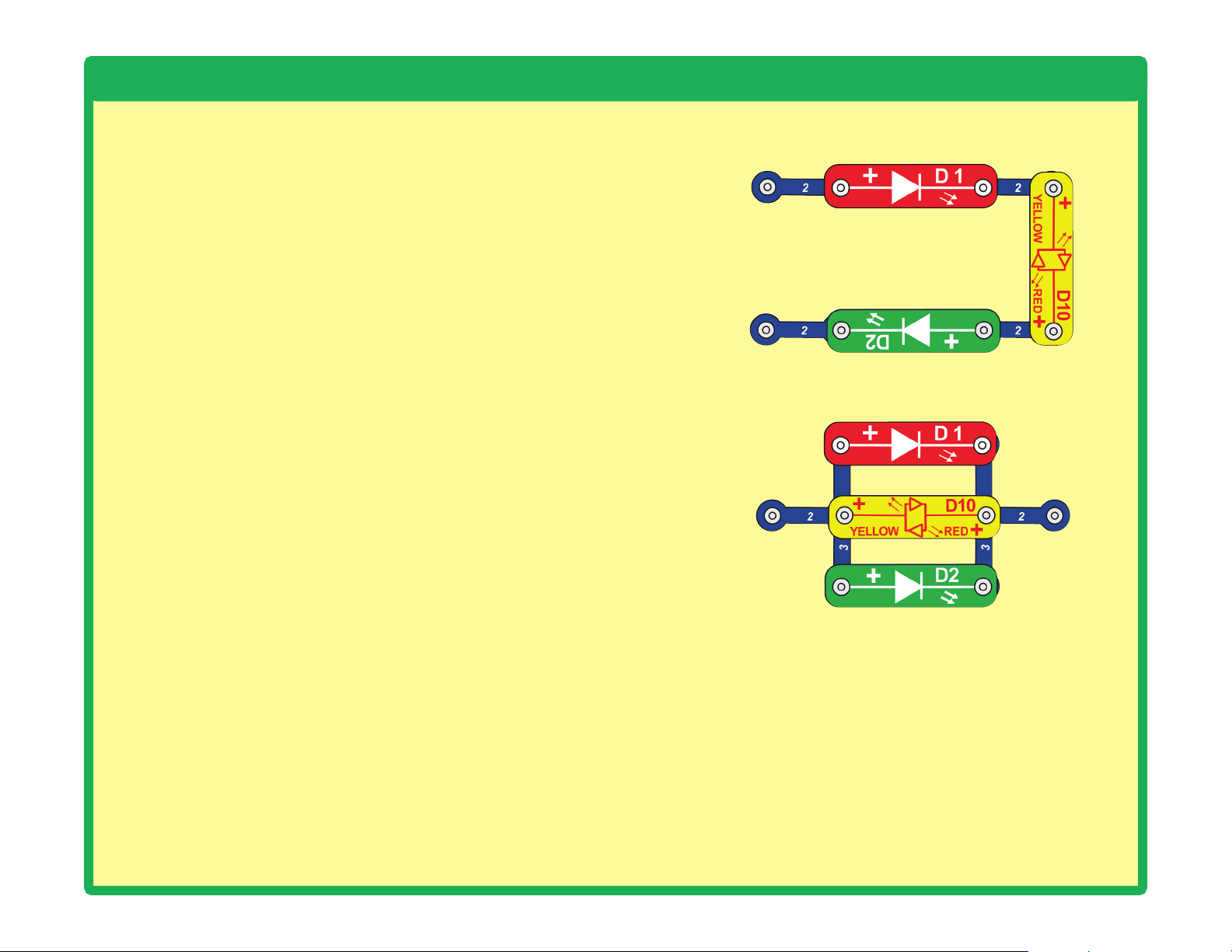
There are two ways of arranging parts in a circuit, in series or
in parallel. Here are examples:
Placing components in series increases the resistance; highest
value dominates. Placing components in parallel decreases
the resistance; lowest value dominates.
The parts within these series and parallel sub-circuits may be
arranged in different ways without changing what the circuit
does. Large circuits are made of combinations of smaller
series and parallel circuits.
Series Circuit
Parallel Circuit
9
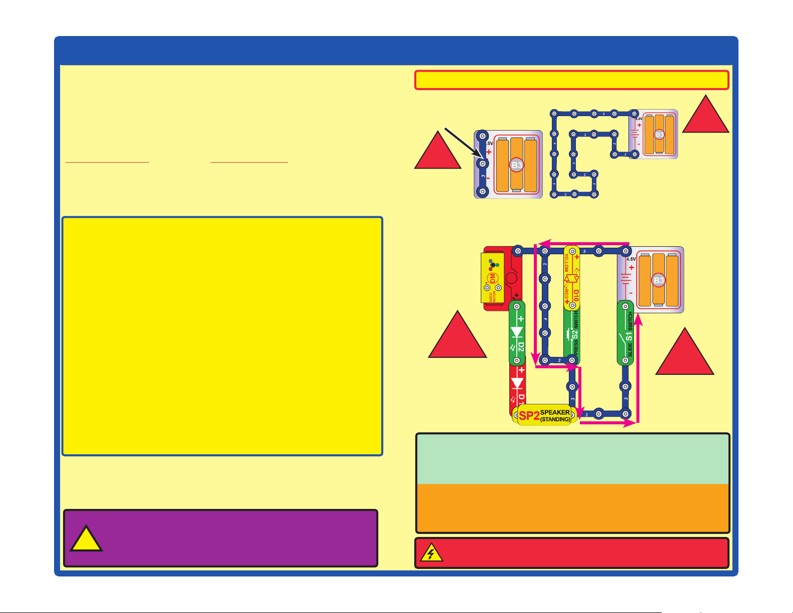
DOs and DON’Ts of Building Circuits
Placing a 3-snap wire directly
across the batteries is a
SHORT CIRCUIT.
This is also a
SHORT CIRCUIT.
When the slide switch (S1) is turned on, this large circuit has a SHORT
CIRCUIT path (as shown by the arrows). The short circuit prevents any
other portions of the circuit from ever working.
!
!
NEVER
DO!
NEVER
DO!
NEVER
DO!
!
NEVER
DO!
!
Warning to Snap Circuits
®
owners: Do not connect
additional voltage sources from other sets, or you may
damage your parts. Contact ELENCO
®
if you have questions
or need guidance.
!
Examples of SHORT CIRCUITS - NEVER DO THESE!!!
WARNING: SHOCK HAZARD - Never connect Snap Circuits
®
to the electrical outlets in your home in any way!
After building the circuits given in this booklet, you may wish to experiment on
your own. Use the projects in this booklet as a guide, as many important design
concepts are introduced throughout them. Every circuit will include a power
source (the batteries), a resistance (which might be a speaker, LED (which
has an internal protection resistor), motor, integrated circuit, etc.), and wiring
paths between them and back. You must be careful not to create “short circuits”
(very low-resistance paths across the batteries, see examples below) as this will
damage components and/or quickly drain your batteries. Only connect the ICs
using congurations given in the projects, incorrectly doing so may damage them.
Only connect the programmable fan (M8) using the congurations shown in the
projects, otherwise you may damage it or unintentionally erase all messages.
Elenco
®
is not responsible for parts damaged due to incorrect wiring.
Here are some important guidelines:
ALWAYS
USE EYE PROTECTION WHEN EXPERIMENTING ON YOUR OWN.
ALWAYS include at least one component that will limit the current
through a circuit, such as the speaker, an LED (which has an
internal protection resistor), ICs (which must be connected
properly), or motor (disco motor or programmable fan).
ALWAYS use switches in conjunction with other components that will
limit the current through them. Failure to do so will create a
short circuit and/or damage those parts.
ALWAYS disconnect your batteries immediately and check your wiring
if something appears to be getting hot.
ALWAYS check your wiring before turning on a circuit.
ALWAYS
connect ICs and the programmable fan (M8) using congurations
given in the projects or as per the connection descriptions for the parts.
NEVER connect to an electrical outlet in your home in any way.
NEVER leave a circuit unattended when it is turned on.
NEVER touch the programmable fan when it is spinning at high speed.
For all of the projects given in this book, the parts may be arranged in
different ways without changing the circuit. For example, the order of
parts connected in series or in parallel does not matter — what matters
is how combinations of these sub-circuits are arranged together.
You are encouraged to tell us about new circuits you create. If they are
unique, we will post them with your name and state on our website at
www.elenco.com/showcase.
Send your suggestions (with photos) to [email protected].
Elenco
®
provides a circuit designer so that you can make your own
Snap Circuits
®
drawings. This Microsoft
®
Word document can be
downloaded from www.elenco.com/for-makers.
10
Advanced Troubleshooting (Adult supervision recommended)
Elenco
®
is not responsible for parts damaged due to incorrect
wiring.
If you suspect you have damaged parts, you can follow
this procedure to systematically determine which ones
need replacing:
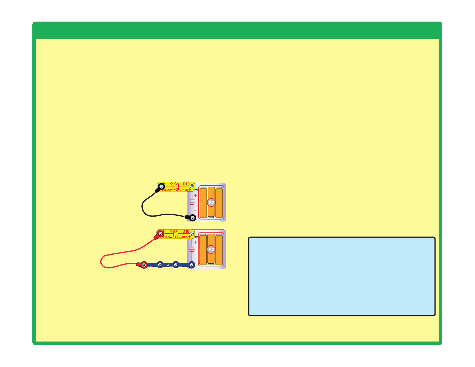
1. Red LED (D1), green LED (D2), red/yellow LED (D10),
speaker (SP2), and battery holder (B3): Place batteries in
holder. Place the red/yellow LED directly across the battery
holder in both directions, it should light red or yellow depending
on which side was positioned towards the battery “+” side. Do
the same for the red and green LEDs, but be sure to position
their “+” side towards the battery “+” side. “Tap” the speaker
across the battery holder contacts, you should hear static as it
touches. If none work, then replace your batteries and repeat,
if still bad then the battery holder is damaged.
2.
Jumper wires: Use this mini-
circuit to test each jumper wire,
the LED should light.
3. Snap wires: Use this mini-
circuit to test each of the snap
wires, one at a time. The LED
should light.
4. Slide switch (S1) and press switch (S2): Build project 1;
if the red LED (D1) doesn’t light then the slide switch is bad.
Replace the slide switch with the press switch to test it.
6.
Alarm IC (U2): Build project 59; you should hear a siren.
Variants 1, 2, 3, and 4 should change the sound, but the sound
for variant 4 may be the same as one of the others.
7.
PNP transistor (Q1): Use project 57 to test it.
8.
NPN transistor (Q2): Use project 58 to test it.
9.
Selector (S8): Use project 49 to test it.
10. Disco motor (DM): Build project 10. The shaft should spin,
and red, green, and blue LEDs should light.
11. Programmable fan (M8): Connect it as shown in project
15. It should slowly cycle through 6 phrases (unless you
erased all messages without programming in new ones). You
should be able to change the messages displayed using the
instructions in project 15.
Warning: If you erased all messages, then the part will not
display any messages until you program in new ones, as per
the instructions in project 15.
Note: After several hours of continuous use, the fan message
may be erratic, not clear, or even have no display. Turn off for
5 minutes, and it will be back to normal again.
12.
LED-MC (U29, the LED display & microcontroller): Use
project 52 to test it.
ELENCO
®
150 Carpenter Avenue
Wheeling, IL 60090 U.S.A.
Phone: (847) 541-3800
Fax: (847) 520-0085
e-mail: [email protected]
Website: www.elenco.com
You may order additional / replacement parts at:
https://www.elenco.com/replacement-parts/
11
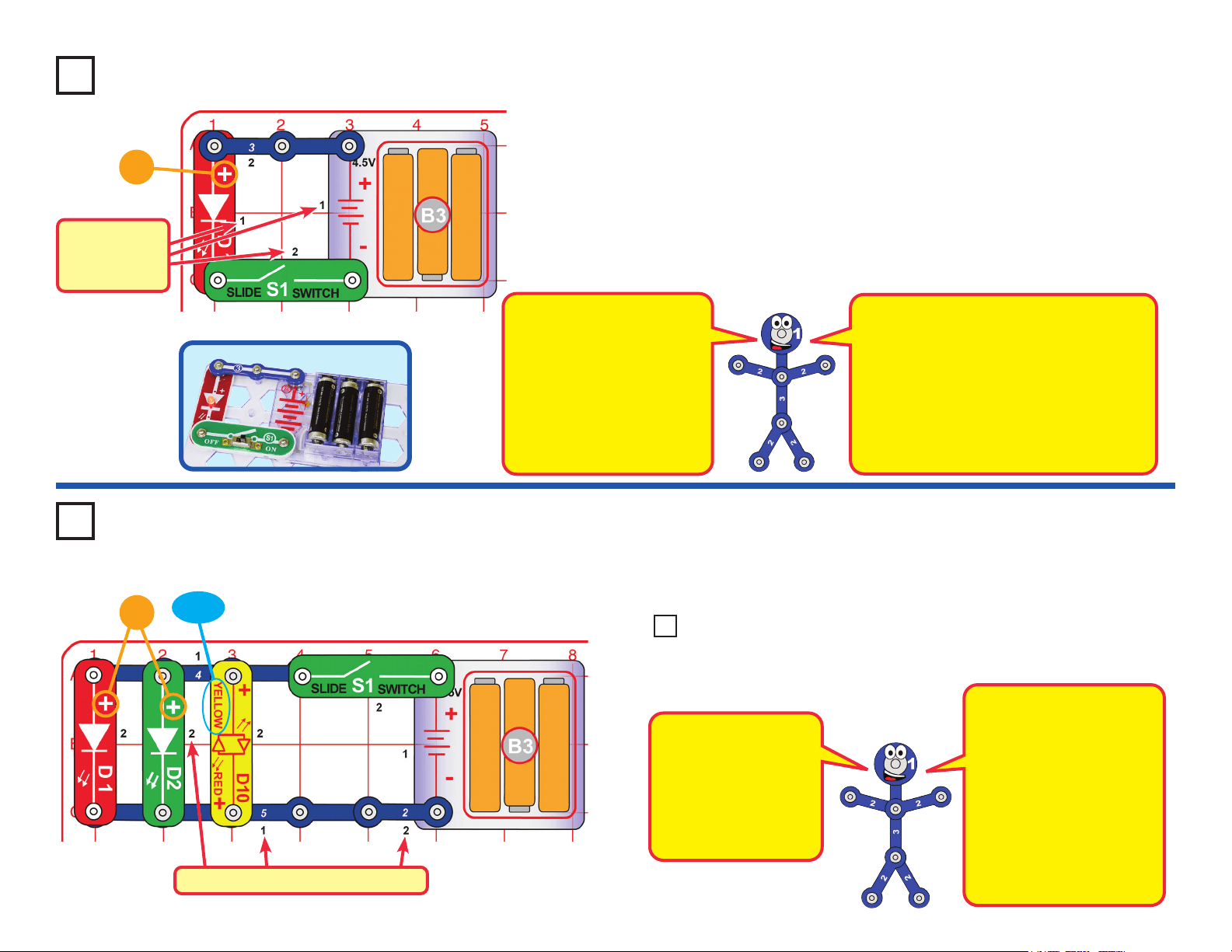
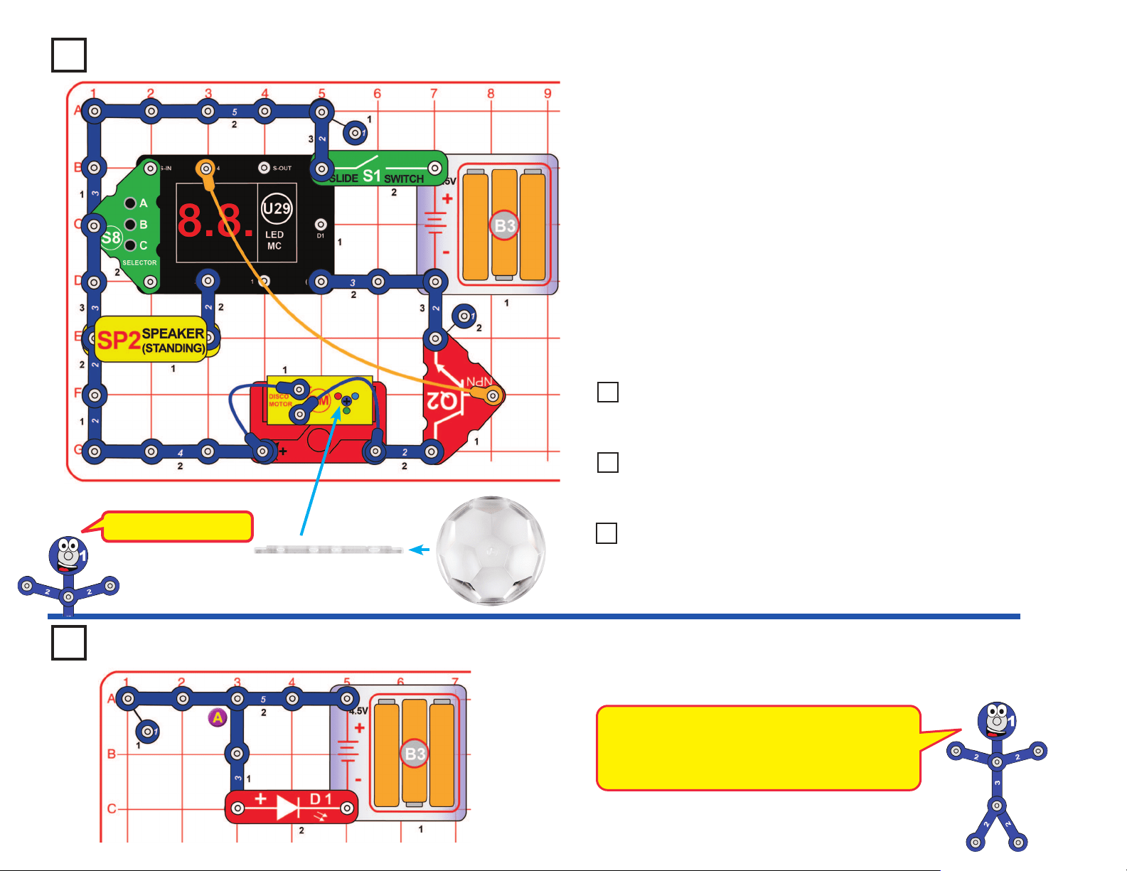
Project 1
Red Light
Snap Circuits
®
uses electronic blocks that snap onto a clear plastic grid to
build different circuits. These blocks have different colors and numbers on
them so you can easily identify them.
Build the circuit shown on the left by placing all the parts with a black 1
next to them on the board rst. Then, assemble parts marked with a 2.
Install three (3) “AA” batteries (not included) into the battery holder (B3) if
you have not done so already.
Turn on the slide switch (S1), and the red LED (D1) lights.
+
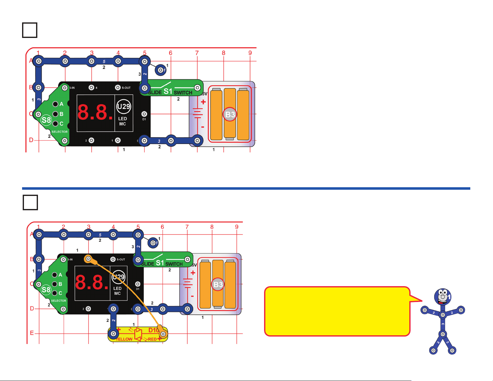
Project 2 Lights
Build the circuit shown here and turn on the slide switch (S1). The red,
green, and yellow LEDs (D1, D2, & D10) light.
+
YELLOW
Placement
Level
Numbers
Snappy says when you
turn on the slide switch,
electricity ows from the
batteries, through the
red LED and back to the
battery through the switch.
If the switch is off, the ow
of electricity is blocked, and
the red LED won’t light.
NOTE: this circuit (and many others
in this book) have an LED being used
without a resistor or other component
to limit the electric current through it.
Normally this could damage an LED but
your Snap Circuits
®
LEDs include internal
protection resistors, and will not be
damaged. Be careful if you later use other
electrical sets with unprotected LEDs.
Placement Level Numbers
Reversing the slide switch
and 2-snap wire has no
effect. LEDs only work in
one direction, so the red
& green LEDs do not work
in reverse, but the yellow
LED (D10) is a bi-color
LED, with separate red &
yellow LEDs in opposite
directions, as shown in its
symbol.
LEDs are light emitting
diodes, which convert
electrical energy into
light. The color of the
light depends on the
characteristics of the
material used in them.
Try reversing the position of the slide switch (S1), 2-snap wire, and
each of the LEDs (D1, D2, & D10), separately.
Project 3 Reverse Lights
12
Placement Level Numbers
Use the project 4 circuit but select game 2 or 3 (instead of
game 1). Some parts of the arcade show happen faster now,
such as the changing random pattern on the U29 LED display.
Use the project 4 circuit (with game 1, 2, or 3), but replace
the disco cover with the other one that is included. Place the
circuit in a dark room for best effects.
Build the circuit shown above by placing all the parts with a black 1 next to
them on the board rst. Then, place parts marked with a 2, and then parts with
a 3. Connect the jumper wires (red, black, orange, and blue) as shown in the
drawing. Install three (3) “AA” batteries (not included) into the battery holder
(B3) if you have not done so already. Place the disco cover support bar on the
disco motor (DM) shaft, and place one of the disco covers on it; note that both
sides of the support bar are “D-t”.
Turn on the slide switch (S1). The programmable fan (M8) spins, the red &
green LEDs (D1 & D2) light, and the display on the LED-MC (U29) displays
“00”. Push the press switch (S2) to light the yellow LED (D10).
Make the display on the LED-MC show “01” by pressing the A button on the
selector (S8) to increase the ones digit on the display. Press the B button on
the selector to select the game (now game 1), and a mini arcade show begins.
Every few seconds the speaker plays a tune while the disco motor spins &
lights, and/or the U29 LED display shows a random pattern.
If you want to change games then turn off S1 to reset the circuit. You can
make the sound louder by removing the disco motor and NPN transistor (Q2).
This circuit is shown on the
front of the Snap Circuits
®
Arcade box. Use that
picture to help in building it.
Project 4
Arcade
Disco Cover Assembly
+
YELLOW
Note: this is a 3-snap wire
connecting these points.
Disco Cover
SUPPORT BAR
DM
shaft
Flat side (“D-t”)
Flat side (“D-t”)
Disco Cover
Support Bar
Project 5 Fast Arcade Project 6 New Pattern Arcade
!
WARNING: Moving parts. Do not touch the fan or
motor during operation. Do not lean over the motor.
13
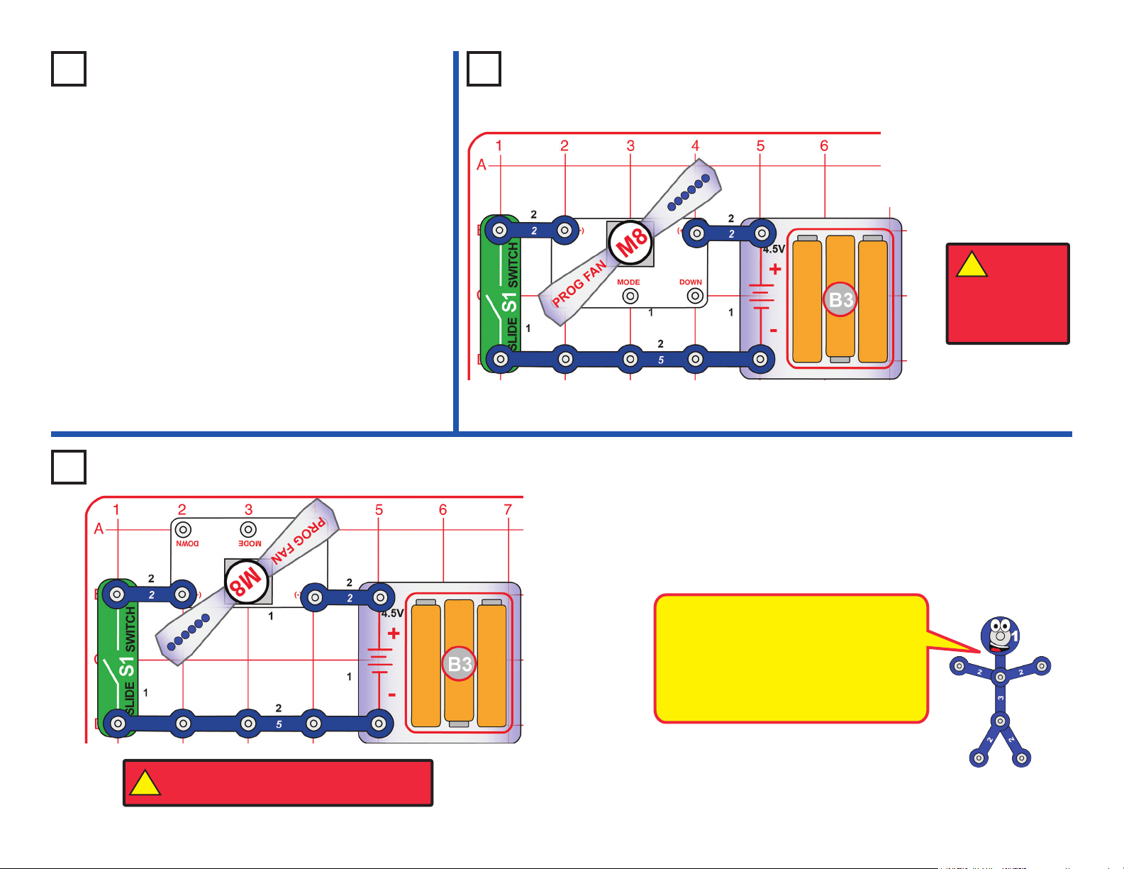
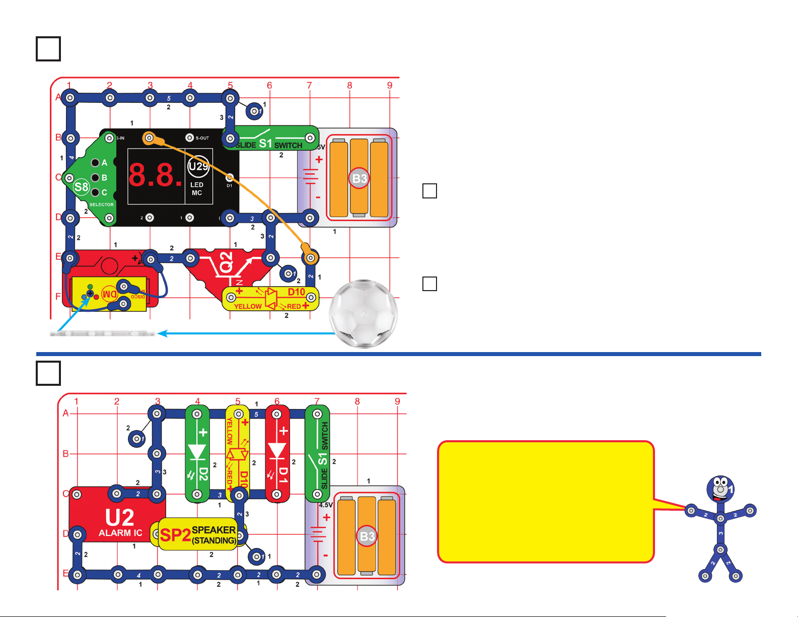
Project 8
Word Fan
Turn on the slide switch
(S1). The programmable
fan (M8) spins and slowly
displays messages. See
project 15 if you want to
change the messages.
Project 9
Just the Fan
Turn on the slide switch (S1). The programmable fan (M8) just spins,
without displaying any messages.
This circuit is like the Word Fan circuit
except the voltage to the programmable
fan is reversed. The motor works but
spins the fan in the opposite direction.
The lights on the fan are off, because
the microcircuit controlling them doesn’t
function when the voltage to it is reversed.
Use the project 4 circuit but select game 4 (instead
of game 1), then press button B. When the display
shows “Go” press button B to start the game.
• Hold down button C for a few seconds and
then release it.
• Two random digits from 1 to 6 will be shown
on the display (like rolling 2 dice).
• If the player rolls “doubles” (i.e. the two digits
are the same), a winning song will be played,
the disco motor (DM) spins & lights, and the
game starts over (“Go” is shown on the display
again).
• If the player does not roll “doubles”, then they
can keep trying by pressing button C again.
Project 7
Arcade Dice
!
WARNING: Moving parts. Do not touch the fan or
motor during operation. Do not lean over the motor.
WARNING:
Moving parts.
Do not touch the
fan or motor during
operation. Do not
lean over the motor.
!
14
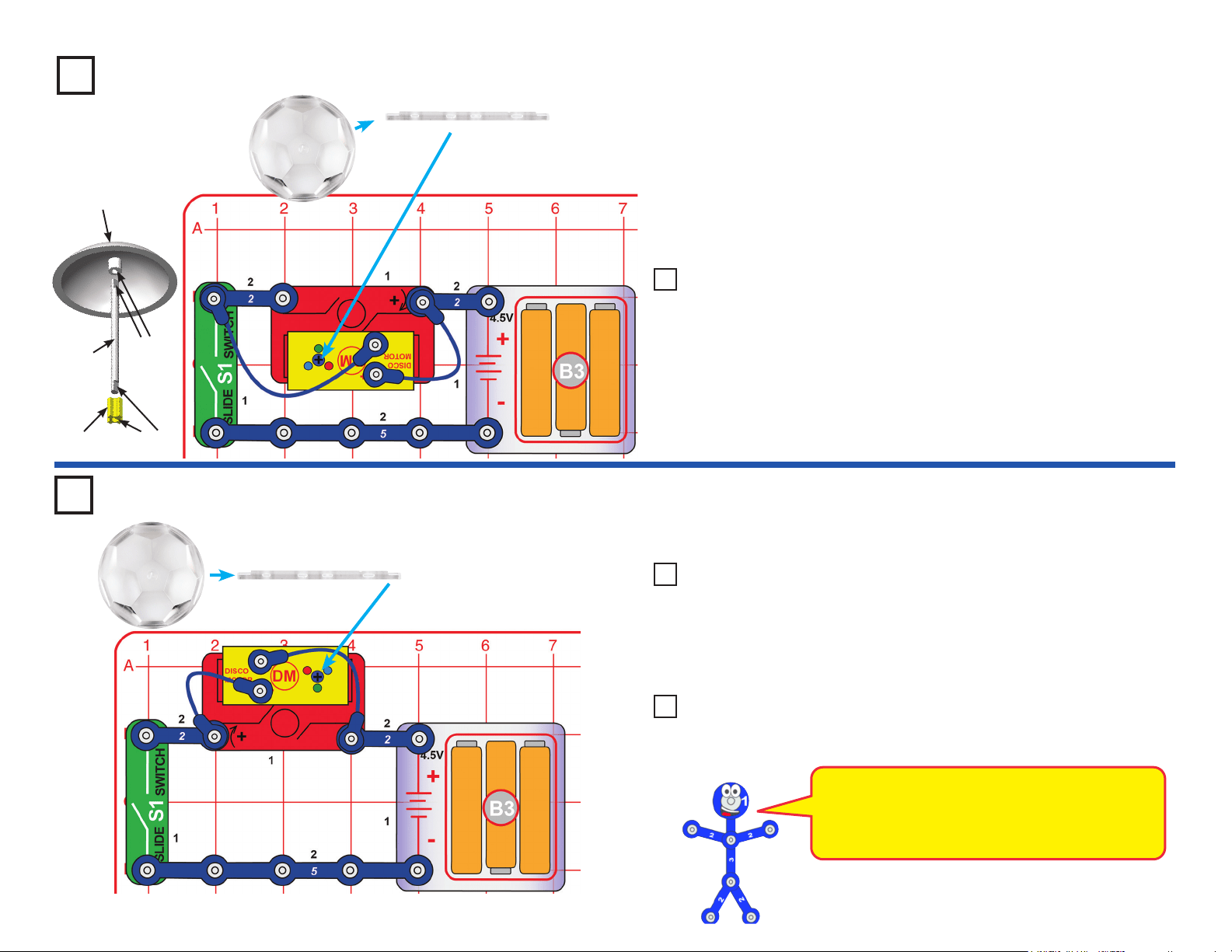
Project 10
Disco Ball
Build the circuit shown. Connect the two blue jumper wires to the snaps on
top of the disco motor (DM). Install three (3) “AA” batteries (not included)
into the battery holder (B3) if you have not done so already. Place one
of the disco covers on the disco motor shaft. Note that both sides of the
support bar are “D-t”.
Turn on the slide switch (S1) and watch the show. Place in a dark room
for best effects.
Project 12
This circuit is like project 10, but the disco cover spins in the opposite direction.
Flat side
(“D-t”)
DM
shaft
Flat side
(“D-t”)
Disco Cover
Support
Bar
Disco Cover
Assembly
Disco Cover
SUPPORT BAR
Disco Cover
SUPPORT BAR
Use any of the three preceding circuits, but replace the disco cover
with the other one included in this set. Compare the patterns on the
ceiling. Place in a dark room for best effects.
Use any of the project 10, 12, or 13 circuits, but remove the two blue
jumper wires. Now the lights do not work, so you just have a spinning
disco cover.
Project 13
Disco Ball with New Pattern
Project 14 Just the Ball
Use the preceding circuit, but remove the 2-snap wire between the
slide switch (S1) and disco motor (DM); connect the end of the blue
jumper wire directly to S1. Place in a dark room and look at the pattern
on the ceiling. The disco cover does not spin.
Project 11 Disco Pattern
Reverse Disco Ball
In this circuit we reversed the battery connections
to the disco motor (DM), so its shaft spins in the
opposite direction now. The connections to the
LEDs in the disco motor were not changed.
15
Project 15
Programmable Light Fan
Note that there is a 3-snap wire under the selector (S8) that is partially hidden. Turn on the
slide switch (S1). The programmable fan (M8) spins and slowly displays messages.
Button Functions in NORMAL MODE:
Button B (on S8) does nothing.
Erased messages can only be restored by re-entering them.
Button Functions in PROGRAM MODE:
Button B (on S8) does nothing.
Operation:
1. Use the slide switch (S1) to turn it on. The fan will display the message set last time. If it’s
the rst time, the fan will display the initial set (these are subject to change):
1 SNAP CIRCUITS 2 ARCADE 3 BY ELENCO
4 LEARN BY DOING 5 FUN ELECTRONICS 6 YOUR PHRASE
2. To program the messages, press the “DOWN” button to select the phase and program the
message as per the following steps:
• Press & hold the “MODE” button to enter the “PROGRAM MODE”. When the cursor is
blinking, you can edit the rst letter.
• Press the “UP” or “DOWN” button to nd the letter you want. Hold the button down to
change letters faster.
• Each phase can contain 15 letters. Press the “MODE” button to edit the next space.
• Press & hold the “MODE” button to save the message and exit from editing mode.
3. If you want to edit another message, press the “DOWN” button and select the phase and repeat the above steps.
4. In NORMAL MODE, press & hold the “UP” button to ERASE ALL MESSAGES. Turn off and on, it will not display any message until you program one.
5. Letters and marks available:
A B C D E F G H I J K L M N O P Q R S T U V W X Y Z
★ , : !? . () @
◦
# + — × ÷ = ≠ $ ¥ € ₵ ₤ £ & 1 2 3 4 5 6 7 8 9 0 ◼
Remark: “◼” means space.
Note: After several hours of continuous use, the fan message may be erratic, not clear, or even have no display. Turn off for 5 minutes, and it will be back to normal.
Button Controls Description
A (on S8) UP Press & hold to
ERASE ALL MESSAGES.
S2 MODE Press & hold to enter PROGRAM MODE.
C (on S8) DOWN Press to move to the next message.
Button Controls Description
A (on S8) UP
Press to nd the letter you want upwards. Press & hold to nd quickly.
S2 MODE
Press to move to the next space. Press & hold to save ready letters or exit.
C (on S8) DOWN
Press to nd the letter you want downward. Press & hold to nd quickly.
!
WARNING: Moving parts. Do not touch the fan or
motor during operation. Do not lean over the motor.
16
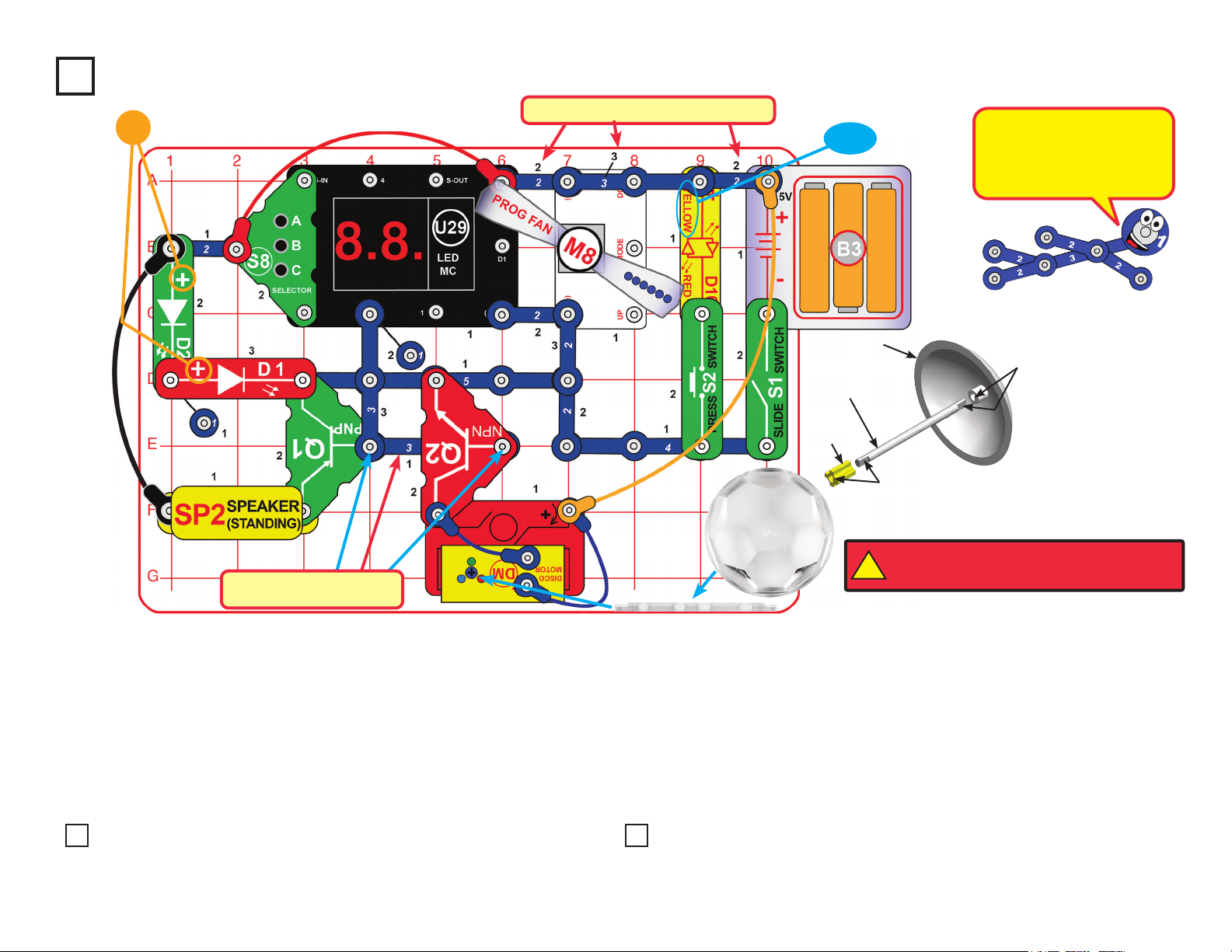
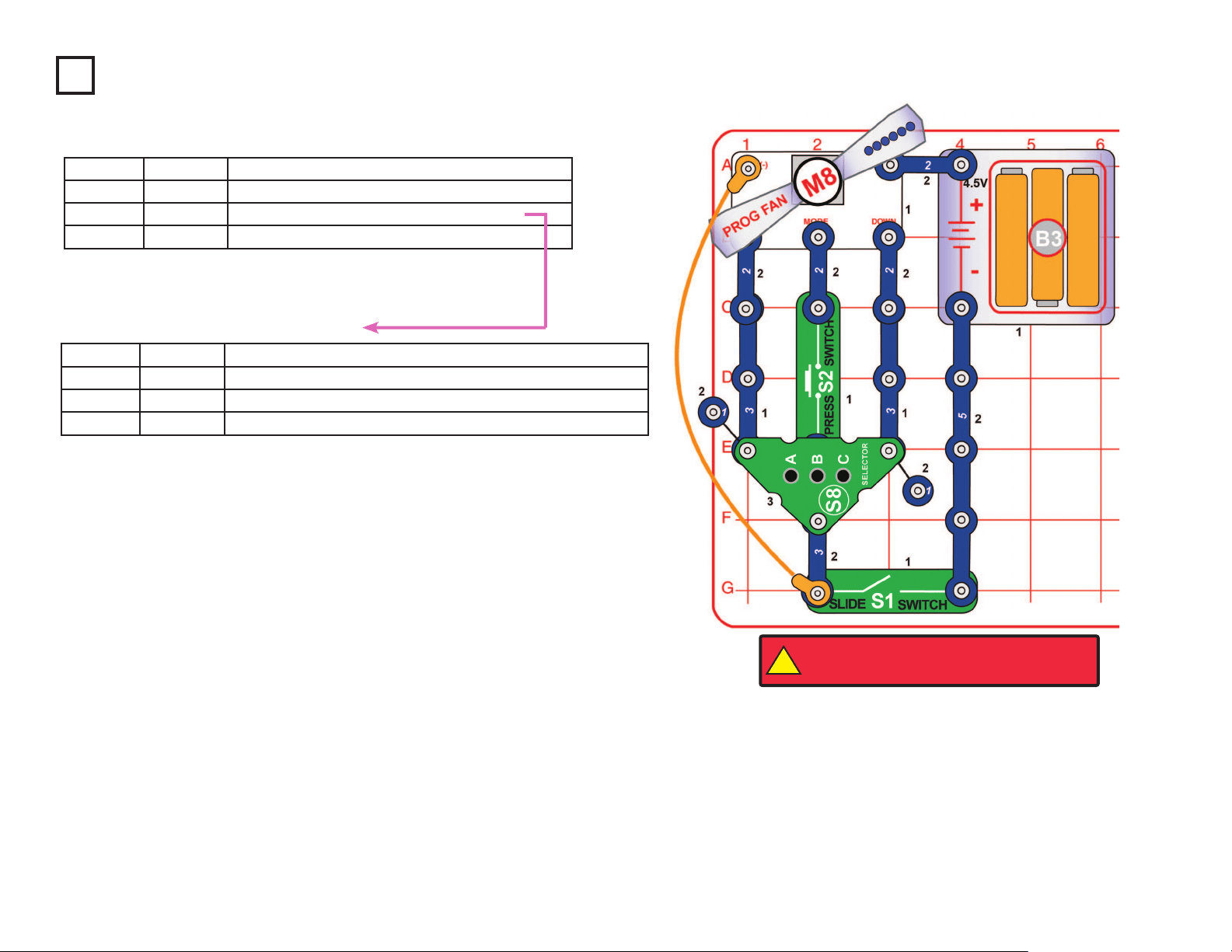
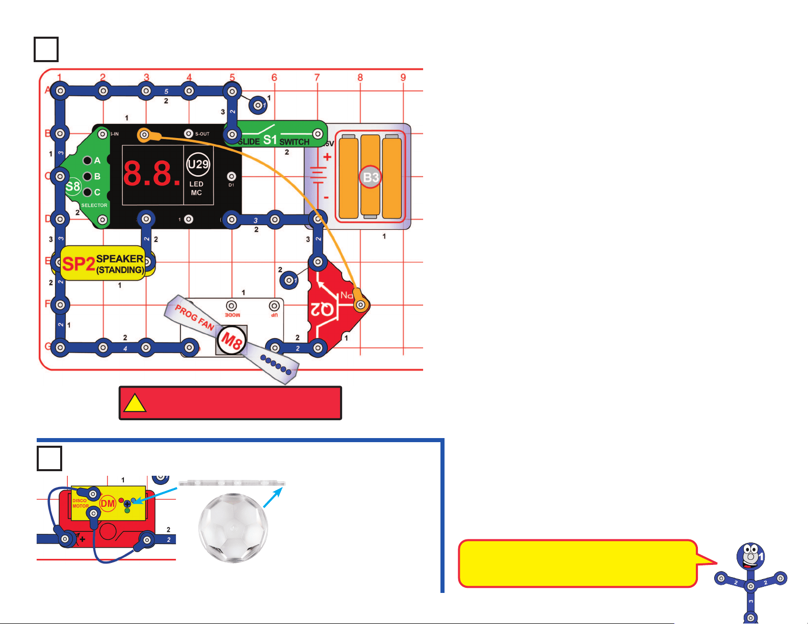
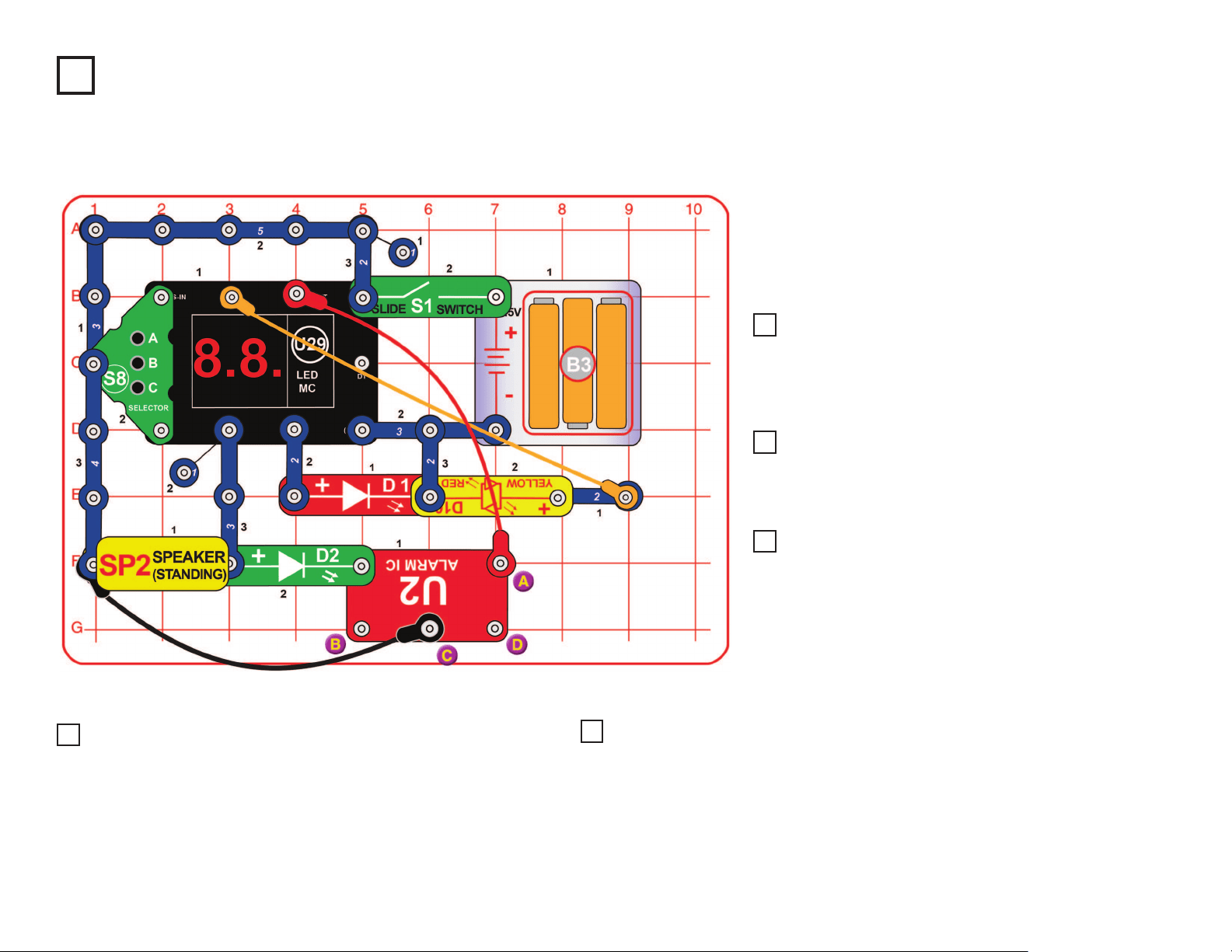
Project 16
Busy Circuit
Place one of the disco covers on the
disco motor (DM) shaft. Note that
both sides of the support bar are “D-
t”. Turn on the slide switch (S1). An
alarm sounds, the disco motor spins &
lights, the LEDs (D1, D2, & D10) light,
and the programmable fan spins and
displays a message. Push the press
switch (S2) several times to display
different messages. Place the circuit in
a dimly lit room for best effects.
Variants:
1. Change the alarm sound by
connecting the red jumper wire
across points X & Y, or X & Z.
2. Make the disco cover spin faster
by shifting the 2-snap wire across
points A & B to points B & C or
points B & D. The blue, orange,
& black jumper wires must stay
connected to the 2-snap wire.
This circuit has a lot
going on.
Disco Cover
SUPPORT BAR
!
WARNING: Moving parts. Do not touch the fan or
motor during operation. Do not lean over the motor.
17
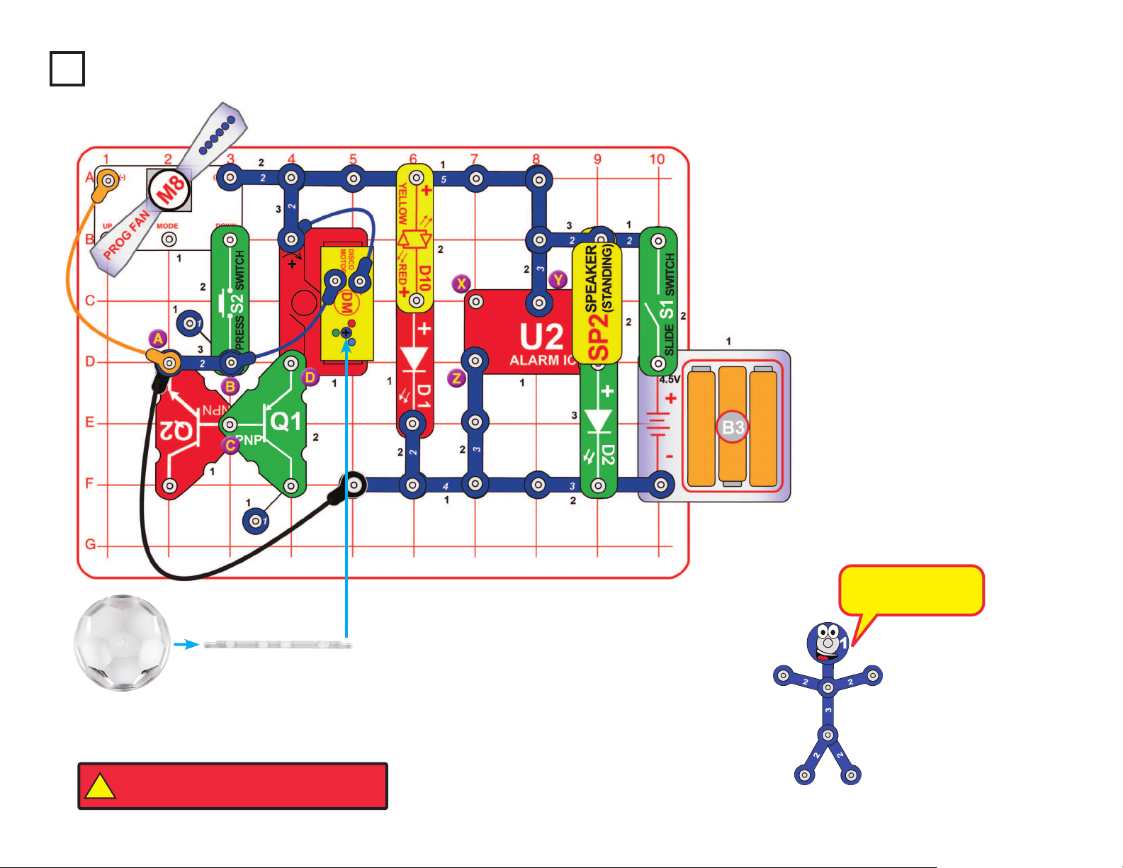
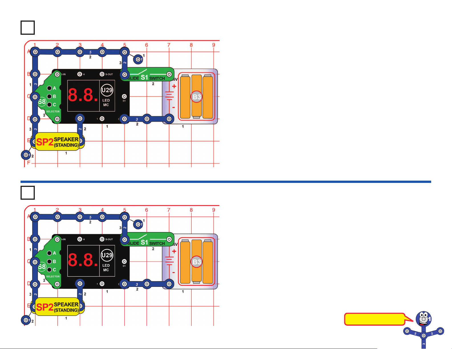
Project 17 Games Selector
Project 18 Lucky Doubles
Use this circuit but select Game 4 using the game selection procedure in
project 17.
Once the player selects Game 4 and sees “Go” on the display, then:
• Hold down button C for a few seconds and then release it.
• Two random digits from 1 to 6 will be shown on the display (like rolling
2 dice).
• If the player rolls “doubles” (i.e. the two digits are the same), a winning
song will be played and the game starts over (“Go” is shown on the
display again).
• If the player does not roll “doubles”, then they can keep trying by
pressing button C again.
• Have multiple people play to see who is the rst to roll “doubles”, or
who can roll the most “doubles” in 10 tries.
This simple circuit is intended as an introduction for how to select games
on the LED-MC (U29).
Turn on the slide switch (S1); the display on the LED-MC shows “00”.
Press the A button on the selector (S8) to increase the ones digit on the
display, and press the C button on the selector to increase the tens digit
on the display. When the display shows the game number you want, press
the B button on the selector to select it; you hear a beep and the display
shows “Go” for most games.
Notes:
• There are 21 games available, but most cannot be played with this
simple circuit, or would only have limited features.
• If you try to select a game number higher than 21, then the display will
be reset to “00”.
• When the player wins, loses, or nishes a game, the display will say
“Go” again and the player can play the game again.
• The only way to select a different game is by turning off the circuit and
then turning it back on so that “00” appears on the display again.
Now you are ready to play games!
This is a dice game.
18
Use this circuit but select Game 7 using the game selection procedure in
project 17.
Once the player selects Game 7 and sees “Go” on the display, then:
• Try to hold down button C for exactly 3 seconds, then release button C.
• The display will show the number of seconds the player held button C
down.
• If the player held button C down for 3 seconds, a winning song will play
while the disco cover spins, and the game starts over (“Go” is displayed
to play the game again). The disco cover will stop spinning when you
press C again.
• If the player held button C down for less than 3 seconds or more than
3 seconds, a losing song will play and the game starts over (“Go” is
displayed to play the game again).
• Play with multiple people to see who is the rst to hold the button for
exactly 3 seconds.
Project 19 3 Second Hold
Disco Cover
SUPPORT BAR
Use the same circuit and instructions, but select game 8, and try to hold down
button C for 5 seconds.
Use the same circuit and instructions, but select game 9, and try to hold down
button C for 10 seconds.
Project 20 5 Second Hold
Project 21 10 Second Hold
Use the same circuit and instructions, but select game 10, and try to hold down
button C for 20 seconds.
Project 22 20 Second Hold
Build the circuit as shown, then push on point A with your nger to
complete the circuit.
Project 23 Pressure Circuit
This is a timing game.
It may appear that the 3-snap and 5-snap wires
are touching, but they do not actually touch
unless you push them together.
19
Use this circuit but select Game 11 using the game selection procedure
in project 17.
Once the player selects Game 11 and sees “Go” on the display, then:
• Press button C, and a 0 is shown on the display.
• Press button C again, and a 1 is shown on the display.
• Continuing to press button C will cycle through the typical numbers
and letters that can be shown on the display.
• Not all the letters in the alphabet can be easily created on the display
since they are only 7-segment displays…can you identify which
letters are missing? One letter is skipped because a certain number
looks the same…can you identify what letter/number this is?
Project 24
Project 25 Bi-Color Light
Turn on the slide switch (S1); the display on the LED-MC (U29) shows
“00”. Press the A button on the selector (S8) to increase the ones digit on
the display, and press the C button on the selector to increase the tens
digit on the display. When the display shows “21”, press the B button on
the selector to start.
The red/yellow LED (D10) will be on continuously, but changing colors at
varying speed.
The red/yellow LED (D10) is a bi-color LED, which
means it has two LEDs (red & yellow) inside,
connected in opposite directions.
Notice that when D10 is changing colors quickly,
its red and yellow colors tend to blend into orange.
Numbers & Letters
20
Use this circuit but select Game 12 using the game selection procedure in
project 17.
Once the player selects Game 12 and sees “Go” on the display, then:
• Press & release button B, and the derby will begin.
• A baseball pitch occurs where the red, yellow, and then green LEDs light
up in sequence but at different speeds.
• The player needs to press button B at just the right time (after the green
LED is displayed) to hit a home run.
• If the player presses button B at just the right time, a winning song
will play, the crowd will cheer, and the display will increase to indicate
the number of home runs the player has. The next pitch will come
automatically.
• If the player presses button B at the wrong time (either too late or too
early), then a losing song will play and the display will ash the number
of outs (or misses) the player has for a few seconds, and then go back
to displaying the number of home runs the player has so far. The next
pitch will come automatically.
• Once the player gets 10 outs, a losing song will play, the total number of
home runs the player got is displayed for a few seconds, then the game
starts over (“Go” is displayed until the next player presses button B).
• See who can get the most home runs before getting 10 outs!
Alternate connections for speaker (a little louder):
Project 26
Home Run Derby Game
Use the same circuit and instructions, but select game 13, and try to
hold down button C for 5 seconds. The game plays the same way
except that each player gets 3 outs and then the game goes to the
next inning.
• Once the player gets 3 outs, a losing song will play, the total
number of home runs the player got in the inning is displayed for
a few seconds, then the game starts over to go to the next inning
(“Go” is displayed until the next player presses button B).
• Write down your scores after each inning and play a 9 inning game
to see who scores the most runs!
Project 27 Baseball Game
21
Use this circuit and select Game 19 using the game selection procedure
in project 17.
Once the player selects Game 19 and sees “Go” on the display, then:
● Press button C to get a rst playing card (all jacks, queens, and kings
are displayed as a 10). An Ace is displayed as an 11.
● The player then has the option to either:
◆ Press A to Stand – a winning or losing song will then play
depending on what the computer player gets:
► If the computer player “busts” (i.e. goes over 21), then a winning
song will play and the display will ash “Co” and then 22
indicating that the computer player went over 21. Then the game
starts over by displaying a new card.
► If the computer player has more points than the player, but not
greater than 21, then a losing song will be played and the display
will ash “Co” and the total points the computer player had. Then
the game starts over by displaying a new card.
► If the computer player has equal or less points than the player,
then a winning song will be played and the display will ash “Co”
and the total points the computer player had. Then the game
starts over by displaying a new card.
OR
◆ Press C to Hit – Another card will be drawn and the value will be
added to the previous card(s) value, and then:
► If the player “busts” (i.e. goes over 21), then a losing song will
play and the display will show the total value of all cards for a
few seconds. Then the game starts over by displaying a new
card.
► If the total value of all player cards is still 21 or less, then the
player must decide whether to Stand (press A) or take another
Hit (press C again).
► Note that Aces are treated as 11 points, unless the total value of
the cards exceeds 21, in which case Aces are treated as 1 point.
Sometimes you may see that your total reduced after you take a
Hit, which means you had an Ace that was being treated as 11,
but now is treated as a 1.
In the preceding circuit
you can replace the
programmable fan (M8)
with the disco motor
(DM), as shown here.
Project 28
Twenty-One
Project 29
Disco Cover
SUPPORT BAR
This game is based on the card game “Blackjack”.
You can use project 15 to program a Blackjack-
related phrase into the programable fan (M8).
!
WARNING: Moving parts. Do not touch the fan or
motor during operation. Do not lean over the motor.
Disco Twenty-One
22
Turn on the slide switch (S1); the display on the LED-MC
(U29) shows “00” and you hear a siren. Press the A button
on the selector (S8) once to make the display show “01”,
then press the B button on the selector to start.
Every few seconds one or more of the following will happen,
randomly changing: the red LED (D1) lights, the yellow
LED (D10) lights, the speaker plays a tune, the speaker
plays a siren, the green LED (D2) lights, and the U29 LED
display shows a random pattern.
Project 30 Siren Arcade
Use the preceding circuit (no need to reset the
LED-MC), but add a connection between the points
marked B & C using a blue jumper wire. The sound is
different now.
Use the preceding circuit, but remove the connection
between B & C, and add a connection between C & D.
The sound is different now.
Project 31 Siren Arcade (II)
Project 32 Siren Arcade (III)
Use the preceding circuit, but remove the connection
between C & D, and add a connection between A & D.
The sound is different now.
Use the project 30 circuit, but connect the end of the
black jumper wire to point D instead of point C. The
sound is different now.
Project 33 Siren Arcade (IV)
Project 34 Siren Arcade (V)
Use any of the ve preceding circuits, but turn off the slide switch (S1) to reset
the LED-MC (U29). Turn on the slide switch; the display on the LED-MC shows
“00”. Press the A button on the selector (S8) two or three times to increase the
ones digit on the display. When the display shows “02” or “03”, press the B button
on the selector to start.
The circuit works the same, except that it changes faster (“03” is faster than “02”).
Project 35 Fast Siren Arcade
23
Project 36
Disco Cover
SUPPORT BAR
Turn on the slide switch (S1); the display on the LED-MC (U29) shows
“00”. Press the A button on the selector (S8) to increase the ones digit on
the display, and press the C button on the selector to increase the tens
digit on the display. When the display shows “21”, press the B button on
the selector to start.
The red/yellow LED (D10) will be blinking at varying speed, and the disco
motor (DM) will be spinning at varying speed. For best effects, view in a
dark room.
Use the preceding circuit, but reverse the red/yellow LED (D10), or
replace it with the red LED (D1, “+” on right), green LED (D2, “+” on
right), or the speaker (SP2).The circuit works the same way but now it
sounds like a machine gun.
Use the project 36 circuit, but replace the disco motor (DM), including
the blue jumper wires to it, with the speaker (SP2).
Project 37
Variable Disco Speed Variants
Project 38
Loud Click Rate Changer
Turn on the slide switch (S1). Three LEDs are ashing and you hear a
machine gun sound.
Project 39 Tri-Light Machine Gun
The lower-right snap of the alarm IC is like an
electrical gate, opening and closing quickly to
let small bursts of electric current ow in. The
bursts of electric current also ow through
the green, yellow, & red LEDs (lighting them)
and the speaker (which produces sound).
The alarm IC produces the different siren
sounds by adjusting the pattern of current
bursts through the speaker.
Variable Disco Speed
24
Turn on the slide switch (S1); the display on the LED-MC (U29) shows
“00”. Press the A button on the selector (S8) to increase the ones digit on
the display, and press the C button on the selector to increase the tens
digit on the display. When the display shows “21”, press the B button on
the selector to start.
The red/yellow LED (D10) will be on continuously, but changing colors
at varying speed. The red & green LEDs (D1 & D2) will be alternately
between on and off, opposite each other, and synchronized with D10.
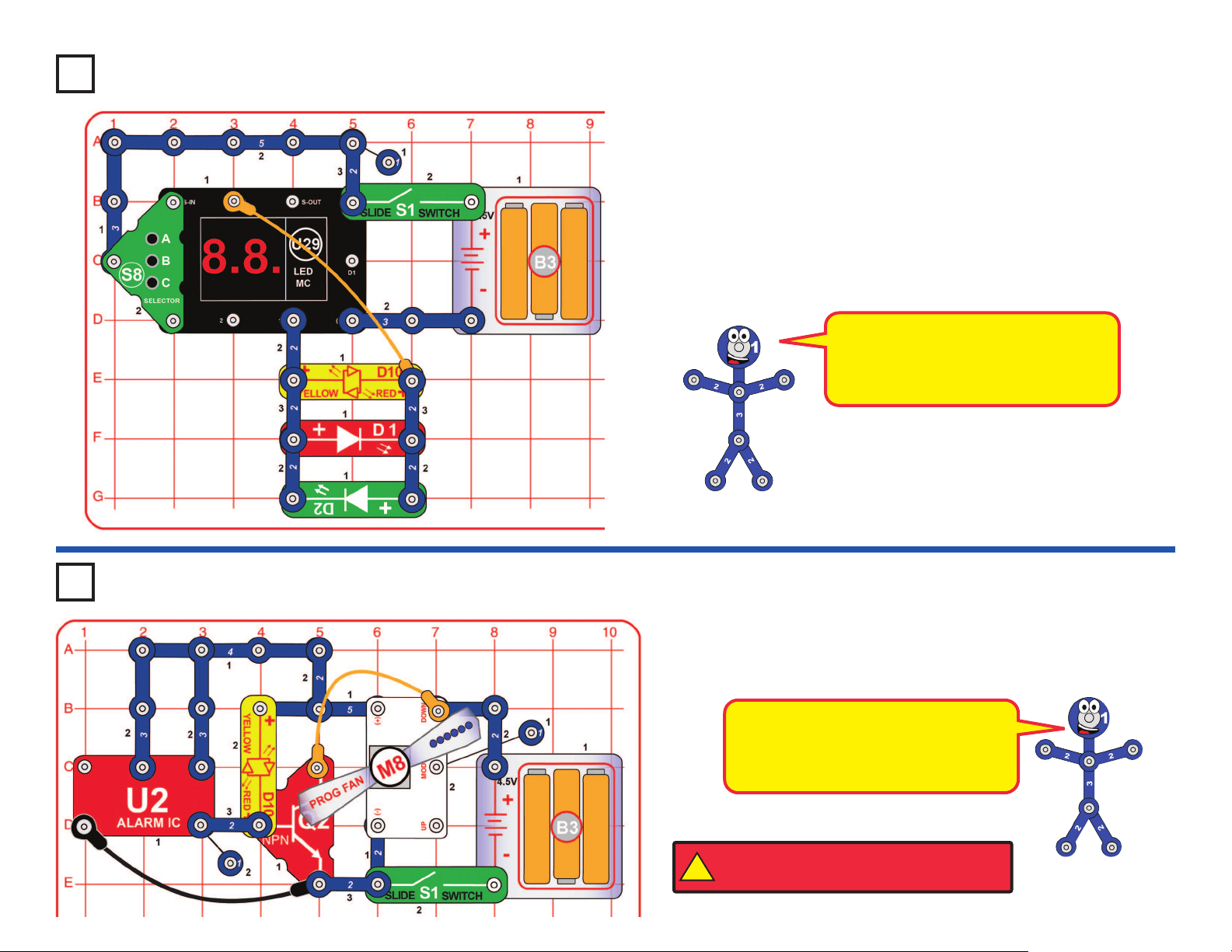
Turn on the slide switch (S1). The programmable fan (M8) spins, and
changes the phrase displayed about once a second. See project 15 to
change the phrases displayed.
Project 40
Dual Bi-Color Lights
Fast Phrase Changer
This circuit uses the alarm IC (U2) to
control the programmable fan (M8),
cycling through the six phrases stored
in it faster than normal.
!
WARNING: Moving parts. Do not touch the fan or
motor during operation. Do not lean over the motor.
Project 41
The red & green LEDs together act
as a bi-color LED. Compare them to
the red/yellow LED, which is a true bi-
color LED.

25
Turn on the slide switch (S1); the display on the LED-MC (U29) shows
“00”. Press the A button on the selector (S8) to increase the ones digit on
the display, and press the C button on the selector to increase the tens
digit on the display. When the display shows “21”, press the B button on
the selector to start.
Strange sounds will be heard on the speaker (SP2).
Project 42
Funky Siren
Use the preceding circuit, but add a connection between the points
marked B & C using a 1-snap and a 2-snap. The sound is different now.
Use the preceding circuit, but remove the connection between B & C,
and add a connection between C & D. The sound is different now.
Project 43 Funky Siren (II)
Project 44 Funky Siren (III)
Use the preceding circuit, but remove the connection between C & D,
and add a connection between A & D. The sound is different now.
Project 45 Funky Siren (IV)
Use the project 42 circuit, but remove the connection between C & E,
and add a connection between D & E using a blue jumper wire. The
sound is different now.
Project 46 Funky Siren (V)
Turn on the slide switch (S1); the display on the LED-MC (U29) shows
“00”. Press the A button on the selector (S8) to increase the ones digit on
the display, and press the C button on the selector to increase the tens
digit on the display. When the display shows “21”, press the B button on
the selector to start.
The “2” in the display will be toggling on/off at a varying rate.
Project 47
Vibrato 2
Use the preceding circuit, but add a second blue jumper between
points A & B. Now both digits on the display are toggling, but opposite
to each other.
Project 48 Vibrato 21
The LED MC (U29) is turning on the alarm
IC (U2) in short bursts, and varying their duration.
26
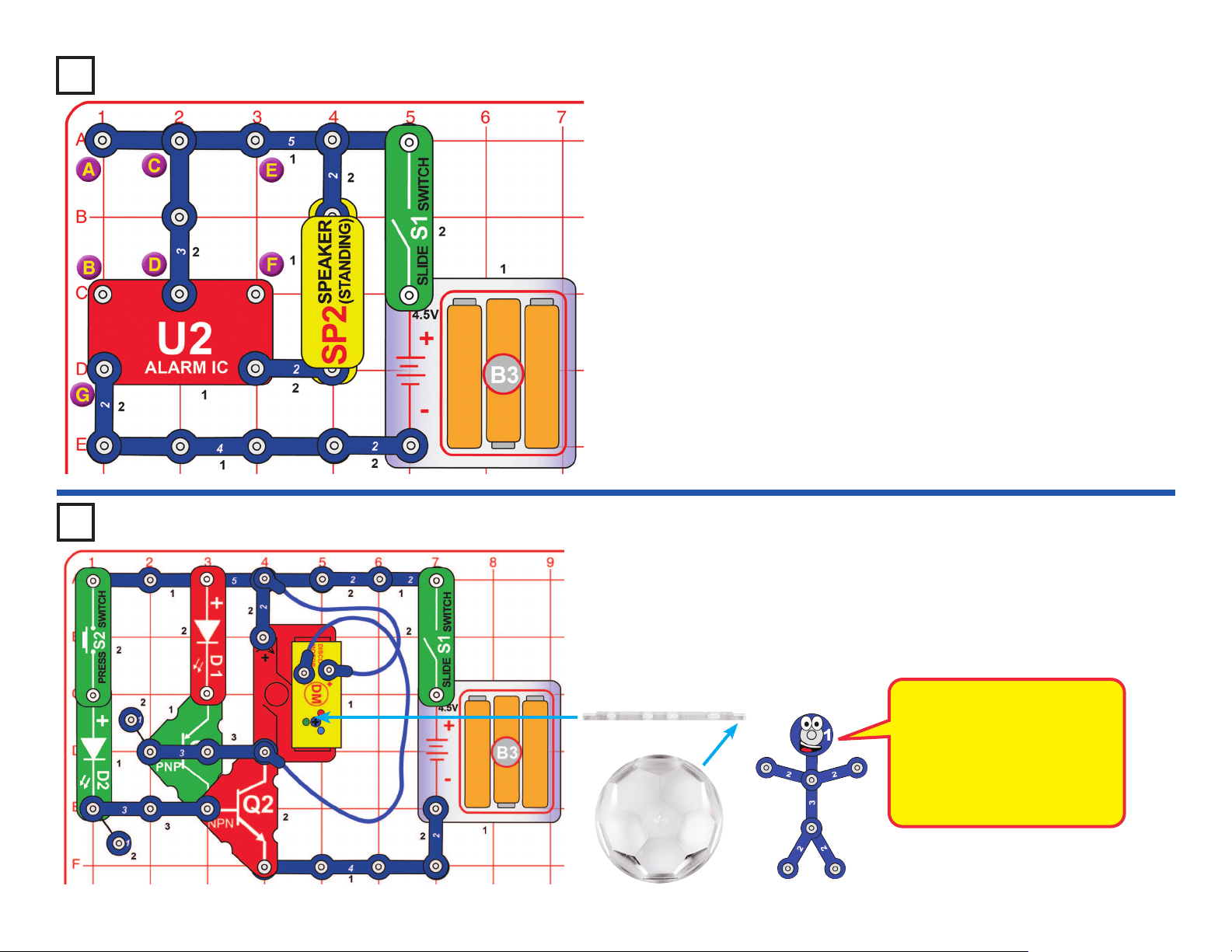
Project 52
LED-MC Test
Turn on the slide switch (S1); the display on the
LED MC (U29) should show “00”. Select game 1 by
pressing the A button on the selector (S8), then the
B button.
Every 2 seconds one or more of the following will
happen, randomly changing: D1 lights, D2 lights,
D10 lights, SP2 plays a tune, the U29 LEDs display
a random pattern. Make sure that eventually all
these parts are being controlled. If not, something
is wrong. Also, pushing the press switch (S2)
should turn off the LED display on U29 until you
release S2.
If desired, you can speed things up by turning S1
off and on (to reset the circuit), then selecting game
2 or game 3 by pressing the A button on S8, then
the B button. The tunes played on the speaker
(SP2) will play at the same speed as before.
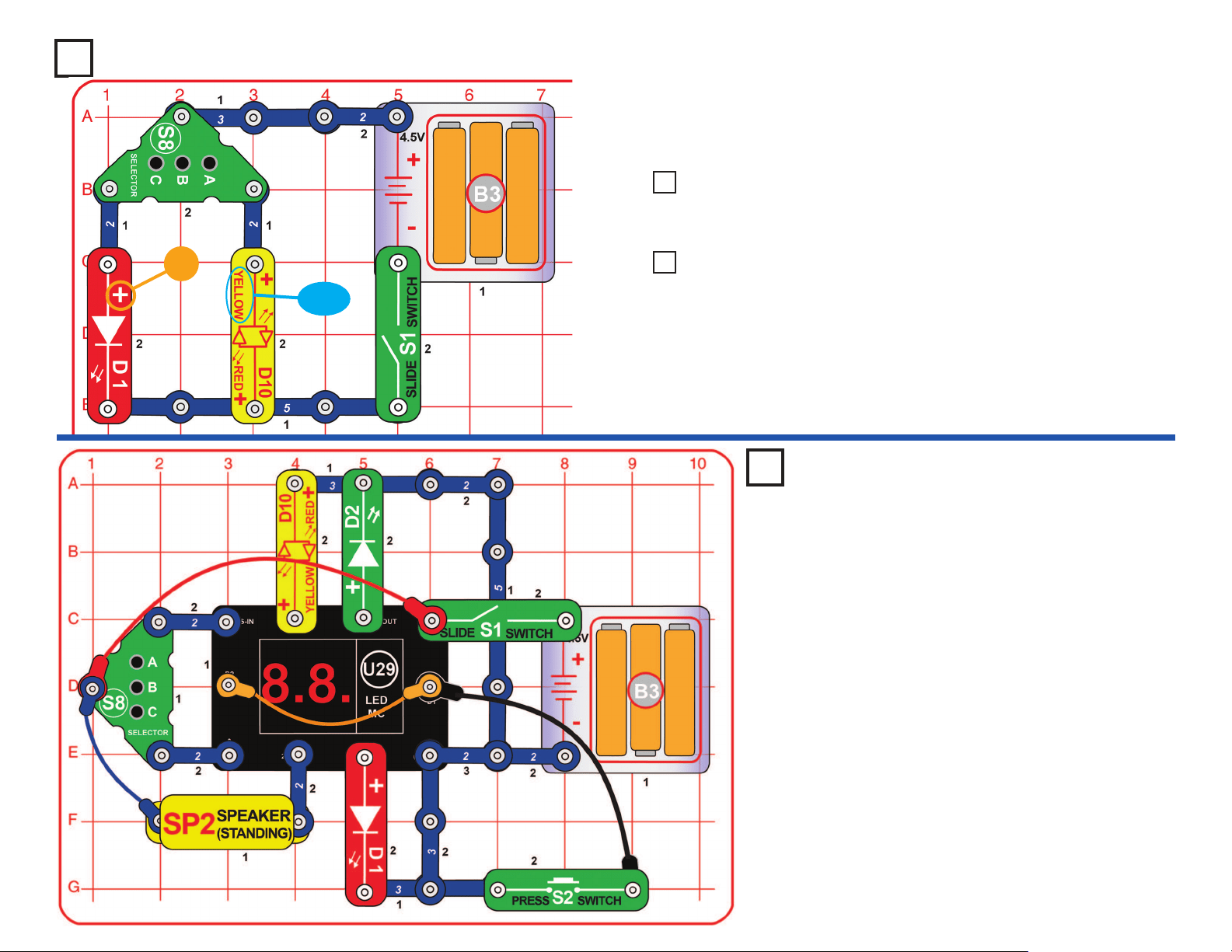
Project 49 Selector
Turn on the slide switch (S1). Press button C on the selector (S8) to
light the red LED (D1), press button A on the selector to light the yellow
LED (D10), or press button B on the selector to light both LEDs.
+
YELLOW
Use the preceding circuit, but reverse the orientation of the yellow bi-
color LED (D10), to make it red.
Project 50 Red Selector
Use the project 49 circuit, but replace either of the LEDs (D1 or
D10) with the green LED (D2).
Project 51 Green Selector
27
Turn on the slide switch (S1); the display on the LED-MC (U29) shows
“00” and a siren sound plays. Press the A button on the selector (S8) once
to make the display show “01”, then press the B button on the selector to
start.
Every few seconds the speaker (SP2) randomly plays one of three siren
sounds, and the U29 LED display shows a random pattern.
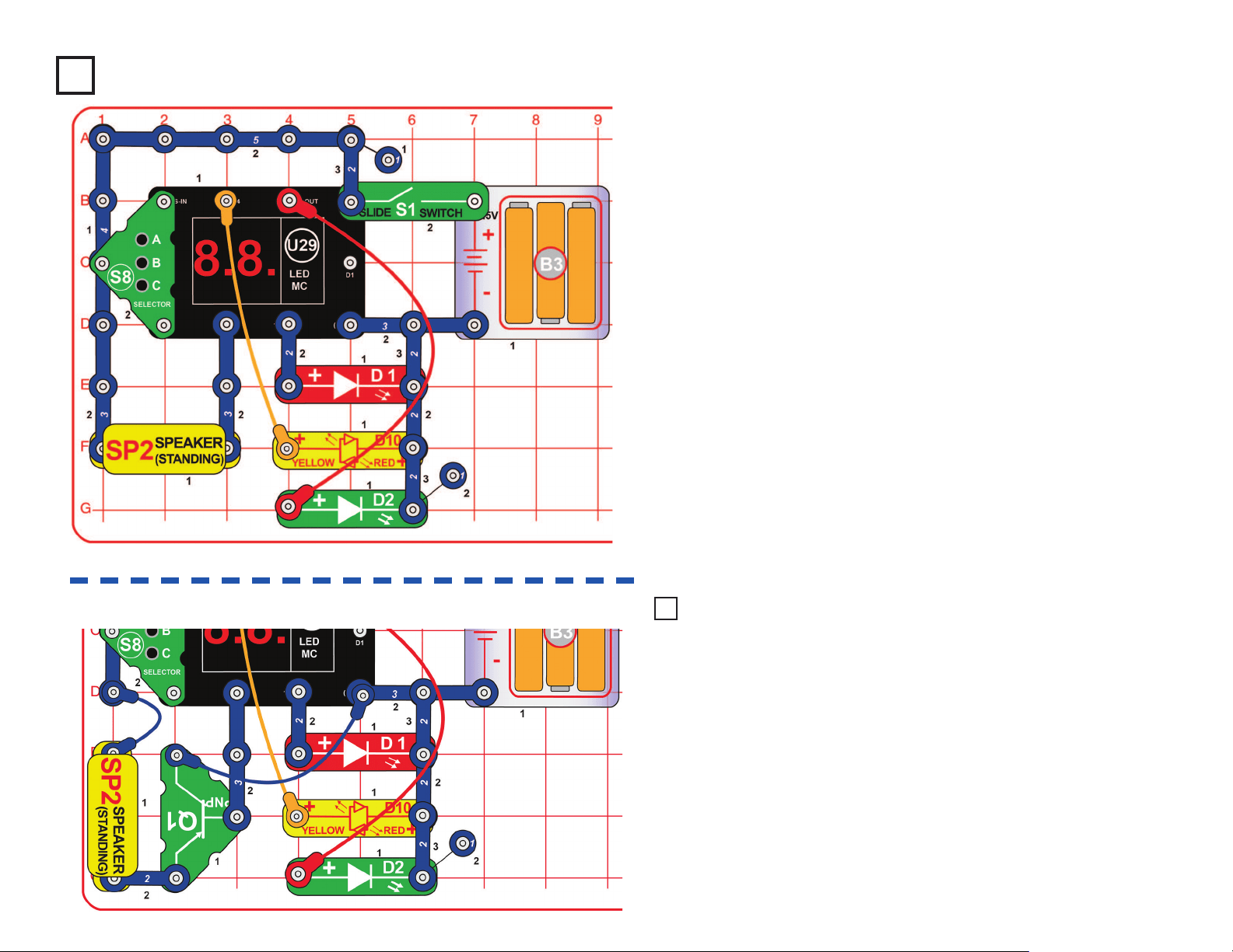
Modify the project 53 circuit by
adding the red & red/yellow LEDs
(D1 & D10) as shown. It works the
same way, but has more lights
and the sound is not as loud.
Modify the preceding circuit
by adding the LEDs in the
disco motor (DM) using blue
& red jumper wires as shown.
It works the same way, but
has more lights.
Project 53
Random Siren Selector
Project 55 Project 56
Use the preceding circuit. Turn on the slide switch (S1); the display on
the LED-MC (U29) shows “00”. Press the A button on the selector (S8)
two or three times to increase the ones digit on the display. When the
display shows “02” or “03”, press the B button on the selector to start.
The circuit works the same, except that it changes faster. “03” is faster
than “02”.
Project 54 Fast Random Siren Selector
LED Random
Siren
Selector
5-LED
Random
Siren
Selector
28
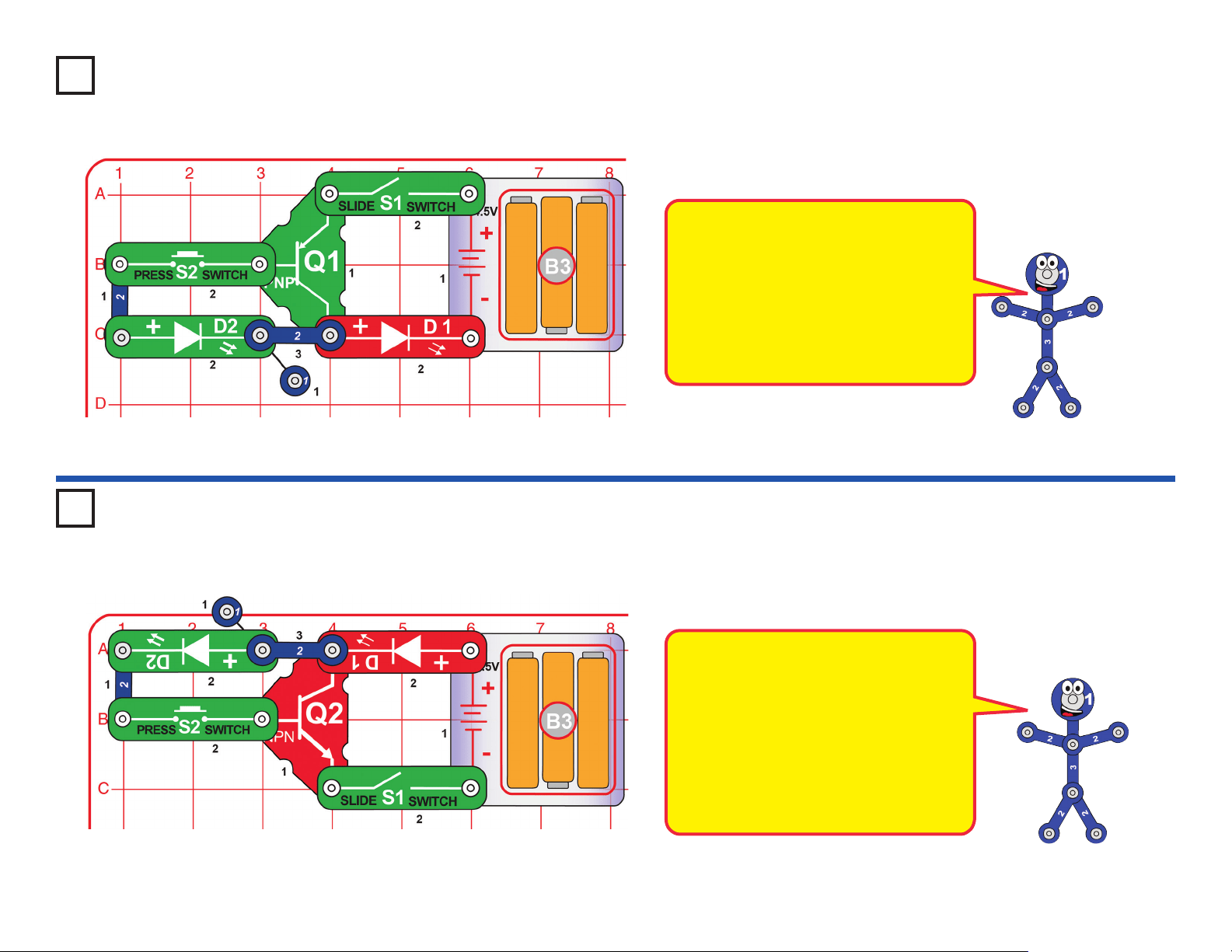
Turn on the slide switch (S1) - nothing happens. Now push the press
switch (S2) and the red LED (D1) lights, but the green LED (D2) stays off.
Turn on the slide switch (S1) - nothing happens. Now push the press
switch (S2) and the red LED (D1) lights but the green LED (D2) stays off.
Project 57
PNP Transistor
Project 58
NPN Transistor
A transistor uses a small electric current
to control a large electric current. Here
pressing S2 makes a small current ow
out of the PNP transistor (Q1) through
the green LED, which triggers a large
current out of the transistor through the
red LED. The green LED is actually
turned on, but is so dim you may not be
able to see it even in a dark room.
The NPN transistor (Q2) is just like the
PNP transistor (Q1) in preceding circuit,
except that the electric currents ow in
the opposite direction. Here pressing
S2 makes a small current ow into the
transistor through the green LED, which
triggers a large current into the transistor
through the red LED. The green LED is
actually turned on, but is so dim you may
not be able to see it even in a dark room.
29
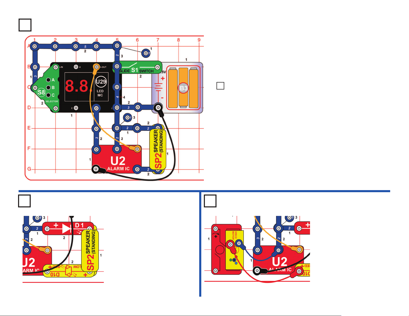
Turn on the slide switch (S1) to hear an alarm.
Variants:
1. Connect a blue jumper wire between points A & B.
2. Move the blue jumper wire to points E & F.
3. Move the blue jumper wire to points B & G.
4. Remove the blue jumper wire. Remove the 3-snap wire between
points C & D, and connect it between points A & B.
Build the circuit as shown, place one of the disco covers on the disco
motor (DM), and turn on the slide switch (S1). Nothing happens. Push &
release the press switch (S2); the green LED (D2) ashes once, turning on
PNP & NPN transistors (Q1 and Q2), so now the disco motor and the LEDs
on it turn on. The circuit will continue to run until switch S1 is turned off.
Transistors Q1 and Q2 act
as a thyristor bistable switch,
conducting electricity when
their gate (the left side of Q2)
is triggered (by pressing S2),
and continuing to conduct until
the circuit is turned off.
Project 60
Thyristor Start Disco Ball
Disco Cover
SUPPORT BAR
Project 59
Sirens
30
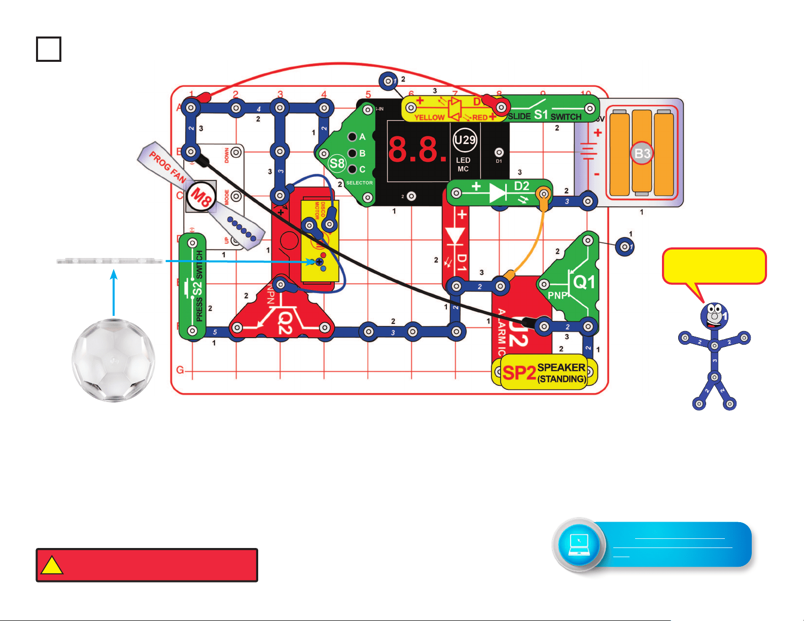
Build the circuit as shown; note that the 5-snap wire is partialy covered by
the NPN transistor (Q2), and a 3-snap wire is partially covered by the green
LED (D2). Place one of the disco covers on the disco motor (DM).
Turn on the slide switch (S1). A siren sounds, the disco motor spins & lights,
and the display on the LED-MC (U29) displays “00”. Push and hold down the
press switch (S2) to spin the programmable fan (M8); if you hold it down long
enough then it cycles through 6 messages.
Make the display on the LED-MC show “02” or “03” by pressing the A button
on the selector (S8) to increase the ones digit on the display. Press the B
button on the selector. The LEDs (D1, D2, & D10) will ash while the display
on U29 displays a random pattern; sometimes they will be rapidly changing,
and sometimes they will stop for a few seconds.
Project 61
Finale
Disco Cover
SUPPORT BAR
This circuit uses all
the parts in your set.
!
WARNING: Moving parts. Do not touch the fan or
motor during operation. Do not lean over the motor.
Go to https://shop.elenco.com/
consumers/snap-circuits-arcade.
html to download projects 62-203
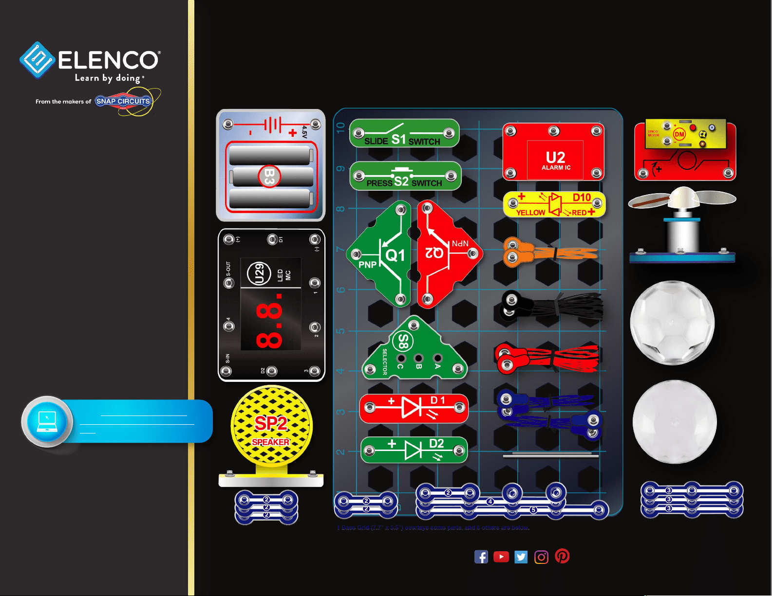
Base Grid (11” x 7.7”) overlays some parts.
SCA-200 Snap Circuits
®
Arcade Parts Layout
Snap Circuits
®
, CircuitSafe
®
, Elenco
®
,
Learn By Doing
®
, and Making Coding
a Snap
®
are registered trademarks
of Elenco Electronics, Inc. All rights
reserved. U.S. Patents: 7,144,255;
7,273,377, & patents pending
Important: If any parts
are missing or damaged,
DO NOT RETURN TO
RETAILER. Call toll-free at:
(800) 533-2441 or e-mail us
at: [email protected].
Customer Service:
150 Carpenter Ave.
Wheeling, IL 60090 U.S.A.
Note: A complete parts list is
on pages 2 in this manual.
www.elenco.com
Not responsible for typographical errors. Colors, styles and case quantities are subject to change without notice.
Go to https://shop.elenco.com/
consumers/snap-circuits-arcade.
html to download projects 62-203