Loading ...
Loading ...
Loading ...
30
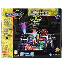
Project 42
Brightness Control
Build the circuit and turn on the slide switch (S1). Move the lever on the
adjustable resistor (RV) to vary the brightness of the light from the white
LED (D6). If desired, you may place any of the LED attachments (tower,
egg, or ber optic tree) on the LED.
Resistors are used to control or limit the ow of electricity in a circuit.
Higher resistor values reduce the ow of electricity in a circuit.
In this circuit, the adjustable resistor is used to adjust the
LED brightness, to limit the current so the batteries last longer, and
to protect the LED from being damaged by the batteries.
What is Resistance? Take your hands and rub them together very
fast. Your hands should feel warm. The friction between your hands
converts your effort into heat. Resistance is the electrical friction
between an electric current and the material it is owing through.
The adjustable resistor can be set for as low as 200W, or as high as
50,000W (50kW).
The R1 resistor (100W) will have little
effect, since it will be dominated by the
adjustable resistor. Resistor R5 (100kW)
is a high resistance, which greatly
restricts the ow of electricity, so the
LED will be very dim or off. Resistor R3
(5.1kW) will be in between those.
Use the preceding circuit, but replace the 3-snap with one of the yellow
resistors in this set (R1, R3, or R5). Observe how each changes the
LED brightness at different settings for the adjustable resistor.
Use the two preceding circuits, but replace the white LED (D6) with the
red LED (D1) or color LED (D8). Vary the adjustable resistor lever and
change the yellow resistors to see how the light varies with each LED.
Project 43 Resistors
Project 44 Resistors & LEDs
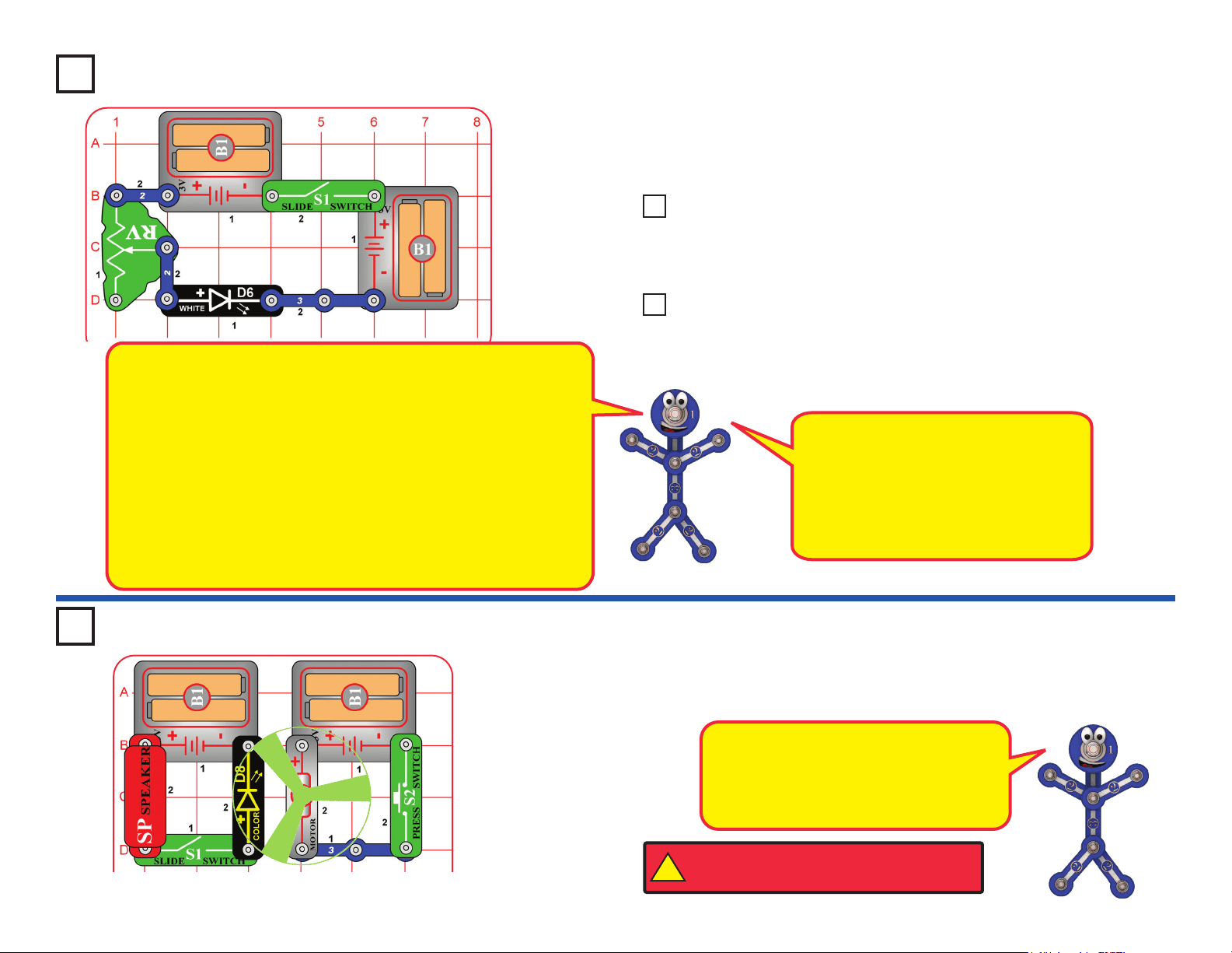
Light Up the FanProject 45
Build the circuit as shown, place the glow fan on the motor (M1), and turn
on the slide switch (S1). Place the circuit in a dark room and push the press
switch (S2) to spin the fan. The color LED (D8) lights up the spinning fan.
The circuit with the color LED is not
electrically connected to the circuit with the
motor. This was done because the motor
produces electrical pulses as it spins, and
these pulses can confuse the color LED.
!
WARNING: Moving parts. Do not touch the fan or
motor during operation. Do not lean over the motor.
Loading ...
Loading ...
Loading ...