Loading ...
Loading ...
Loading ...
36
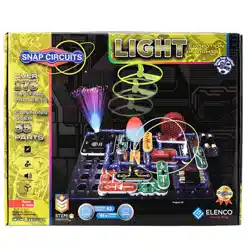
Project 67
This circuit is an
oscillator, which
uses feedback to
control the pitch of
the sound.
Build the circuit as shown and turn on the switch (S1). Move the lever on
the adjustable resistor (RV) to vary the pitch of the buzzing sound.
Use the preceding circuit, but place the 5.1kW resistor directly over the
100kW resistor using a 1-snap. The pitch of the tone is higher now,
but the circuit may not make noise on all settings for the adjustable
resistor.
Project 68 Higher Pitch Buzzer
Use the circuits from projects 67-68, but add the phototransistor (Q4)
across base grid locations B2-B4 (between RV and R1, “+” on the left),
on level 3. Vary the amount of light on the phototransistor to change
the sound, while also varying RV.
Project 69 Photo Light & Motion
Use the circuits from projects 67-68, but replace the 0.1mF capacitor
(C2) with the 100mF capacitor (C4), “+” to the right. Turn the switch on
and patiently wait. The speaker will beep and the color LED (D8) will
ash every 5-20 seconds, depending on the resistors.
Project 70 Slow Light & Motion
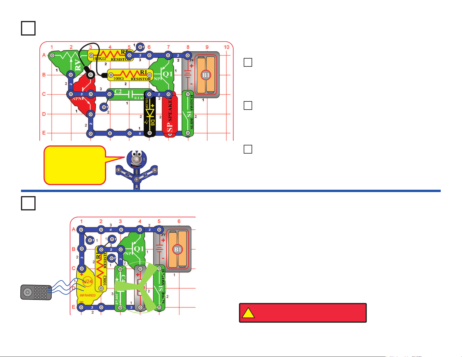
You need an infrared remote control for this project, such as any TV/stereo/
DVD remote control in your home.
Build the circuit and turn on the switch (S1). Point your remote control toward
the infrared module (U24) and press any button to spin the motor (M1).
Next, remove the 100mF capacitor (C4). The circuit works the same, except
now the motor moves in small steps.
Sometimes this circuit may activate without a remote control, due to infrared
in sunlight or some room lights. If this happens, try moving to a darker room.
Project 71
R/C Motor
Remote
Buzzer
!
WARNING: Moving parts. Do not touch the fan or
motor during operation. Do not lean over the motor.
Loading ...
Loading ...
Loading ...