Loading ...
Loading ...
Loading ...
29
Project 40
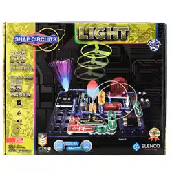
LEDs Together
Project 41
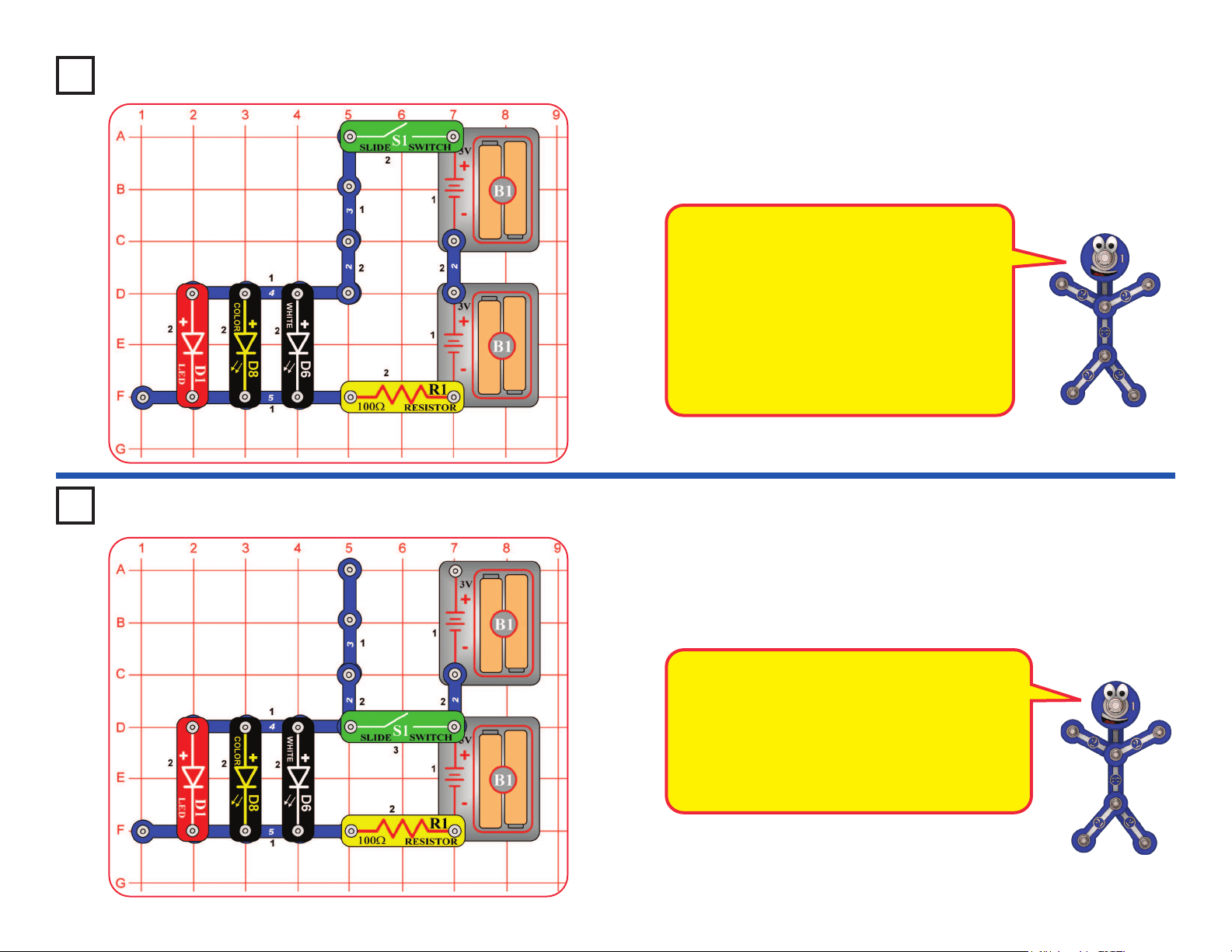
LEDs Together (II)
Turn on the slide switch (S1), and compare the brightness of the three LEDs.
Next, remove any of the LEDs and see how the brightness of the others changes.
Modify the preceding circuit by moving the slide switch (S1) to the location shown
here. Compare the brightness of the LEDs. Some LEDs may not turn on.
Next, remove any of the LEDs and see how the brightness of the others changes.
This circuit reduces the voltage to the circuit,
because only one set of batteries is connected.
The limited battery voltage is split between the
R1 resistor and the LEDs. The remaining voltage
across the LEDs is enough to activate the red
LEDs, but may not be enough to activate the other
colors. With the reduced voltage, the red LED will
dominate even more than in the preceding circuit.
The voltage needed for an LED to turn on
depends on the light color. Red light needs the
least, green needs more, but blue and white
need the most. The color LED (D8) contains
red, green, and blue LEDs.
The R1 resistor reduces the voltage available to
the LEDs. The LED brightness varies because
some of the LEDs need more voltage than is
available. The red LED (D1) will dominate the
other colors because it turns on more easily.
Loading ...
Loading ...
Loading ...