Loading ...
Loading ...
Loading ...
SEQUENCE OF OPERATION
PAGE 21
ENGLISH
Outdoor Temperature Sensors
Five temperature sensors located in the outdoor unit provide
temperature information to the outdoor unit main board for
control of the system during cool mode.
The outdoor ambient temperature sensor provides the tem-
perature of the air drawn into the condenser coil.
The defrost temperature sensor A provides the temperature
sensed at the output of the condenser coil.
The defrost temperature sensor B provides the temperature
sensed at the middle of the condenser coil.
The suction line temperature sensor provides the tempera-
ture sensed at the incoming suction line pipe.
The compressor discharge sensor provides the temperature
sensed at the discharge pipe of the compressor.
Call to Terminate Cooling
The system will terminate cooling when the indoor ambient
temperature sensor is equal to or lower than 2°F of the room
set temperature. The indoor control board will communicate
to the outdoor control board to de-energize the compressor.
The outdoor fan will run for 60 seconds before stopping.
The indoor fan motor and louver will continue operating after
cooling has been terminated.
To stop cool mode, press the power button to turn the system
o, or change to another mode.
Freeze Protection Function
When the compressor operates continuously for 10 seconds
and the temperature of the indoor coil has been below 32°F
for 10 seconds, the compressor will stop. The indoor unit fan
will continue to operate. When the temperature of the indoor
coil rises to 45°F for more than 3 minutes the compressor will
restart and the system will continue functioning.
Heat Mode
Overview
The temperature control range in heating mode is 60°F - 86°F.
The temperature set by the remote control and the indoor
unit ambient temperature sensor will determine if a call for
heat is needed. If a call for heat is justied, a temperature
compensation adjustment is automatically added to the oper-
ating parameter and the call is communicated from the indoor
unit to the outdoor unit.
The indoor unit louver will open using a stepper motor. The
indoor fan will not operate at this time.
The outdoor unit will shift the 4-way valve to the heat mode
position and determine the position of the EEV and speed
(frequency) of the compressor. There can be a delay of up to 3
minutes before the outdoor unit fan and compressor start.
(Tr = room temperature Ts = set temperature)
If Tr ≤ Ts, the outdoor unit will operate and the indoor fan oper-
ates in cold air prevention function
If Tr > Ts, the outdoor unit turns o and the indoor fan oper-
ates at heat residue sending mode.
If Tr < Ts, the outdoor unit will restart and the indoor fan oper-
ates in cold air proof mode.
The speed of the indoor fan can be controlled manually by
the user or automatically by the system. The speed can be
changed between HIGH, MEDIUM, and LOW. The predeter-
mined conditions for automatic control are as follows:
High Speed: Tr < Ts
Medium Speed: Ts ≤ Tr ≤ Ts + 4°F
Low Speed: Tr > Ts + 4°F
When the indoor fan is running in automatic mode when the
speed switches from high to low, the indoor fan will maintain
high speed for a period of 3 minutes before switching to low
speed.
Cold Air Proof Operation
At initial start of heat mode, indoor blower will not be turned
on immediately until indoor coil temperature senses a mini-
mum temperature. This period usually takes 30 seconds to 3
minutes depending on the outdoor ambient temperature.
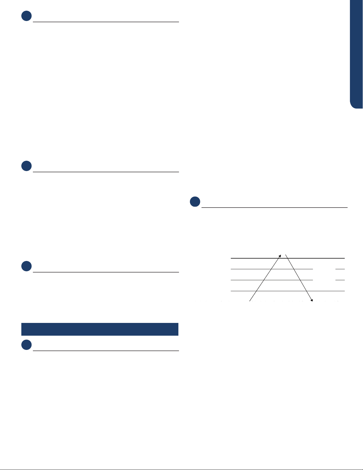
ć
ć
2. 4 minutes after the start up of the indoor fan, the light airflow and the low airflow wi
Heat start temp 1
Heat start temp
2
Heat start temp
3
Heat start temp
4
Set speed
Low speed
Light speed
Fan/off
Fan/off
Keep the hig
h
speed. The fa
n
doesn’t stop
4 minutes after the indoor fan starts, the light or low speed will
switch to the set speed.
Residual heat sending: the indoor fan will operate on low
speed until coil temperature reaches 73°F.
The outdoor unit temperature sensors, including outdoor am-
bient, defrost, suction line, and compressor discharge, used
in conjunction with the indoor coil and room temperature
sensors, provide information to the outdoor control board to
monitor the system and regulate the speed of the compres-
sor, the EEV, and outdoor fan speed to achieve the desired
room temperature.
When heating has been satised, the outdoor unit compres-
sor will turn o rst and followed by the outdoor fan. The
4-way valve will de-energize 2 minutes after compressor
stops.
Loading ...
Loading ...
Loading ...