Loading ...
Loading ...
Loading ...
24
b) Line Set Greater Than 66' (20 m) Up to a Minimum of 100' (30.5 m)
1) Route the factory line set or appropriate size copper tubing. When eld fabricating,
insulate the copper tubes separately. Leave a service loop behind the icemaker to allow
the icemaker to be pulled out for service. See Fig. 7.
Note: • The service loop is not considered an oil trap.
• The maximum line length for the standard line sizes and refrigerant charge is 66' (20
m). With larger line sizes and/or additional refrigerant, the maximum line length is 100'
(30.5 m). For details, see "II.G.4 Line Set Size and Refrigerant Charge."
2) Remove any extra line set length, then insulate the two copper tubes separately.
3) Remove the Schrader valves from the icemaker service valves. Next, place the liquid
line copper tube into the liquid line service valve. Note: The straight copper tube in the
icemaker accessory bag is not used for line sets over 66' (20 m).
NOTICE
• Before brazing, remove the Schrader valve cores from the service valve access
ports.
• When brazing protect the service valve by using a wet cloth to prevent the service
valve from overheating.
• Braze all ttings while purging with a nitrogen gas owing at a pressure of 3 to 4
PSIG.
4) Braze the liquid line copper tube to the icemaker liquid line service valve.
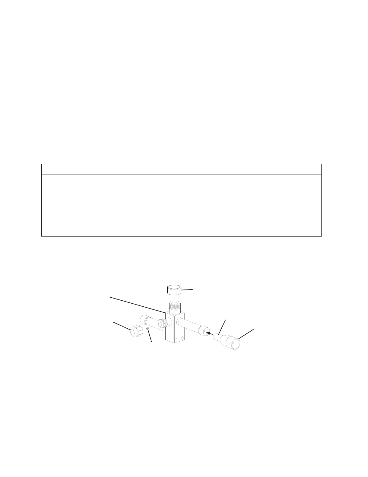
5) Place the 3/8" end of a 1/2"×3/8" copper slip reducer (not provided) in the icemaker
discharge line service valve, then place the discharge line copper tube into the 1/2" end
of the 1/2"×3/8" copper slip reducer. See Fig. 11.
6) Braze the icemaker discharge line copper tube to the 1/2"×3/8" copper slip reducer and
the 1/2"×3/8" copper slip reducer to the icemaker discharge line service valve.
7) Remove the Schrader valves from the condenser unit service valves. Next, place the
liquid line copper tube into the liquid line service valve. Note: The straight copper tube in
the condenser unit accessory bag is not used for line sets over 66' (20 m).
8) Braze the liquid line copper tube to the condenser unit liquid line service valve.
9) Place the 3/8" end of a 1/2"×3/8" copper slip reducer (not provided) in the condenser
unit discharge line service valve, then place the discharge line copper tube into the 1/2"
end of the 1/2"×3/8" copper slip reducer. See Fig. 11.
Service Valve CapCondenser Unit Discharge Line
Service Valve
Access Valve Cap
Shrader Valve
1/2×3/8 Copper Reducer
1/2" Diameter End
Fig. 11
Loading ...
Loading ...
Loading ...