Loading ...
Loading ...
Loading ...
Some obstacles are resistant to a collision, for example,
trees or bushes that are more than 15 cm / 5.9 in. in
height. The product will collide with the obstacle and
then select a new direction.
• Put the boundary wire to and around the obstacle
to make an island.
• Put the 2 sections of boundary wire to and from the
island close together. This will make the product
run across the wire.
• Put the 2 sections of boundary wire in the same
stake.
0 cm / 0
"
3.4.3.4 To make a secondary area
Make a secondary area (B) if the work area has 2 areas
that are not connected with a passage. The work area
with the charging station is the main area (A).
Note:
The product must be manually moved between
the main area and the secondary area.
B
A
• Put the boundary wire around the secondary area
(B) to make an island. Refer to
To make an island
on page 15
.
Note:
The boundary wire must be put as 1 loop
around all of the work area (A + B).
Note: When the product cuts grass in the
secondary area, the
Secondary area
mode must
be selected. Refer to
Operating modes on page
26
.
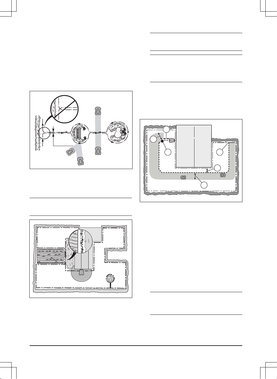
3.4.4 To examine where to put the guide
wire
Put the guide wire from the charging station through the
work area and connect it to the boundary wire. The
installation of the guide wire is important for a successful
guide calibration, refer to
Guide calibration on page 20
.
F
D
C E
A
B
• Put the guide wire in a line at a minimum of 1 m /
3.3 ft. in front of the charging station (A).
• Put the guide wire minimum 30 cm / 1 ft. from the
boundary wire (B).
• Starting point (C). Refer to
Starting point on page
24
.
• Minimum distance 60 cm / 2 ft. perpendicular to the
guide wire (D). If less distance, the calibration
process is interrupted. For the widest possible
guide corridor, have a minimum distance of 1.35
m / 4.5 ft. Refer to
Guide calibration on page 20
.
• Where the guide wire is connected to the boundary
wire (E).
• Guide corridor (F). The product always runs to the
left of the guide wire as seen facing the charging
station. Make sure that the guide wire has as much
free area as possible to the left of the guide wire.
Note:
The product always runs in the guide
corridor but changes the distance to the guide
wire.
16 - Installation 1411 - 007 - 23.09.2020
Loading ...
Loading ...
Loading ...