Loading ...
Loading ...
Loading ...
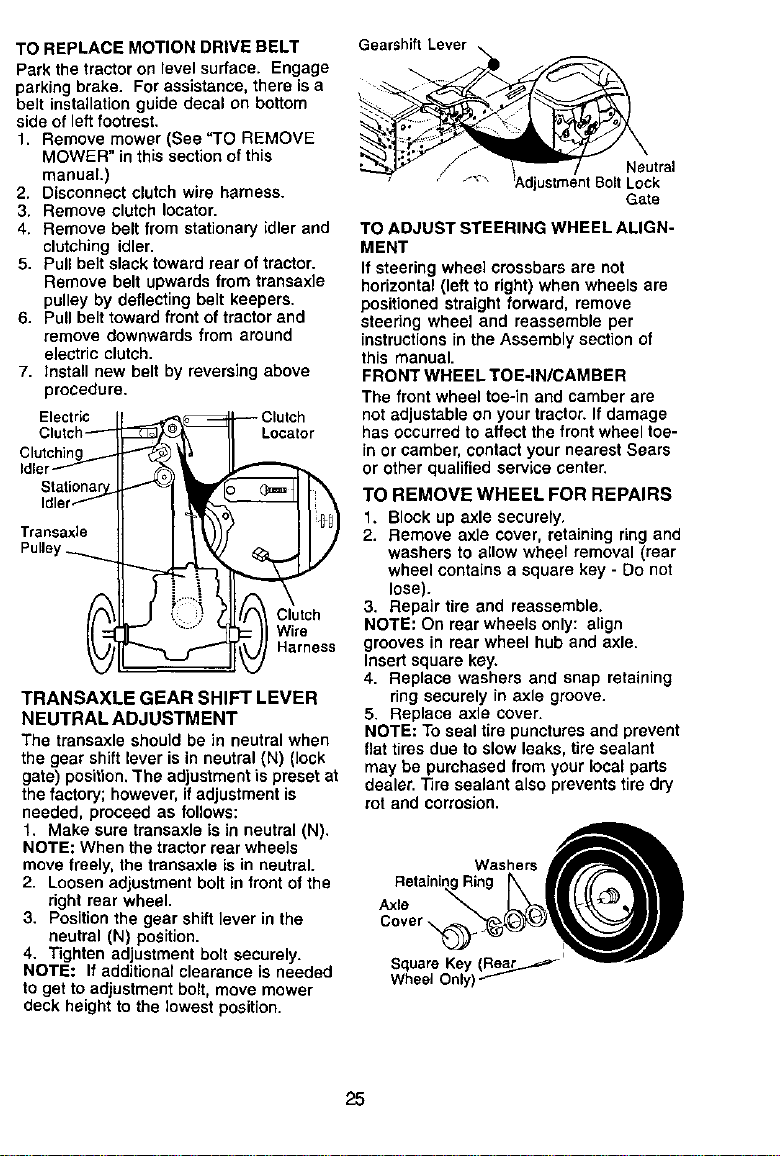
TO REPLACE MOTION DRIVE BELT
Park the tractoron levelsurface. Engage
parkingbrake. For assistance,there isa
belt installationguide decal on bottom
side of leftfootrest.
1. Remove mower (See "TO REMOVE
MOWER" inthis sectionof this
manual.)
2. Disconnect clutch wire harness.
3. Remove clutch Iocator.
4. Remove belt from stationary idler and
clutching idler.
5. Pull belt slack toward rear of tractor.
Remove belt upwards from transaxle
pulley by deflecting belt keepers.
6. Pull belt toward front of tractor and
remove downwards from around
electric clutch.
7. Install new belt by reversing above
procedure.
Electric
Clutch_
Clutching
Idler_
Stati_.
Idler
Transaxle
Pulley ._.......
_ _ Clutchr
_ Harness
TRANSAXLE GEAR SHIFT LEVER
NEUTRAL ADJUSTMENT
The transaxle should be in neutralwhen
the gear shiftlever is in neutral(N) (lock
gate) position. The adjustment is preset at
the factory; however, if adjustment is
needed, proceed as follows:
1. Make sure transaxle is in neutral (N).
NOTE: When the tractorrear wheels
move freely, the transaxle isin neutral.
2. Loosen adjustment boltin front ofthe
right rear wheel.
3. Positionthe gear shift lever in the
neutral (N) position.
4. Tighten adjustmentbctt securely.
NOTE: If additionalclearance is needed
toget to adjustmentbolt, move mower
deck heightto the lowest position.
Gearshift Lever
Gate
TO ADJUST STEERING WHEEL ALIGN-
MENT
If steering wheel crossbars are not
horizontal(left to right)when wheels are
positioned straight fon_ard, remove
steering wheel and reassemble per
instructions in the Assembly sectionof
this manual.
FRONT WHEEL TOE-IN/CAMBER
The front wheel toe-in and camber are
notadjustable on your tractor.If damage
has occurred toaffect the front wheel toe-
in or camber,contactyour nearestSears
or other qualifiedservice center.
TO REMOVE WHEEL FOR REPAIRS
1. Block up axle securely,
2. Remove axle cover, retaining ring and
washers to allow wheel removal (rear
wheel contains a square key - Do not
lose).
3. Repair tire and reassemble.
NOTE: On rear wheels only: align
grooves in rear wheel huband axle.
Insert square key.
4. Replace washers and snap retaining
ring securely in axle groove.
5. Replace axle cover.
NOTE: To seal tire puncturesand prevent
flat tires due toslow leaks, tire sealant
may be purchased from your local parts
dealer.Tire sealant also prevents tire dry
rot and corrosion.
Washers "__
RetainingRing kII//F_lll
Cover
SquareKey(ReajL..._=_ -,_,-_w--
Wheel Only)
25
Loading ...
Loading ...
Loading ...