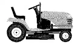

Owner's Manual
2O HP
ELECTRIC START
48" MOWER
6 SPEED TRANSAXLE
LAWN TRACTOR
Model No.
917.272234
• Safety
• Assembly
• Operation
• Maintenance
• Repair Parts
CAUTION:
Read and follow all
Safety Rules and Instructions
before operating this equip-
ment.
For answers to your questions
about this product, Call:
1-800-659-5917
Sears Craftsman Help Line
5 am- 5 pro, Mon - Sat
Sears, Roebuck and Co., Hoffman Estates, IL 60179
Visit our Craftsman website: www.sears.com/craftsman
Warranty ............................................... 2
Safety Rules ......................................... 3
Product Specifications .......................... 6
Assembly .............................................. 8
Operation ............................................ 12
Maintenance Schedule ...................... 18
Maintenance ....................................... 18
Service and Adjustments .................... 22
Storage ............................................... 29
Troubleshooting ................................. 30
Repair Parts ........................................ 34
Parts Ordering ..................... Back Cover
LIMITED TWO YEAR WARRANTY ON CRAFTSMAN RIDING EQUIPMENT PARTS
For two (2) years from the date of purchase, if this Craftsman Riding Equipment is
maintained, lubricated and tuned up according to the instructions in the owner's
manual, Sears will repair or replace, free of charge, any parts found to be defective in
material or workmanship. Warranty service is available free of charge by returning your
Craftsman ridingequipment to your nearest Sears Service Center. In-home warranty
service is available but a trip charge will apply. This warranty applies only while this
product is in the United States.
This Warranty does not cover:
• Expendable items which become worn during normal use, such as blades, spark
plugs, air cleaners, belts and oil filters.
• Tire replacement or repair caused by punctures from outside objects, such as nails,
thorns, stumps, or glass.
• Repairs necessary because of operator abuse, including but not limited to, damage
caused by towing objects beyond the capability of the riding equipment, impacting
objects that bend the frame or crankshaft, or over speeding the engine.
• Repairs necessary because of operator negligence, includingbut not limited to,
electrical and mechanical damage caused by improper storage, failure to use the
proper grade and amount of engine oil, failure to keep the deck clear of flammable
debris, or the failure to maintain the equipment according to the instructions con-
tained in the owner's manual.
• Engine (fuel system) cleaning or repairs caused by fuel determined to be contami-
nated or oxidized (stale). In general, fuel should be used within thirty (30) days of its
purchase date.
• Riding equipment used for commercial or rental purposes. A product is "used for
commercial purpose" if is used for any purpose other than single family household
dwellings or in usage where profit is made.
LIMITED 99 DAY WARRANTY ON BA'I-FERY
For ninety (90) days from date of purchase, if any battery included with this riding
equipment proves defective in material or workmanship and our testing determines the
battery will not hold a charge, Sears will replace the battery at no charge. Warranty
service is available free of charge by returning your Craftsman riding equipment to
your nearest Sears Service Center. In-home warranty service is available but a trip
charge will apply. This warranty applies only while this product is in the United States.
TO LOCATE THE NEAREST SEARS SERVICE CENTER OR TO SCHEDULE IN-HOME
WARRANTY SERVICE, SIMPLY CONTACT SEARS AT 1-8O0-4-MY-HOME
This Warranty gives you specific legal rights, and you may also have other rights which
may vary from state to state.
Sears, Roebuck and Co,, D/817 WA, Hoffman Estates, IL 60179
2
MPORTANT: This cuttingmachine iscapable of amputating hands and feet and
throwingobjects. Failure to observe the following safety instructionscould resultin
seriousinjuryor death.
I. GENERAL OPERATION
• Read, understand, end follow all
instructionsin the manual end on the
machine before starting.
• Only allow responsibleadults, who are
familiarwith the instructions, to operate
the machine.
• Clear the area of ob ects suchas
recks, toys, w re, etc,, wh ch cou d be
picked up and thrown by the blade.
• Be sure the area is clear of other
people before mowing. Stop machine
if anyone enters the area.
• Never carry passengers.
• Do not mow m reverse unless abso-
lutely necessary. Always look down
and behind betore and while backing.
• Be aware of the mower discharge
direction and do not point it at anyone.
Do not operate the mower without
either the entire grass catcher or the
guard in place.
• Slow down before turning.
• Never leave a running machine
unattended. Always turn off blades, set
parking brake, stop engine, and
remove keys before dismounting.
• Turn off blades when not mowing.
• Stop engine before removing grass
catcher or uncloggingchute.
• Mow only in daylight or good artificial
light.
• Do not operate the machine while
under the influence of alcohol or drugs.
• Watch for traffic when operating near or
crossing roadways.
• Use extra care when loading or
unloading the machine into a trailer or
truck.
• Data indicates that operators, age 60
years and above, are involved in a
large percentage of dding mower-
related injuries. These operators
should evaluate their ability to operate
the riding mower safely enough to
protect themselves and others from
serious injury.
• Keep machine free of grass, leaves or
other debris build-up which can touch
hot exhaust / engine parts and burn.
Do not allow the mower deck to plow
leaves or other debris which can cause
build-upto occur. Clean any oil or fuel
spillage before operating or storing the
machine. Allow machine to cool before
storage.
II. SLOPE OPERATION
Slopes are a majorfactorrelated to loss-of-
control and tipover accidents, which can
resultin severe injuryor death. All slopes
requireextra caution. Ifyou cannotback up
the slope or if you feel uneasy on it, do not
mow it.
DO:
• Mow up and down slopes, not across.
• Remove obstacles such as rocks,tree
limbs, etc.
• Watch for holes, ruts,orbumps.
Uneven terrain could overturnthe
machine. Tall grass can hide ob-
stacles.
• Use slow speed. Choose a low gear
SOthat you will not have to stop or shift
while on the slope.
• Follow the manufacturer's recommen-
dations for wheel weights or counter-
weights to improve stability.
• Use extra care with grass catchers or
other attachments. These can change
the stabilityof the machine.
• Keep all movement on the slopes slow
and gradual Do not make sudden
changes in speed or direction.
• Avoid starting or stopping on a slope. If
tires lose traction, disengage the
blades and proceed slowly straight
down the slope.
DO NOT:
• Do not turnon slopes unless neces-
sary, and then, turn slowlyand gradu-
ally downhill, if possible.
• Donotmowneardrop-offs, ditches, or
embankments. The mower could
suddenly turn over if a wheel is over
the edge of a cliffor ditch, or if an edge
caves in.
• Do notmow on wet grass. Reduced
traction couldcause sliding.
• Do not try to stabilize the machine by
putting your foot on the ground.
• Do not use grass catcher on steep
slopes.
Ill. CHILDREN
Tragic accidents can occur ifthe operator
is not alertto the presence of children.
Childrenare oftenattracted to the
machine and the mowing activity, Never
assume that children will remain where
you last saw them.
• Keep children out of the mowing area
and under the watchfulcare ofanother
responsible adult.
• Be alert and turnmachine off if children
enterthe area.
• Before and when backing, look behind
and down for small children.
• Never carry children. They may tal_off
and be seriously injured or interfere
with safe machine operation.
• Never allow children to operate the
machine.
• Use extra care when approaching blind
corners, shrubs, trees, or other objects
that may obscure vision.
IV. SERVICE
• Use extra care in handling gasoline
and other fuels. They are flammable
and vapors are explosive.
-Use only an approved container.
-Never remove gas cap or add fuel
with the engine running. Allow
engine to cool before refueling. Do
notsmoke.
-Never refuel the machine indoors.
-Never store the machine or fuel
container inside where there is an
open flame, such as a water heater.
• Never run a machine inside a closed
area.
• Keep nutsand botts, especially blade
attachmentbolts, tight and keep
equipment in good condition.
• Never tamper with safety devices.
Check their proper operation regularly,
• Keep machinefree of grass, leaves, or
other debris buUd-up, Clean oil or fuel
spillage. Allow machine to cool before
storing.
• Stop and inspectthe equipmentif you
strike an object. Repair, if necessary,
before restarting.
• Never make adjustments or repairs
with the engine running,
• Grass catchercomponentsare subject
to wear, damage, and deterioration,
which could expose moving parts or
allow objectsto be thrown. Frequently
check components and replace with
manufacturer's recommended parts,
when necessary.
• Mower blades are sharp and can cut.
Wrap the blade(s) or wear g_oves, and
use extra cautionwhen servicing them.
• Check brake operation frequently.
Adiast and service as required.
• Be sure the area is clear of other
people before mowing. Stop machine if
anyone enters the area.
• Never carry passengers or children
even with the blades off.
• Do not mow in reverse unlessabso-
lutely necessary. Always look down
and behind before and while backing.
• Never carry children.They may fall off
and be seriously injured or interfere
with safe machine operation.
• Keep children out of the mowing area
and under the watchfulcare of another
responsible adult.
• Be alert and turnmachine off if children
enter the area.
• Before and when backing, look behind
and down for small children.
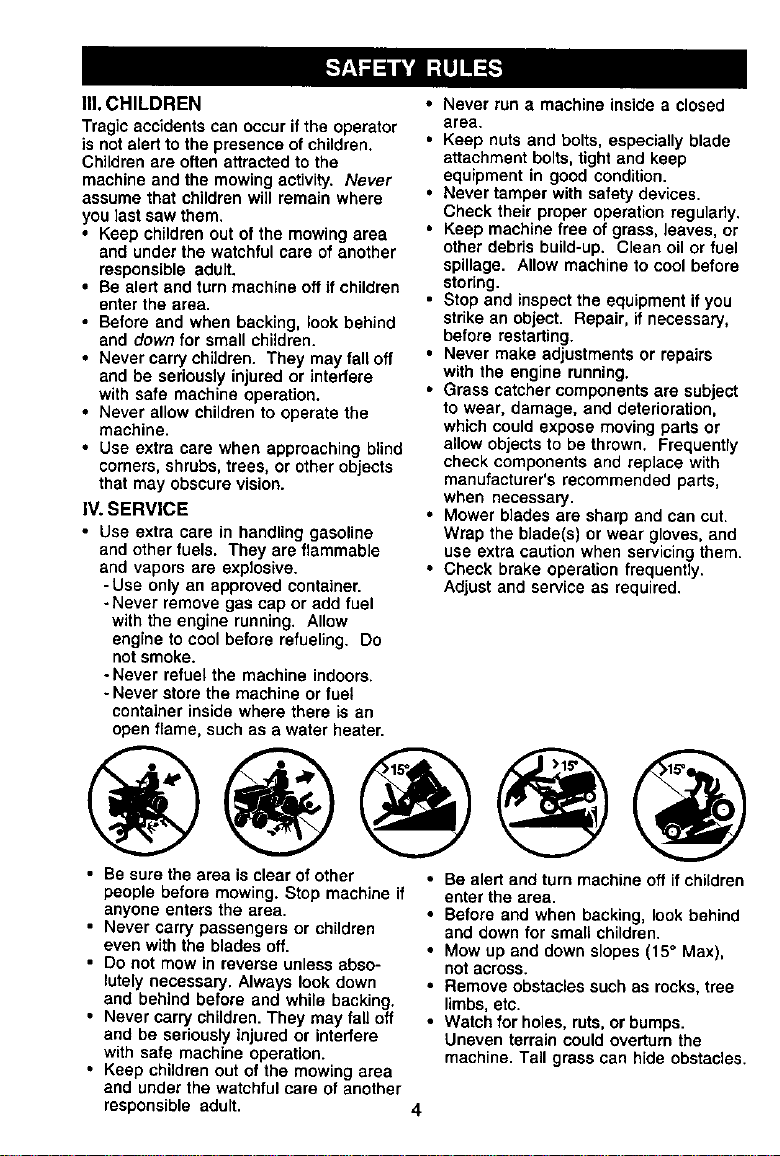
• Mow up and down slopes (15" Max),
not across.
• Remove obstacles such as rocks,tree
limbs,etc.
• Watch for holes, ruts, or bumps.
Uneven terrain couldoverturn the
machine. Tall grass can hide obstacles.
4
• Use slow speed. Choose a low gear so
that you will not have tostop or shift
while on the slope.
• Avoid starting or stoppingon a slope. If
tiros lose traction,disengage the
blades and proceed slowly straight
down the slope.
• If machine stops while going uphill,
disengage blades, shift into reverse
and back down slowly.
• DOnot turn on slopes unlessneces-
sary, and then, turnslowly and gradu-
ally downhill,if possible.
A_Look for thissymbol to point out
importantsafety precautions.It means
CAUTION!H BECOMEALERT!!! YOUR
SAFETY ISINVOLVED.
ACAUTION: In order to preventacciden-
tal startingwhen setting up, transporting,
adjusting or making repairs, always
disconnect spark plug wire and place
wire where it cannotcontact spark plug.
_,CAUTION: Do not coast down a hill in
neutral, you may lose controlof the
tractor.
ACAUTION: Tow onlythe attachments
that are recommended by and comply
with specificationsof the manufacturerof
your tractor. Use common sense when
towing. Operate onlyat the lowest
possiblespeed when on a slope. Too
heavy of a load, while on a slope, is
dangerous. Tires can losetractionwith
the ground and cause you to lose control
ofyour tractor.
_kWARNING: Engineexhaust some of ts
constituents,and certa n veh ce compo-
nents containor emit chemicals known to
the State of California tocause cancer
and birth defects or other reproductive
harm.
,_WARNING: Battery posts terminalsand
related accessories conta nead and lead
compounds,chemicals known to the State
of California to cause cancer and birth
defects or other reproductiveharm. Wash
hands after handling.
5
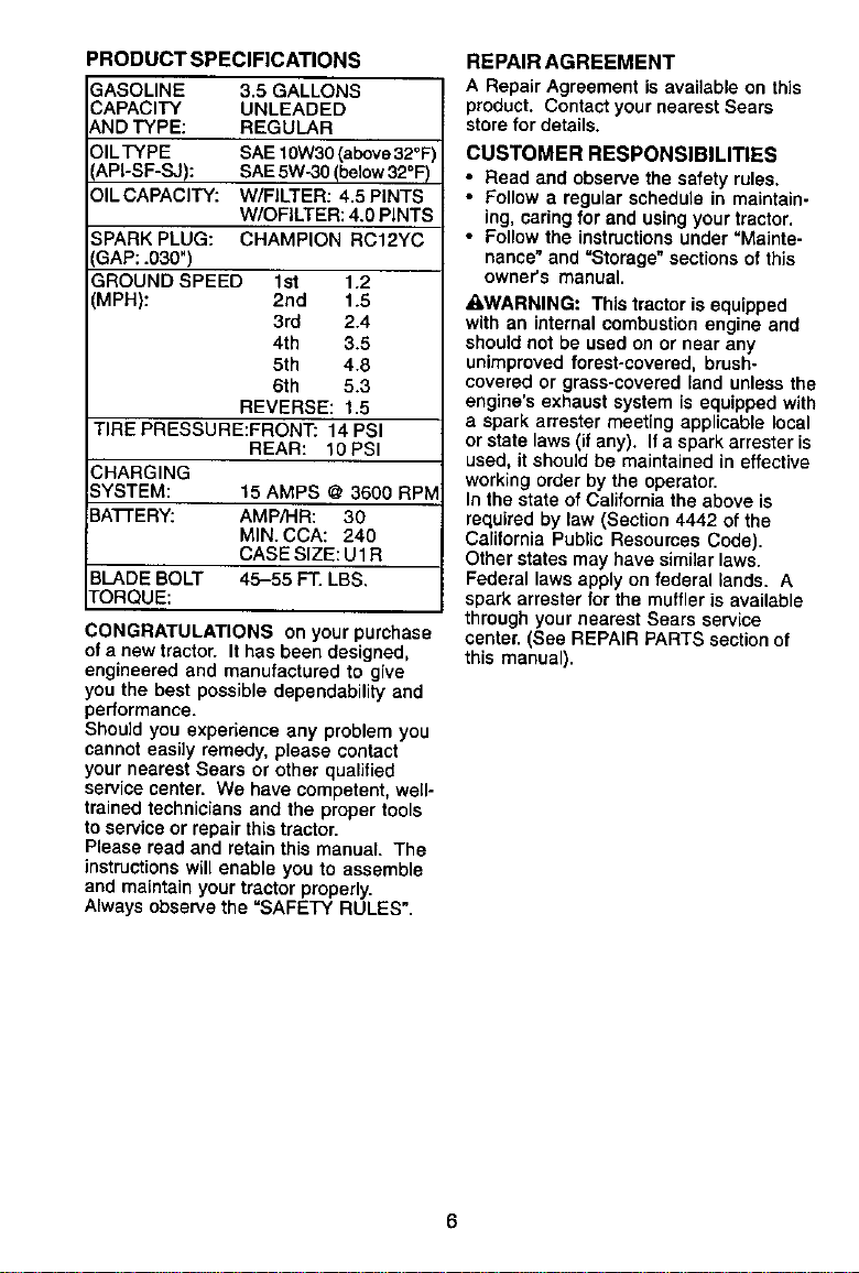
PRODUCT SPECIFICATIONS
ASOLINE 3.5 GALLONS
=,PAClTY UNLEADED
_JDTYPE: REGULAR
ILTYPE SAE 10W30(above32°F)
,PI-SF-SJ): SAE5Wo30(below32°F)
IL CAPACITY: W/FILTER: 4.5 PINTS
W/OFILTER: 4.0 PINTS
;PARKPLUG: CHAMPION RC12YC
GAP: .030")
3ROUND SPEED 1st 1,2
MPH): 2nd 1,5
3rd 2.4
4th 3.5
5th 4.8
6th 5.3
REVERSE: 1.5
"IRE PRESSURE:FRONT: 14 PSI
REAm; _0PSI
;HARGING
YSTEM: 15 AMPS @ 3600 RPIV
ATrERY: AMP/HA: 30
MIN. CCA: 240
CASE SIZE: U1R
BLADE BOLT 45-55 FT. LBS.
['ORQUE:
ONGRATULATIONS on your purchase
o| a new tractor. It has been designed,
engineered and manufactured to give
you the best possible dependability and
performance.
Should you experience any problem you
cannot easily remedy, please contact
your nearest Sears or other qualified
service center. We have competent, well-
trained technicians and the proper tools
to service or repair this tractor.
Please read and retain this manual. The
instructions will enable you to assemble
and maintain your tractor properly.
Always observethe =SAFETY RULES".
REPAIR AGREEMENT
A Repair Agreement is available on this
product. Contactyour nearest Sears
storefor details.
CUSTOMER RESPONS|B|LITIES
• Read and observe the safety rules.
• Fctlow a regular schedule in maintain-
ing, caringfor and using your tractor.
• Follow the instructions under "Mainte-
nance" and =Storage" sections of this
owner's manual.
_,WARNING: This tractor is equipped
with an internalcombustion engine and
should not be used on or near any
unimproved forest-covered, brush-
covered or grass-covered land unlessthe
engine's exhaust system is equipped with
a spark arrester meeting applicable local
or state laws (if any). If aspark arrester is
used, it should be maintained in effective
working order by the operator.
In the state of California the above is
required by law (Section 4442 of the
California Public Resources Code).
Other states may have similar laws,
Federal laws apply on federal lands. A
spark arrester for the muffler is available
through your nearest Sears service
center. (See REPAIR PARTS section of
this manual).
6
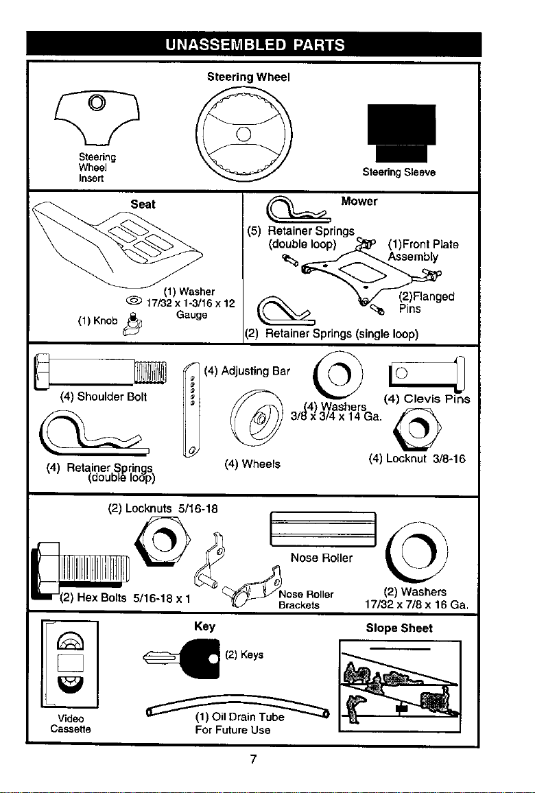
Steering
Wheel
Insert
Steering Wheel
Steering Sleeve
f_. Seat
(1) Washer
17/32 x 1-3/16 x 12
(1) Knob t'_ Gauge
Mower
i(5) Retainer Springs
(double loop) _P (1)Front Plate
',2) Retainer Springs (single loop)
F (4) Adjusting Bar
(4) Shoulder Bolt _
(4) Retainer Springs (4) Wheels
,_double Ioopj
(4) Locknut 3/8-16
(2) Locknuts 5/16-18
_ [
--____ Nose Roller
u- (2) .ex Bolts 5/16-18 x 1 _'-_J Nr°aScekR°s''er
(2) Washers
17/32 x 7/8 x 16 Ga,
< KeI Slope Sheet
(2) Keys
Video
Cassette For Future Use
7
Yournewtractorhasbeenassembled at the factory with exception of those parts left
unassembled for shipping purposes. To ensure safe and proper operation of your
tractor all parts and hardware you assemble must be tightened securely. Use the
correct tools as necessary to insure proper tightness. Review the video cassette before
you begin.
TOOLS REQUIRED FOR ASSEMBLY
A socket wrench set will make assembly
easier. Standard wrench sizes you need
are listed below.
(1) 9/16" Wrench (1) 3/4" Socket w/
(1) 1/2" wrench drive ratchet
(1) Utility knife (1) Pliers
(1) Tire pressure gauge
When dght or left hand is mentioned in
this manual, it means, from your point of
view, when you are in the operating
position (seated behind the steering
wheel).
TO REMOVE TRACTOR FROM
CARTON
UNPACK CARTON
1. Remove all accessible loose parts
and parts boxes from shipping carton.
2. Cut, from top to bottom, along lines on
all four corners of shipping carton, and
lay panels flat.
3. Remove mower and package materi-
als.
4. Check for any additional loose parts
or boxes and remove.
BEFORE REMOVING TRACTOR
FROM SKID
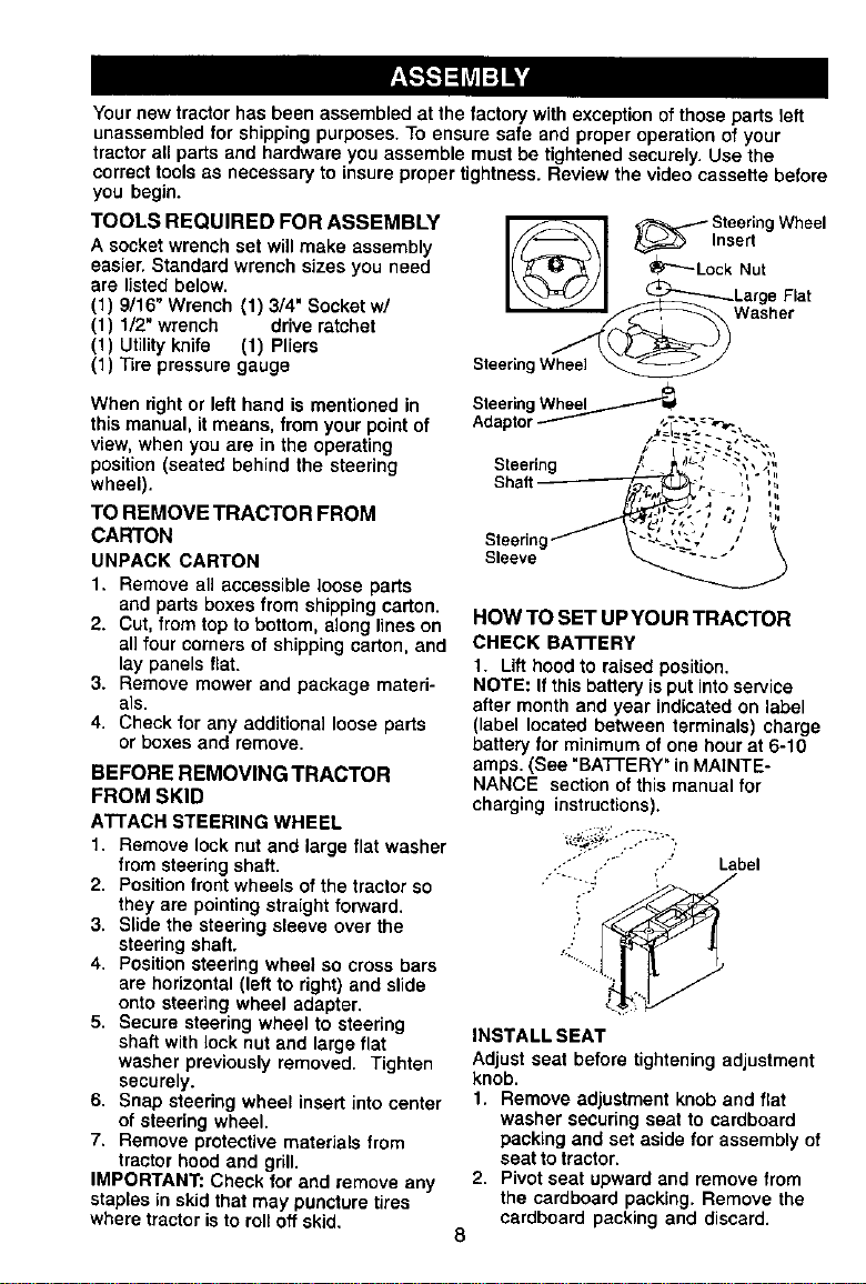
ATTACH STEERING WHEEL
t. Remove lock nutand large flat washer
from steeringshaft.
2. Positionfront whee[s o1the tractor so
they are pointingstraightforward.
3. Slide the steering sleeve over the
steering shaft.
4. Positionsteering wheel so crossbars
are horizontal(left to right)and slide
onto steering wheel adapter.
5. Secure steering wheel to steering
shaft with lock nutand large flat
washer previouslyremoved. Tighten
securely.
6, Snap steering wheel insertinto center
of steering wheel.
7. Remove protective materials from
tractor hood and grill.
IMPORTANT: Check for and remove any
staplesin skid that may puncture tires
where tractor isto roltoff skid,
SteeringWheel
_ _lnsert
SteeringWheel _
Whee, 4
SteeringWheel
Adaptor_ -'" .
Steering
Shaft
Sleeve
HOW TO SET UP YOUR TRACTOR
CHECK BATTERY
t. Lifthood to raisedposition,
NOTE: Ifthis battery is put intoservice
after monthand year indicatedon label
(label located between terminals) charge
battery for minimum ofone hour at 6-10
amps. (See "BATTERY"in MAINTE-
NANCE sectionof this manual for
charging instructions).
.- . ..' Label
INSTALL SEAT
Adjustseat before tighteningadjustment
knob,
1. Remove adjustment knob and flat
washer securingseat to cardboard
packing and set aside for assembly o1
seat to tractor.
2, Pivot seat upward and remove from
the cardboard packing. Remove the
cardboard packing and discard.
8
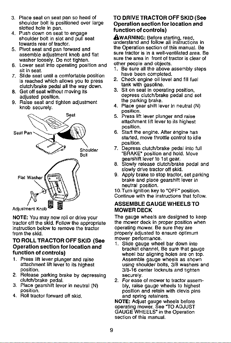
3. Place seat on seat pan so head of
shoulder bolt is positioned over large
slotted hole in pan.
4. Push down on seat to engage
shoulder bolt in slot and pull seat
towards rear of tractor.
5. Pivot seat and pan forward end
assemble adjustment knob and flat
washer loosely. Oo not tighten.
6. Lower seat into operating position and
sit in seat.
7. Slide seat until a comfortable position
is reached which allows you to press
clutch/brake pedal all the way down.
8. Get offseat withoutmoving its
adjusted position.
9. Raise seat and tighten adjustment
knob securely.
Seat
SeatP_
Shoulder
Bolt
NOTE: You may now rollor drive your
tractor off the skid. Followthe appropriate
instruction below to remove the tractor
from the skid.
TO ROLL TRACTOR OFF SKID (See
Operation section for location and
function of controls)
1. Press lift lever plunger and raise
attachmentliftlever to its highest
position.
2. Release parking brake by depressing
clutch/brake pedal.
3. Place gearshift lever in neutral (N)
position.
4. Roll tractorforward offskid.
TO DRIVE TRACTOR OFF SKID (See
Operation section for location and
function of controls)
_WARNING: Before starting,read
understand and follow all instructions in
the Operation section of this manual Be
sure tractor is in a well-ventilated area. Be
sure the area infront oftractorisclearof
other people and objects.
1. Be sure all the above assembly steps
have been completed.
2. Check engine oil level and fill fuel
tank with gasoline.
3. Sit on seat in operating position,
depress dutch/brake pedal and set
the parking brake.
4. Place gear shift lever in neutral (N'I
position.
5. Press lift lever plunger and raise
attachment lift lever to its highest
position.
6. Start the engine. After engine has
started, move throttle control to idle
position.
7. Depress clutch/brake pedal into full
"BRAKE" position and hold. Move
gearshift lever to 1st gear.
8. Slowly release clutch/brake pedal and
slowly drive tractor off skid.
9. Apply brake to stop tractor, set parking
braise and place gearshift lever in
neutral position.
10.Turn ignition key to "OFF" position.
Continue with the instructions that follow.
ASSEMBLE GAUGE WHEELS TO
MOWER DECK
The gauge wheels are designed to keep
the mower deck in proper positionwhen
operating mower. Be sure they are
properly adjusted to ensure optimum
mower performance.
1. Slide gauge wheel bar down into
bracket channel, Be sure that gauge
wheel bar aligningholes are on top.
Assemble gauge wheels as shown
using shoulderbolts, 3/8 washers end
3/8-16 center Iocknuts and tighten
securely.
2. For ease of mower to tractorassem-
bly, raise gauge wheels to highest
positionand retain with clevis pins
and spring retainers.
NOTE: Adjust gauge wheels before
operatingmower. See "TO ADJUST
GAUGE WHEELS" in the Operation
sectionof this manual.
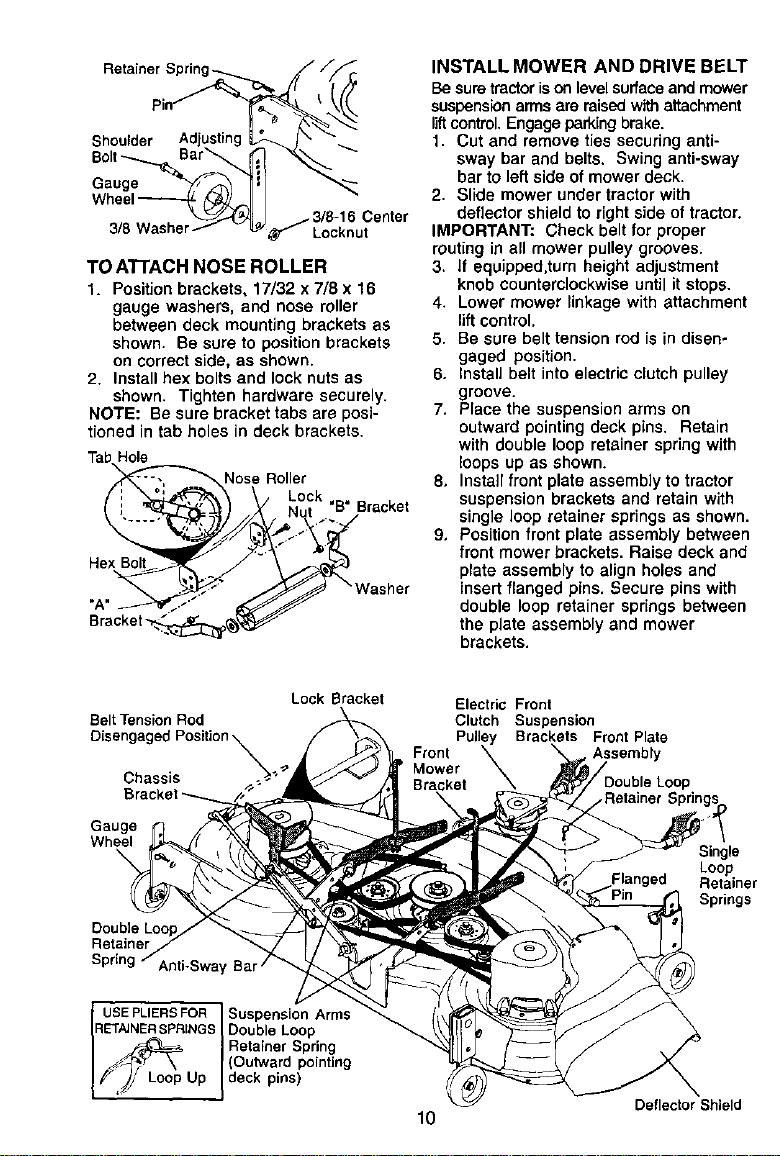
Shoulder Adjusting
Bolt Bar
Wheel_
_..._1 / 3/8-16 Center
3/8 Washer_ v _,_W__ Locknut
TO ATTACH NOSE ROLLER
1. Positionbrackets, 17/32 x 7/8 x 16
gauge washers, and nose roller
between deck mounting brackets as
shown. Be sure to positionbrackets
on correctside, as shown.
2. Installhex bolts and lock nuts as
shown. Tighten hardware securely.
NOTE: Be sure bracket tabs are posi-
tioned in tab holes in deck brackets.
TabHole
Nose Roller
Nut B Bracket
Hex olt o .-
"A" , Washer
S
INSTALL MOWER AND DRIVE BELT
Be suretractorisonlevelsurfaceand mower
suspensionarmsere raisedwithattachment
liftcontrol. Engageparkingbrake.
1. Cut and remove ties securing anti-
sway bar and belts. Swing anti-sway
bar to left side of mower deck.
2. Slide mower under tractor with
deflector shield to rightside of tractor.
IMPORTANT: Check belt for proper
routing in all mower pulley grooves.
3. If equipped.turn height adjustment
knob counterclockwiseuntil it stops.
4. Lower mower linkage with attachment
lift control.
5. Be sure belt tension rod is in disen-
gaged position.
6. Install belt into electric ctutch pulley
groove.
7, Place the suspension arms on
outward pointing deck pins. Retain
with double loop retainer spring with
loops up as shown.
8, Install front plate assembly to tractor
suspension brackets and retain with
single loop retainer springs as shown.
9, Position front plate assembly between
front mower brackets. Raise deck and
plate assembly to align holes and
insert ftanged pins. Secure pins with
double loop retainer springs between
the plate assembly and mower
brackets.
Belt Tension Rod
Disengaged Position XX_
Chassis . -";
Gauge
Wheel
\
Lock Bracket
Retainer
Spring Anti-Sway Bar /
USEPLIERSFOR Suspension Arms
RETAJNERSPRINGSDouble Loop
Retainer Spring
(Outward pointing
I f'Jj Loop Up I deck pins)
Electric Front
Clutch Suspension
Pulley Brackets Front Plate
Front
Mower
Bracket
10
Single
Loop
Retainer
Springs
Deflector Shield
NOTE: To assistin locating hole in
flanged pin, the hole in pin is inline with
notch on head of pin. If necessary, move
mower side-to-side to give space
between plate and mower brackets.
IMPORTANT: Check belt for proper
routing in all mower pulley grooves.
lO.Engage belt tension rod by pushing
rod intolockingbracket.
_kCAUTION: Belttensionred isspring
loaded. Have a tightgrip on red and
engage slowly.
11.Connect anti-sway bar to chassis
bracket under leftfootrest and retain
with double loop retainer spring.
12.If equipped, turn height adjustment
knob clockwiseto remove slack from
mower suspension.
13.Raise deck to highest position.
14.Adjust gauge wheels before operating
mower as shown in the Operation
sectionof this manual.
CHECK TIRE PRESSURE
The tires on your tractor were ovednflated
at the factory for shipping purposes.
Correct tire pressure is important for best
cutting performance.
• Reduce tire pressure to PSI shown in
"PRODUCT SPECIFICATIONS" section
of this manual.
CHECK MOWER LEVELNESS
For best cutting results, mower should be
properly leveled. See "TO LEVEL MOWER
HOUSING" in the Service and Adjustments
section of this manual.
CHECK FOR PROPER POSITION OF ALL
BELTS
See the figures that are shown for replac-
ing motion, mower drive, and mower blade
drive belts in the Service and Adjustments
section of this manual. Venfy that the belts
are routed correctly.
CHECK BRAKE SYSTEM
After you learn how to operate your tractor,
check to see that the brake is properly
adjusted. See "TO ADJUST BRAKE" in the
Service end AdjustmenLs section of this
manual.
I/CHECKLIST
Before you operate and enjoy your new
tractor,we wish to assurethat you receive
the best performance and satisfaction
from this quality product.
Please review the following checklist:
,/ All assembly instructionshave been
completed,
4" No remaining loose parts in carton.
/ Batteryis properly prepared and
charged.(Minimum 1 hour at 6 amps).
/ Seat is adjusted comfortablyand
tightened securely.
•/All tires are properlyinflated. (For
shipping purposes, the tires were
overinflated at the factory).
,/Be sure mower deck is properly leveled
side-to-sida/frent-to-rear for best cutting
results. (Tires must be properly inflated
for leveling).
,/Check mower and drive belts. Be sure
they are routed properly around pulleys
and inside all belt keepers.
,/Check wiring. See that all connections
are still secure and wires are properly
clamped.
While learning how to use your tractor,
pay extra attention to the following
important items:
/ Engine oil is at proper level.
Z"Fuel tank is filled with fresh, clean,
regular unleaded gasoline.
,/Become familiar with all controls - their
location and function. Operate them
before you start the engine.
#" Be sure brake system is in safe
operating condition.
11
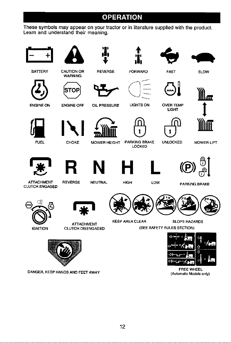
These symbolsmay appear on your tractor or in literature supplied withthe product.
Learn and understand their meaning.
BATTERY CAUTION OR REVERSE FORWARD FAST SLOW
WARNING
ENO,NEO.ENO,NEOFPO,LPnESSUaEL.G.TaONO%_MP [
FUEL CHOKE MOWER HEIGHT PARKING BRAKE UNLOCKED
LOCKED
MOWERLIF
r_'l R N H L
ATTACHMENT REVERSE NEUTRAL HIGH LOW
CLUTCH ENGAGED
®5I
PARKING BRAKE
A]7"ACHMENT
IGNITION CLUTCH DISENGAGED
DANGER, KEEP HANDS AND FEET AWAY
KEEP AREA CLEAR SLOPE HAZARDS
(SEE SAFETY RULES SECTION)
FREE WHEEL
(Automalic Models only)
12
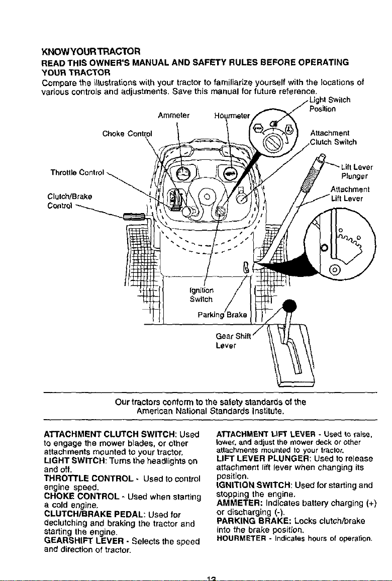
KNOW YOUR TRAC'rOR
READ THIS OWNER'S MANUAL AND SAFETY RULES BEFORE OPERATING
'YOURTR,a.CTOR
Compare the i_ustrations with your tractor to familiarize yourself with the locationsof
various controls and adjustments. Save this manual for future reference, tt Switch
Position
Ammeter Hourmeter
Attachment
Clutch Switch
Lever
ThroeleControl_ Plunger
Attachment
Clutch/Brake Lever
Lever
Our tractorsconformtothe safety standardsof the
American National Standards Institute.
ATTACHMENT CLUTCH SWITCH: Used
to engage the mower blades, or other
attachmentsmountedto your tractor.
LIGHT SWITCH: Turns the headtightson
andoff.
THROTTLE CONTROL- Used to control
engine speed,
CHOKE CONTROL - Used when starting
a cold engine.
CLUTCH/BRAKE PEDAL: Used for
deotutchlng and braking the tractor _.nd
starting the engine.
GEARSHIFT LEVER • Selects the speed
and direction of tractor.
ATTACHMENT LtFT LE_/ER - Used to raise,
io,,_er,_,nd adiust the mower deck or other
attachments mounted to your tractor,
LIFT LEVER PLUNGER: Used tOrelease
attachment lift lever when changing its
position.
IGNITION SWITCH: Used for starting and
stopping the engine.
AMMETIER: Indicates battery charging (+)
or diScharging (-).
PARKING BRAKE: Locks clutch/brake
(nto the brake position,
HOURMETER - Indicates hours of operation.
13
The operationof any tractor can result in foreign objectsthrown intothe
eyes, which can result in severe eye damage. Always wear safety glasses
or eye shields while operating your tractor or performing any adjustments
or repairs. We recommend a wide vision safety mask over spectacles, or
standard safety glasses.
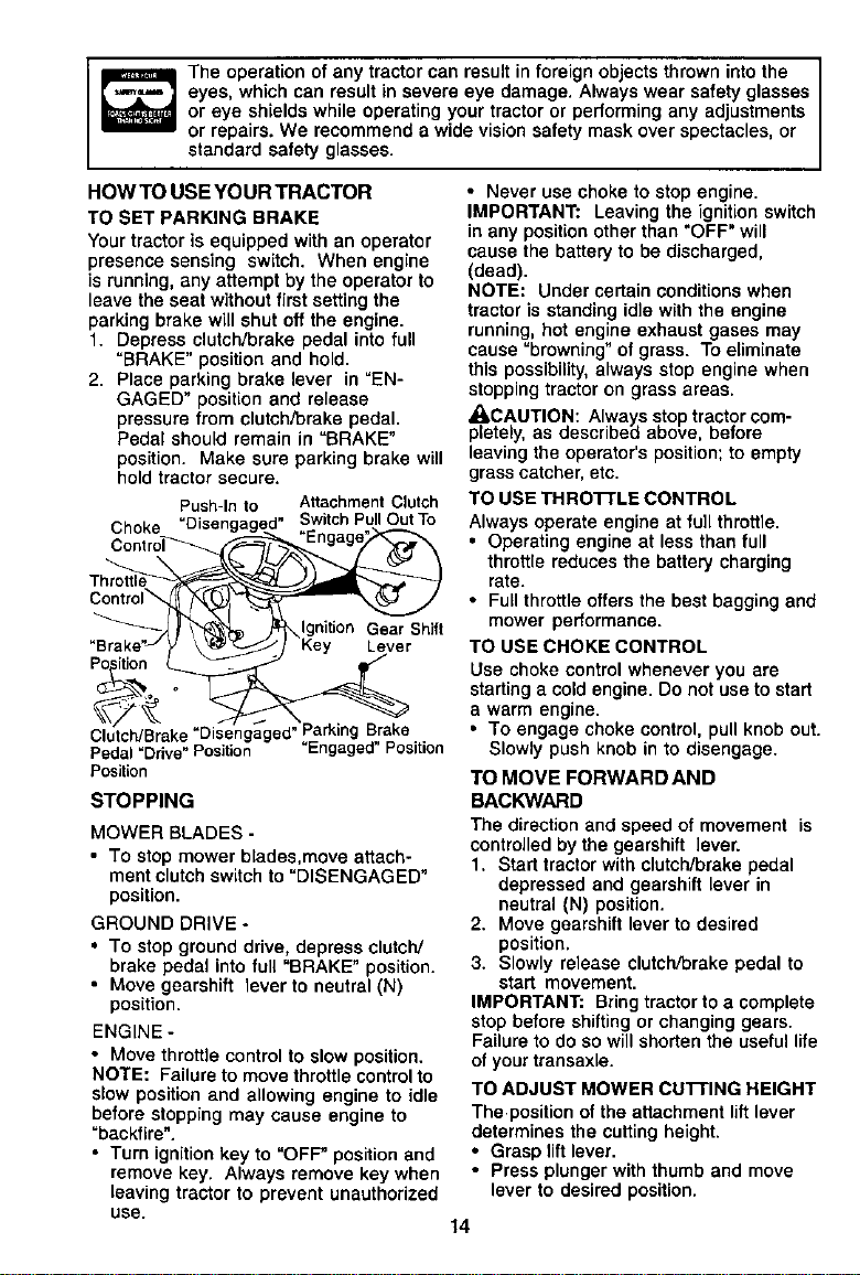
HOW TO USE YOUR TRACTOR
TO SET PARKING BRAKE
Yourtractor is equipped with an operator
presence sensing switch. When engine
is running,any attempt by the operator to
leave the seat withoutfirst settingthe
parking brakewill shut off the engine.
f. Depress clutch/brake pedal into full
=BRAKE" position and hold.
2. Place parking brake lever in =EN-
GAGED" positionand release
pressure from clutch/brake pedal.
Pedal should remain in =BRAKE"
position. Make sure parking brake will
hold tractorsecure.
Push-In to Attachment Clutch
Choke SwitchPullOutTo
Control_'_
Gear Shift
Lever
Po ition
Clutch/Brake_Disengaged"ParkingBrake
Pedal=Drive"Position "Engaged"Position
Position
STOPPING
MOWER BLADES -
• TO stop mower blades,move attach-
ment clutchswitch to =DISENGAGED"
position.
GROUND DRIVE -
• To stop ground drive, depress clutch/
brake pedal into full =BRAKE" position.
• Move gearshift lever to neutral (N)
position.
ENGINE -
• Move throttle control to slow position.
NOTE: Failure to move throttle controlto
slow position and allowing engine to idle
before stopping may cause engine to
=backfire".
• Turn ignition key to =OFF' position and
remove key. Always remove key when
leaving tractor to prevent unauthorized
use.
• Never use choke to stop engine.
IMPORTANT: Leaving the ignition switch
in any position other than "OFF" will
cause the battery to be discharged,
(dead).
NOTE: Under certain conditions when
tractor is standing idle with the engine
running, hot engine exhaust gases may
cause =browning" of grass. Toeliminate
this possibility, always stop engine when
stopping tractor on grass areas.
_I, CAUTION: Always stop tractor com-
pletely, as described above, before
leaving the operator's position; to empty
grass catcher, etc.
TO USE THRO'I-rLB CONTROL
Always operate engine at full throttle.
• Operating engine at less than full
throttle reduces the battery charging
rate.
• Full throttle offers the best bagging and
mower performance.
TO USE CHOKE CONTROL
Use choke control whenever you are
starting a cold engine. Do not use to start
a warm engine.
• To engage choke control, pull knob out.
Slowly push knob in to disengage.
TO MOVE FORWARD AND
BACKWARD
The directionand speed of movement is
controlledby the gearshift lever.
1. Start tractor with clutch/brakepedal
depressed and gearshift lever in
neutral (N) position.
2. Move gearshift lever to desired
position.
3. Slowly release clutch/brake pedal to
start movement.
IMPORTANT: Bring tractor to a complete
stop before shifting or changing gears.
Failure to do so will shorten the useful life
of your transaxle.
TO ADJUST MOWER CUTTING HEIGHT
The positionofthe attachmentliftlever
determines the cuttingheight.
• Grasp lift lever.
• Press plunger with thumband move
lever to desired position.
14
Thecuttingheightrangeisapproxi-
mateiy1-1/2to4".Theheightsare
measuredfromthegroundtotheblade
tipwiththeenginenotrunning.These
heightsareapproximateandmayvary
dependingupon soil conditions, height of
grass and types of grass being mowed.
• The average lawn should be cut to
approximately 2-1/2.inches during the
cool season and to over 3 inches
duringhot months, For healthier and
better looking lawns, mow often and
after moderate growth.
• For best cutting performance, grass
over 6 inches in height shouldbe
mowed twice. Make the first cut
relatively high; the second to desired
height.
TO ADJUST GAUGE WHEELS
Gauge wheels are properlyadjusted
when they are slightlyoff the ground
when mower is at the desired cutting
height in operatingposition. Gauge
wheels then keep the deck in proper
positionto help prevent scalpingin most
terrain conditions.
NOTE: Be sure tractoris on a flat level
surface.
1. Lower mower and adjust mowerto
desired cuttingheight.
2, Remove retainerspring and clevis pin
which secure each gauge wheel bar.
3. Lower gauge wheels to ground. Raise
gauge wheels slightly to align holes in
bracket and gauge wheel bar and
insert clevis pin. Gauge wheels
should be slightly off the ground.
4. Replace retainer spring into clevis pin.
5. Besure all gauge wheels are in the
same setting.
IMPORTANT: Be sure to readjust gauge
wheels if you change the cutting height
ofthe mowerdeck.
Retainer
Spring
Clevis
Pin
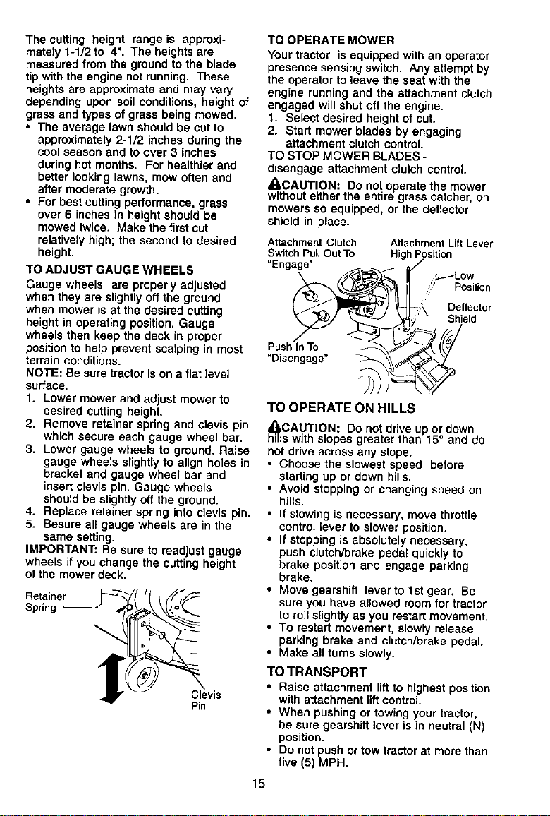
TO OPERATE MOWER
Your tractor is equipped with an operator
presence sensing switch. Any attempt by
the operator to leave the seat with the
engine running and the attachment clutch
engaged willshutoff the engine.
1. Select desired height of cut.
2. Start mower blades by engaging
attachment clutchcontrol
TO STOP MOWER BLADES -
disengage attachment clutch control.
_I,CAUTIONt Do not operate the mower
without either the entire grass catcher, on
mowers so equipped, or the deflector
shield inplace.
Attachment Clutch Attachment Lift Lever
Switch PuUOut To High Position
"Engage"
_.----Low
Position
Deflector
Shield
PushInTo
"Disengage"
1"O OPERATE ON HILLS
_,CAUTION: Do not drive up or down
hills with slopes greater than 15° and do
not drive across any slope,
• Choose the slowest speed before
starting up or down hills.
• Avoid stopping or changing speed on
hills.
• Ifslowingisnecesaa_/, move throttle
control lever to slower position.
• If stopping is absolutely necessary,
push clutch/brake pedal quickly to
brake position and engage parking
brake.
• Move gearshift lever to 1st gear, Be
sure you have allowed room for tractor
to rollslightlyas you restartmovement.
• To restart movement, slowly release
parking brake and clutch/brake pedal.
• Make all turns slowly.
TO TRANSPORT
• Raise attachment lift to highest position
with att_chreent liftcontrol.
• When pushing or towing your tractor,
be sure gearshift lever is in neutral (N)
position.
• Do notpush ortow tractorat more than
five (5) MPH.
15
NOTE:Toprotecthoodfromdamage
whentransportingyourtractoronatruck
oratrailer,besurehoodisclosedand
securedtotractor.Useanappropriate
meansoftyinghoodtotractor(rope,cord,
etc.).
TOWING CARTS AND OTHER A'rrACH-
MENTS
Tow only the attachments that are
recommended by and comply with
specificationsof the manufacturer of your
tractor.Use common sense when towing,
Too heavy of a load, while on a slope, is
dangerous. Tires can lose traction with
the ground and cause you to lose control
ofyour tractor.
BEFORE STARTING THE ENGINE
CHECK ENGINE OIL LEVEL
The engine in your tractor has been
shipped, from the factory, already filled
with summer weight oil.
1. Check engine oil with tractor on level
ground.
2. Unthread and remove oil fill cap/
dipstick; wipe oil off. Reinsert the
dipstick into the tube and rest oil fill
cap on the tube. Do not thread the
cap onto the tube. Remove and read
oil level. If necessary, add oil until
"FULL" mark on dipstick is reached.
Do not overfill.
• For cold weather operation you should
change oil for easier starting (See "OIL
VISCOSITY CHART" inthe Mainte-
nance section of this manual).
• To change engine oil, see the Mainte-
nance section in this manual.
ADD GASOLINE
• Fillfuel tank. Use fresh, clean, regular
unleaded gasoline with a minimumof
87 octane, (Use of leaded gasolinewill
increase carbon and lead oxide
deposits and reduce valve life). Do not
mix oil with gasoline. Purchase fuel in
quantitiesthat can be used within 30
days to assure fuel freshness.
IMPORTANT: When operatingin tem-
peratures below 32°F(0°C), use fresh,
clean winter grade gasoline to help
insure good cold weather starting.
_LWARNING: Experience indicatesthat
alcohol blended fuels (called gasohol or
using ethanol or methanol) can attract
moisture which leads to separation and
formation of acids during storage. Acidic
gas can damage the fuel system of an
engine while in storage. To avoid engine
problems, the fuel system should be
emptied before storage of 30 days or
longer. Drain the gas tank, start the
engine and let it run until the fuel lines
and carburetor are empty. Usa fresh fuel
next season. See Storage Instructions for
additional information. Never use engine
or carburetor cleaner products in the fuel
tank or permanent damage may occur.
_,CAUTION: Fillto bottom of gastank
filler neck. Do not overfill.Wipe offany
spilledoil or fuel. Do not store, spillor use
gasoline near an open flame.
TO START ENGINE
When starting the engine for the first time
or if the engine has run out of fuel, it will
take extra cranking time to move fuel from
the tank to the engine.
1. Sit on seat in operating position,
depress clutch/brake pedal and set
parking brake.
2. Place gear shift lever in neutral (N)
position.
3. Move attachment clutch to "DISEN-
GAGED" position.
4. Move throttle control to fast position
5. Pull choke control out for a cold
engine start attempt. For a warm
engine start attempt the choke control
may not be needed.
NOTE: Before starting, read the warm and
cold starting procedures below.
6. Insert key into ignition and turn key
clockwise to "START" positionand
release key as soon as engine starts.
Do not run starter continuouslyfor
more than fifteen seconds per minute.
If the engine does not start after
several attempts, push choke control
in, wait a few minutes and try again. If
engine still does not start, pull the
choke controlout and retry.
WARM WEATHER STARTING (50° F and
above)
7. When engine starts, slowly push
choke control in until the engine
begins to run smoothly. If the engine
starts to run roughly,pull the choke
control out slightly for a few seconds
end then continue to push the control
in slowly.
16
• The attachments and ground drive can
now be used. If the engine does not
accept the load, restart the engine and
allow it to warm up for one minute
using the choke as described above.
COLD WEATHER STARTING (50° F and
below)
7. When engine starts, slowly push
choke control in until the engine
begins to run smoothly. Continue to
push the choke control in small steps
allowing the engine to accept small
changes in speed and load, until the
choke control is fully in. If the engine
starts to run roughly,pull the choke
controloutslightlyfor a few seconds
and then continueto push the control
in slowly. This may require an engine
warm-up periodfrom several seconds
to several minutes,depending on the
temperature.
• The attachments can he used during
the engine warm-up period and may
require the choke controlbe pulled out
slightly.
NOTE: ifata high altitude(above3000feet)
orincoldtemperatures(below32 F)the
carburetorfuel mixturemay needtobe
adjustedfor best engineperformance.See
"TO ADJUST CARBURETOR"inthe Service
andAdjustments sectionof this manual.
MOWING TIPS
• Mower should be properly leveled for
best mowing performance. See "TO
LEVEL MOWER HOUSING" inthe
Service and Adjustments section of this
manual.
• The left hand side of mower should be
used for trimming.
• Drive so that clippings are discharged
onto the area that has been cut. Have
the cut area to the right of the tractor.
This will result in a more even distribu-
tion of clippings and more uniform
cutting.
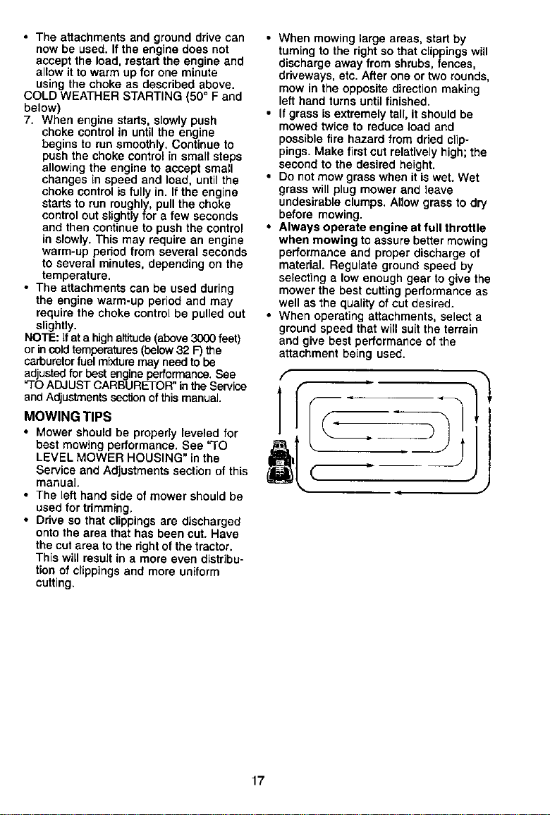
• When mowing large areas, start by
turningto the right so that clippings will
discharge away from shrubs, fences,
driveways, etc. After one or two rounds,
mow in the opposite direction making
le_thand turns untilfinished.
• If grass isextremely tall, it should be
mowed twice to reduce load and
possible fire hazard from dried clip-
pings. Make first cu_.relatively high;'the
second to the desired height.
• Do notmow grass when it iswet. Wet
grass will plug mower and leave
undesirable clumps. Allow grass to d_J
before mowing.
• Always operate engine at full throttle
when mowing toassure better mowing
performance and proper discharge of
material. Regulate groundspeed by
selecting a low enough gear to give the
mower the best cuttingperformance as
well as the quality ofcut desired.
• When operating attachments, select a
groundspeed that willsuit the terrain
and give bestperformance of the
attachment being used.
f
17
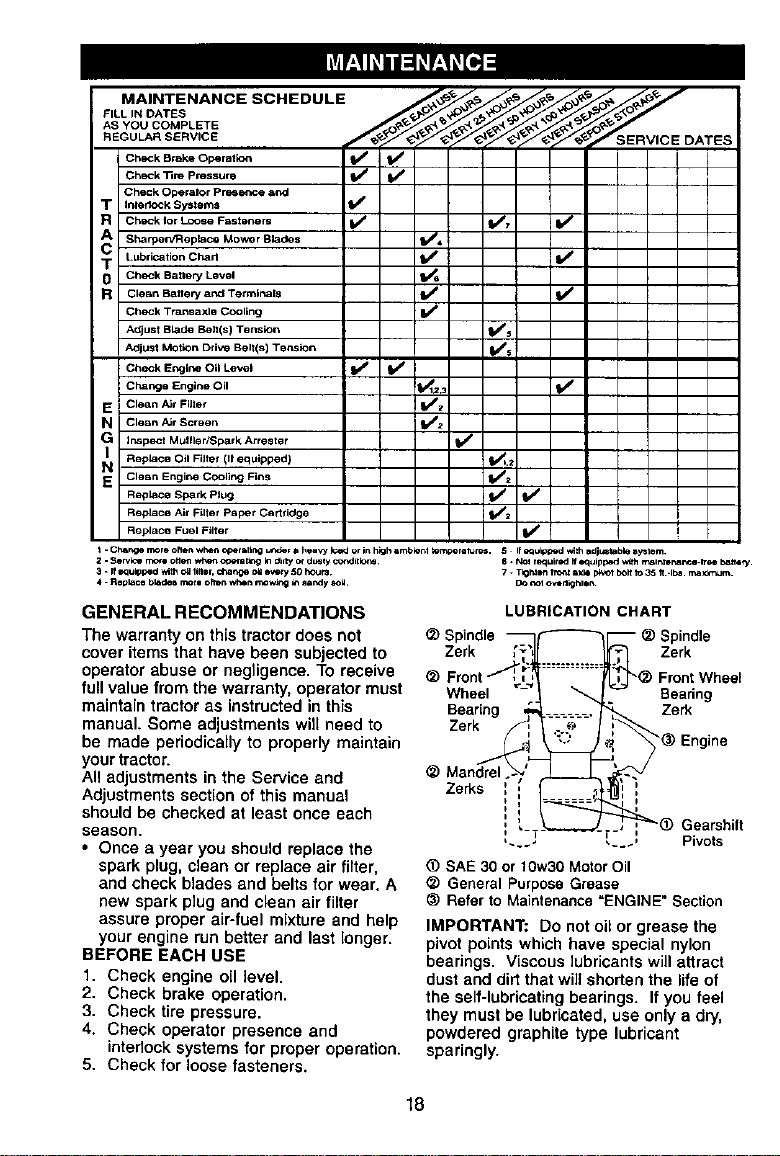
MAINTENANCE SCHEDULE _. _ _. _ _'_
AS YOU COMPLETE _ R.__ _.'_R._-_9, _- _-_
Check Brake Operatio_ _ V'
Check _re Pressure V' V'
Check Operelor Pre_ aP, d
T Inledock Systems f_
R Check lot Lco,e Fast .... V + V*_, V"
SharpelVRe place Mowor Bla_s _4
T Lubrication Chart _ I_
0 Check Battery Level I_
R Clean BatUery and Terminals II/
Check Transexle Cooling If
Adjust Blade Be_(s) Tension Ills
Adjust Motion Drive Belttm) Tension V' s
Check Engine O_1 Level I_
Chang== Engine Oil _123
E Clean Air Filter V'z
N Clean A_¢ Screen _2
G imspec t Mulller_parkArrester
Replace Oil Filter (11 equipped) _,2
N Clean Engine Cooling Fins p,_=
Replace Spark Plug I_ t# #
i
Replace Air Filter Paper Cartridge _2 I
Replace Fuel Filter V* I
_'_SERVICE DATES
I
I
I
I
I-Ch_r_emoreohenw_r, oper==llr.gu,_derahea',71_orinhighamb_erbt_re_. 5 If_ukop*d,_thldj_ble_ystem
2. Service rr_rl omen whet, oCemtog k__ny ot dully cor,dht_
3. If=quipped wlth ca liner, charge ca o_=¢y 5OhouPa
4. RepLace bk_de6 morl often wt_n rnow_g _ s**t_y _ca,
8 * N_ rt_+uir_d ff _,qukp_ed w_h rr_ir,4en_n_e.lre_ b_t,_y.
7. T+gM_ f rot4 sxle pb_Olboif io 35 tt..Ibe, rea xk*_Jrr+.
DO _t o_tlkd, mn
GENERAL RECOMMENDATIONS
The warranty on this tractor does not
cover itemsthat have been subjected to
operatorabuse or negligence. To receive
fullvalue from the warranty,operator must
maintain tractor as instructedin this
manual. Some adjustments will need to
be made periodicallyto properly maintain
yourtractor.
All adjustments in the Service and
Adjustmentssection of this manual
should be checked at least once each
season.
• Once a year you should replace the
spark plug, clean or replace air filter,
and check blades and belts for wear. A
new spark plugand clean air filter
assure proper air-fuel mixture and help
your engine run better and last longer.
BEFORE EACH USE
1. Check engine off level.
2. Check brake operation.
3. Check tire pressure.
4. Check operator presence and
interlocksystems for proper operation.
5. Check for loose fasteners.
LUBRICATION CHART
Spindle _/_---"_1-- _ Spindle
Zerk _.... _._ =__,;- Zerk
Front (_ FrontWheel
Wheel "_ "_ =_-> Beadng
Bearng • Zerk
Zerk__ i
_) Engne
_) Mandrel_ _
Zerks !_ il
.
1 _ Gearsh
-/-
_..., __..* Plvo s
SAE 30 or 10w30 Motor Oil
General Purpose Grease
(_ Refer to Maintenance =ENGINE" Section
IMPORTANT: Do not oil or grease the
pivot points whichhave special nylon
bearings. Viscouslubricants willattract
dust and dirt thatwillshorten the life of
the self-lubricatingbearings. If you feel
they must be lubricated,use only a dry,
powdered graphite type lubricant
sparingly.
18
TRACTOR
Always observe safety rules when
performing any maintenance.
BRAKE OPERATION
If tractor requires morethan six (6) feet
stoppingdistance at high speed in
highestgear, then brake must be ad-
justed. (See "TO ADJUST BRAKE" in the
Serviceand Adjustments sectionof this
manual).
TIRES
• Maintain proper air pressure in all tires
(See =PRODUCT SPECIFICATIONS"
section of this manual).
• Keep tires free of gasoline, oil, or insect
control chemicals which can harm
rubber.
• Avoid stumps, stones, deep ruts, sharp
objects and other hazards that may
cause tire damage.
NOTE: To sea[ tire punctures and prevent
flat tires due to slow leaks, tire sealant
may be purchased from your local parts
dealer."13resealant also prevents tire dry
rot and corrosion.
OPERATOR PRESENCE SYSTEM
Be sure that operator presence and
interlock systems are working properly. If
your tractor does not function as de-
scribed below, repair the problem
immediately.
• The engine should not start unless the
brake pedal is fully depressed and
attachment clutch control is in the
disengaged position.
• When the engine is running, any
attempt by the operator to leave the
seat without first setting the parking
brake should shut off the engine.
• When the engine is runningand the
attachment clutchis engaged, any
attempt by the operator to leave the
seat should shut off the engine.
• The attachment clutchshould never
operate unless the operator is in the
seat.
BLADE CARE
For bestresults mower blades must be
keptsharp. Replace bent or damaged
blades.
BLADE REMOVAL
1. Raise mower to highest positionto
allow access to blades.
NOTE: Protectyour handswith gloves
and/orwrap blade with heavy cloth.
2. Remove blade bolt by turning counter-
clockwise.
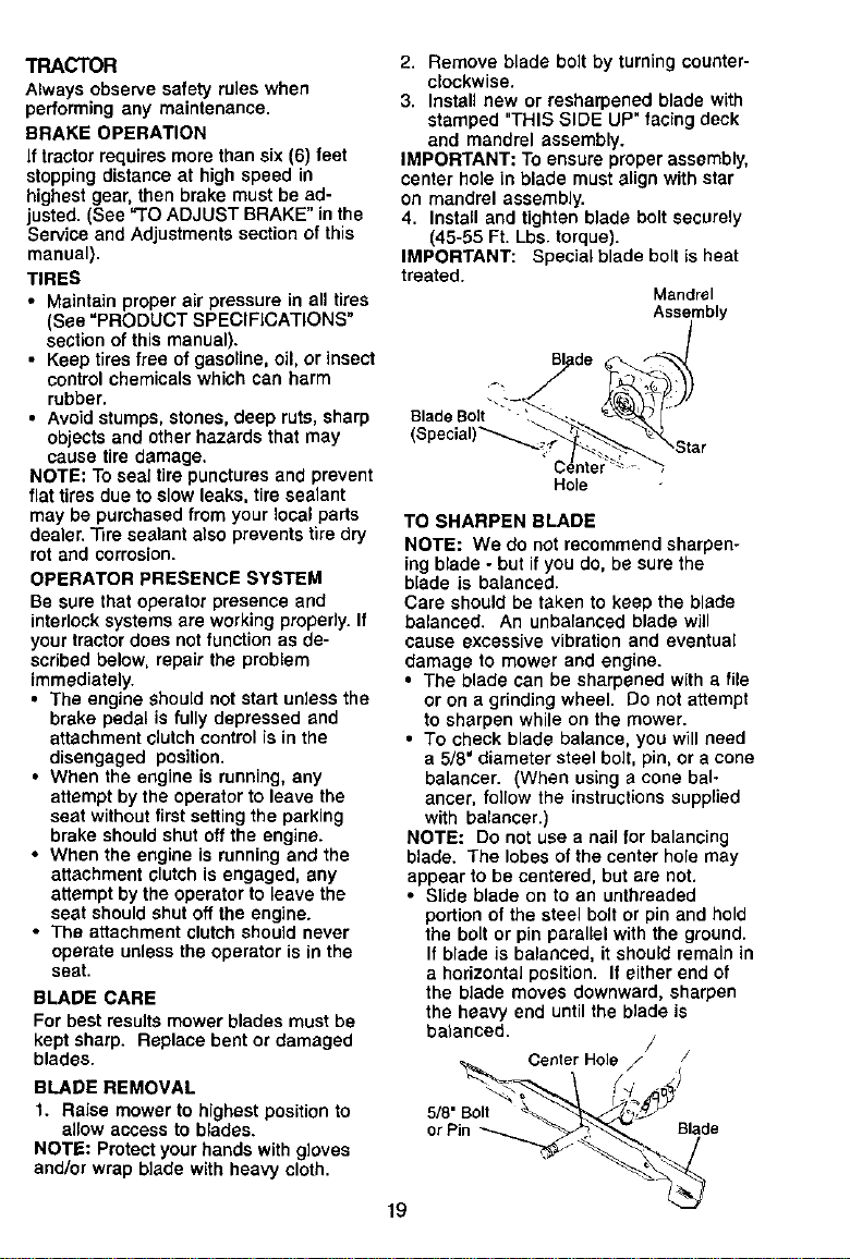
3. Install new or resharpened blade with
stamped "THIS SIDE UP" facing deck
and mandrel assembly.
IMPORTANT: To ensure proper assembly,
center hole in blade must align with star
on mandrel assembly.
4. InstaU and tighten blade bolt securely
(45-55 Ft. Lbs. torque).
IMPORTANT: Special blade bolt is heat
treated.
Mandrel
Assembly
gl/ade _
Hole
19
TO SHARPEN BLADE
NOTE: We do not recommend sharpen-
ing blade - but if youde, be sure the
blade is balanced.
Care should be taken to keep the blade
balanced. An unbalanced blade will
cause excessive vibration and eventual
damage to mower and engine.
• The blade can be sharpened with a file
or on a grinding wheel. Do not attempt
to sharpen while on the mower.
• To check blade balance, you will need
a 5/8' diameter steel bolt, pin, or a cone
balancer. (When using a cone bal-
ancer, follow the instructions supplied
with balancer.)
NOTE: Do not use a nail for balancing
blade. The lobes of the center hole may
appear to be centered, but are not.
• Slide blade on to an untbreaded
portion of the steel bolt or pin and hold
the belt or pin parallel with the ground.
If blade is balanced, it should remain in
a horizontal position. If either end of
the blade moves downward, sharpen
the heavy end until the blade is
balanced.
/
Center Hole / /
BATTERY
Yourtractor has a battery chargingsystem
which issufficientfor normal use. How-
ever, periodic chargingof the battery with
an automotivecharger will extend its life.
• Keep battery and terminals clean.
• Keep battery bolts tight,
• Keep small vent holes open.
• Recharge at 6-10 amperes for 1 hour.
NOTE: The original equipment battery on
your tractor is maintenance free. Do not
attempt to open or remove caps or covers.
Adding or checking level of electrolyte is
not necessary.
TO CLEAN BATTERY AND TERMINALS
Corrosion and dirt on the battery and
terminals can cause the battery to "leak"
power.
1. Remove terminal guard.
2. Disconnect BLACK battery cable first
then RED battery cable and remove
battery from tractor.
3. Rinse the battery with plain water and
dry.
4. C_ean terminals and battery cable
ends with wire brush until bright.
5. Coat terminals with grease or petro-
leum jelly.
6. Reinstall battery (See =REPLACING
BATTERY" in the SERVICE AND
ADJUSTMENTS section of this
manual).
V-BELTS
Check V-belts for deterioration and wear
after lOg hours of operation and replace
if necessary. The belts are not adjustable.
Replace belts if they begin to slip from
wear.
TRANSAXLE COOLING
Keep transaxle free from build-upof dirt
and chaff whichcan restrictcooling.
ENGINE
LUBRICATION
Only use high quality detergent oUrated
withAPI serviceclassificationSF-SJ.
Select the oil's SAE viscosity grade
according to your expected operating
temperature.
Change the oil after every 50 hours of
operation or at least once a year if the
tractor is not used for 50 hours in one
year.
Check the crankcase oil level before
starting the engine and after each eight
(8) hours of operation, Tighten oil fill cap/
dipstick securely each time you check the
oil level.
TO CHANGE ENGINE OiL
Determine temperature range expected
before oil change. All oil must meet API
service classification SF-SJ.
• Be sure tractor is on level surface.
• Oil will drain more freely when warm.
• Catch oil in a suitable container.
1. Remove oil fill cap/dipstick. Be careful
not to allow dirt to enter the engine
when changing oil
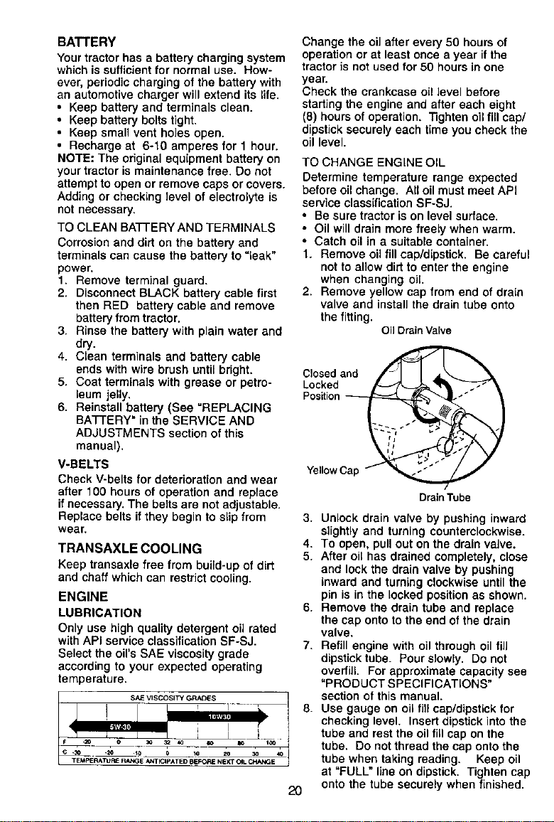
2. Remove yellow cap from end of drain
valve and install the draintube onto
the fitting.
OilDrainValve
Closed and
Locked
Position
Yellow Ca
2O
DrainTube
3. Unlock drain valve by pushing inward
slightly and turning counterclockwise.
4. To open, pull out on the drain valve.
5. After oil has drained completely, close
and lock the drain valve by pushing
inward and turning clockwise until the
pin is in the locked position as shown.
6. Remove the drain tube and replace
the cap onto to the end of the drain
valve.
7. Refill engine with oil through oil fill
dipstick tube. Pour slowly. Do not
overfill. For approximate capacity see
"PRODUCT SPECIFICATIONS"
section of this manual.
8. Use gauge on oil fill cap/dipstick for
checking level. Insert dipstick into the
tube and rest the oil fill cap on the
tube. DOnot thread the cap onto the
tube when taking reading. Keep oil
at "FULL" line on dipstick, Tighten cap
onto the tube securely when finished.
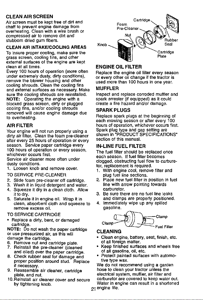
CLEAN AIR SCREEN
Air screen must be kept free ofdirt and
chaff to prevent engine damage from
overheating. Clean with a wire brush or
compressed air to remove dirt and
stubborndried gum fibers.
CLEAN AIR INTAKE/COOLING AREAS
To insure propercooling, make sure the
grass screen, cooling fins, and other
external surfaces of the engine are kept
clean at all times.
Every 100 hours of operation (more often
under extremely dusty, dirty conditions),
remove the blower housing and other
cooling shrouds. Clean the cooling fins
and external surfaces as necessary. Make
sure the cooling shrouds are reinstalled.
NOTE: Operating the engine with a
blocked grass screen, dirty or plugged
cooling fins, and/or cooling shrouds
removed will cause engine damage due
to overheating.
AIR FILTER
Your engine will not run properly usinga
dirty air filter. Clean the foam pre-deaner
after every 25 hours of operation or every
season. Service paper cartridge every
100 hours of operation or every season,
whichever occurs first.
Service air cleaner more often under
dusty conditions.
1. Loosen knob and remove cover.
TO SERVICE PRE-CLEANER
2. Slide foam pre-cleaner off cartridge.
3. Wash it in liquid detergent and water.
4. Squeeze it dry in a clean cloth. Allow
it to dry.
5. Saturate it in engine oil. Wrap it in
clean, absorbent cloth and squeeze to
remove excess oil.
TO SERVICE CARTRIDGE
• Replace a dirty, bent, or damaged
cartridge.
NOTE: Do not wash the paper cartridge
or use pressurized air, as this will
damage the cartridge.
6. Remove nut and cartridge plate.
7. Reinstall the pre-cleaner (cleaned
and oiled) over the paper cartridge.
8. Check rubber seal for damage and
proper position around stud. Replace
if necessary.
9. Reassemble air cleaner, cartridge
plate, and nut.
10.Reinstall air cleaner cover and secure
by tightening knob.
Knob
Foam
Nut
Rubber
Seal
:artridge
Plate
ENGINE OIL FILTER
Replace the engine oil filter every season
or every other oil change if the tractor is
used more than 100 hours in one year.
MUFFLER
Inspect and replace corrodedmuffler and
spark arrester (ifequipped) as it could
create a fire hazard and/or damage.
SPARK PLUGS
Replace spark plugs at the beginning of
each mowing season or after every 100
hours of operation, whichever occurs first.
Spark plug type and gap setting are
shown in "PRODUCT SPECIFICATIONS"
section of this manual.
IN-LINE FUEL FILTER
The fuel filter should be replaced once
each season. Iffuel filter becomes
clogged, obstructing fuel flow to carbure-
tor, replacement is required.
1. With engine cool, remove filter and
plug fuel line sections.
2. Place new fuel filter in position in fuel
line with arrow pointing towards
carburetor.
3. Be sure there are no fuel line leaks
and clamps are properly positioned.
4. Immediately wipe up any spilled
gasoline.
Clamp
Clamp/ _ FuelFilter
CLEANING
• Clean engine, battery, seat, finish, etc.
of all foreign matter.
• Keep finished surfaces and wheels free
of ell gasoline,oil, etc.
• Protectpainted surfaces with automo-
tive type wax.
We do not recommend usinga garden
hoseto clean your tractor unlessthe
electrical system, muffler,air filter and
carburetor are covered to keep water out.
Water in engine can result in e shortened
21 engine life,
_i CAUTION: BEFORE PERFORMING ANY SERVICE OR ADJUSTMENTS:
1. Depress clutch/brake pedal fullyand set parking brake.
2. Place gearshift lever in neutral (N) position.
3. Place attachment clutch in "DISENGAGED" position.
4. Turn ignitionkey "OFF" and remove key.
5. Make sure the blades and all moving partshave completelystopped.
6. Disconnectspark plug wire from spark plug and place wire where it cannot
come in contact with plug.
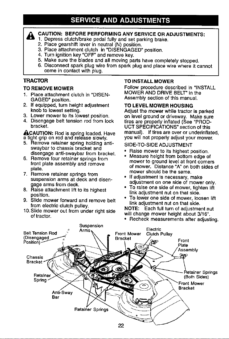
TRACTOR
TO REMOVE MOWER
1. Place attachment clutch in "DISEN-
GAGED" position.
2. If equipped, turn height adjustment
knobto lowest setting.
3. Lower mower to its lowest position.
4. Disengage belt tension rod from lock
bracket.
_CAUTION: Rod is spring loaded. Have
a tight grip on rod and release slowly.
5. Remove retainer spring holding anti-
swaybarto chassis bracket and
disengage anti-swaybar from bracket.
6. Remove four retainer springsfrom
front plate assembly and remove
plate.
7. Remove retainer springsfrom
suspensionarms at deck and disen-
gage arms from deck.
8. Raise attachment lift to its highest
position.
9. Slide mower forward and remove belt
from electric clutchpulley.
t0.Slide mower out from under rightside
oftractor.
TO INSTALL MOWER
Follow procedure described in "INSTALL
MOWER AND DRIVE BELT" in the
Assembly section of this manual.
TO LEVEL MOWER HOUSING
Adjustthe mower while tractor isparked
on level groundor driveway. Make sure
tires are properlyinflated (See =PROD-
UCT SPECIFICATIONS" section ofthis
manual). If tires are overor underinflated,
you will net properlyadjust your mower.
SIDE-TO-SIDE ADJUSTMENT
• Raise mower to its highestposition.
• Measure height from bottomedge of
mowerto groundlevel at front corners
of mower. Distance "A"on both sides of
mower should be the same.
• If adjustmentis necessary, make
adjustment on one side of mower only.
• To raise one side of mower,tighten lift
linkadjustmentnut onthat side.
• To lower one side of mower, loosen lift
linkadjustmentnut onthat side.
NOTE: Each fullturn of adjustmentnut
will change mower height about 3/16".
• Recheck measurements after adjusting.
Suspension
Electric
Belt Tension Rod " Front Mower Clutch Pulley
(Disengage6_-_,, / Bracket
Position)_ Front
Plate
Chassis
Retainer
Sprin!
Anti-Sway
Bar
Springs
er Springs
(Both Sides)
Bracket
22
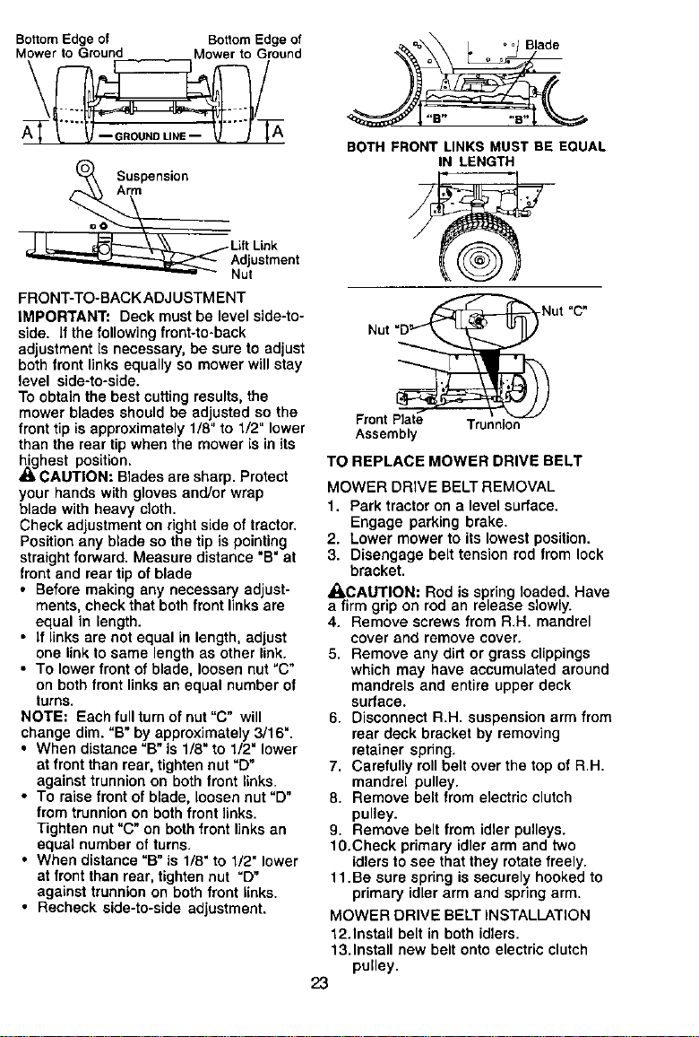
BottomEdgeof BottomEdgeof
Mowerto Ground Mower to Ground
\ /
Suspension
Arm
OO --
LiftLink
Adjustment
Nut
FRONT-TO-BACK ADJUSTMENT
IMPORTANT: Deck must be level side-to-
side. If the following front-to-back
adjustment is necessary, be sure to adjust
both front links equally so mower will stay
level side-to-side.
To obtain the best cutting results, the
mower blades should be adjusted so the
front tip is approximately 1/8" to 1/2" lower
than the rear tip when the mower is in its
highest position.
CAUTION: Blades are sharp. Protect
your hands with gloves and/or wrap
blade with heavy cloth.
Check adjustment on right side of tractor.
Position any blade so the tip is pointing
straight forward. Measure distance "B" at
front and rear tip of blade
• Before making any necessary adjust-
ments, check that both front links ere
equal in length.
• If links are not equal in length, adjust
one link to same length as other link.
• To lower front of blade, loosen nut"C"
on both front links an equal number of
turns.
NOTE: Each full turn of nut "C" will
change dim. "B" by approximately 3/16".
• When distance "B" is 1/8" to 1/2" lower
at front than rear, tighten nut =D"
against trunnion on both front links.
• To raise front of blade, loosen nut "D"
from trunnion on both front links.
Tighten nut "C" on both front links an
equal number of turns.
• When distance "B" is 1/8" to 1/2" lower
st front than rear, tighten nut "D"
against trunnion on both front links.
• Recheck side-to-side adjustment.
BOTHFRONT LINKS MUSTBE EQUAL
IN LENGTH
Nut 'D_ ut "C"
Front Plate Trunnion
Assembly
TO REPLACE MOWER DRIVE BELT
MOWER DRIVE BELT REMOVAL
1. Park tractor on a level surface.
Engage parking brake.
2. Lower mower to its lowest position.
3. Disengage belt tension rod from lock
bracket.
_I,CAUTION: Rod is spring loaded. Have
a firmgrip on rod an release slowly.
4. Remove screws from R.H. mandrel
cover and remove cover.
5. Remove any dirt or grass clippings
which may have accumulated around
mandrels and entire upper deck
surface.
6. Disconnect R.H. suspension arm from
rear deck bracket by removing
retainer spring.
7. Carefully roll belt over the top of R.H.
mandrel pulley.
8. Remove belt from electric clutch
pulley.
9. Remove belt from idler pulleys.
10.Check primary idler arm and two
idlers to see that they rotate freely.
11.Be sure spring is securely hooked to
primary idler arm and spring arm.
MOWER DRIVE BELT INSTALLATION
12.Install belt in both idlers.
13.Install new belt onto electric clutch
pulley.
23
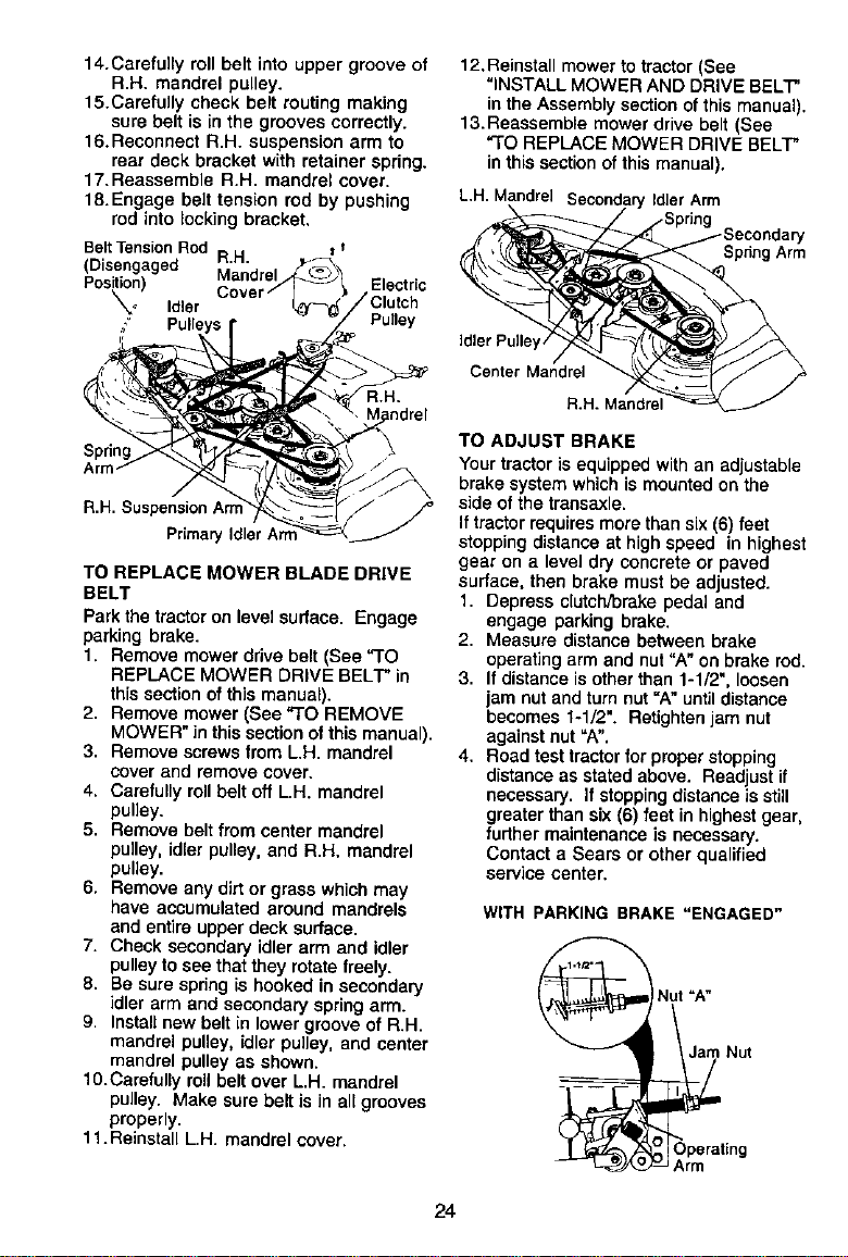
14.Carefullyrollbeltintouppergrooveof
R.H.mandrelpulley.
15.Carefu_tycheck bert routingmaking
sure belt is in the grooves correctly.
16.Reconnect R.H. suspension arm to
rear deck bracket with retainer spring.
17.Reassemble R.H. mandrel cover.
18.Engage belt tension rod by pushing
rod into locking bracket.
Belt_ensionRod R.H. =1
(Disengaged Mandrel
Position) Electric
_._ Idler /Clutch
' PUll Pul_ey
12. Reinstall mower to tractor (See
"INSTALL MOWER AND DRIVE BELT"
in the Assembly sectionof this manual).
13,Reassemble mowerdrive belt (See
"TO REPLACE MOWER DRIVE BELT"
inthis sectionofthismanual).
L,H. Mandrel Secondary Idler Arm
Y
Sp_ng Arm
Spdng
R.H. Suspension Am
Priraary [alter
TO REPLACE MOWER BLADE DRIVE
BELT
Parkthe tractoron level surface. Engage
parking brake.
1. Remove mowerdrive belt (See "TO
REPLACE MOWER DRIVE BELT"in
this sectionofthis manual).
2. Remove mower (See "TO REMOVE
MOWER" inthis sectionofthis manual).
3. Remove screwsfrom L.H. mandrel
cover and remove cover.
4, Carefullyroll belt off L.H. mandrel
pulley.
5. Remove bertfrom center mandrel
pulley, idler pulley, and R.H. mandrel
pulley.
6. Remove any dirt or grass which may
have accumulated around mandrels
and entire upper deck surface.
7. Check secondaryidler arm and idler
pulley to see that they rotate freely.
8. Be surespdng is hooked in secondary
idler arm and secondary spring arm.
9. Install new belt in lower grooveof R.H.
mandrel pulley, idler pulley, and center
mandrel pulley as shown.
10.Carefufly roll belt over L.H. mandrel
pulley. Make sure belt is in all grooves
properly.
11.Reinstall L.H. mandrel cover.
Center Mandrel
R.H. Mendel
TO ADJUST BRAKE
Your tractoris equipped withan adiustabte
brake system whichismounted on the
side ofthe transaxle.
Iftractorrequiresmorethan six(6) feet
stopping distance at high speed in highest
gear on a level dry concrete or paved
surface, then brake must be adjusted.
1. Depress clutch/brakepedal and
engage parking brake.
2. Measure distance between brake
operating arm and nut "A" on brake rod.
3. If distance is other than 1-1/2", loosen
jam nut and turn nut "A" until distance
becomes 1-1/2". Retighten jam nut
against nut "A".
4, Road test tractorforproper stopping
distance as statedabove. Readjustif
necessary. If stoppingdistance is still
greaterthan six (6) feet in highestgear,
further maintenanceis necessary,
Contact a Sears or other qualified
service center,
WITH PARKING BRAKE "ENGAGED"
Nut =A"
J_ Nut
Operating
Arm
24
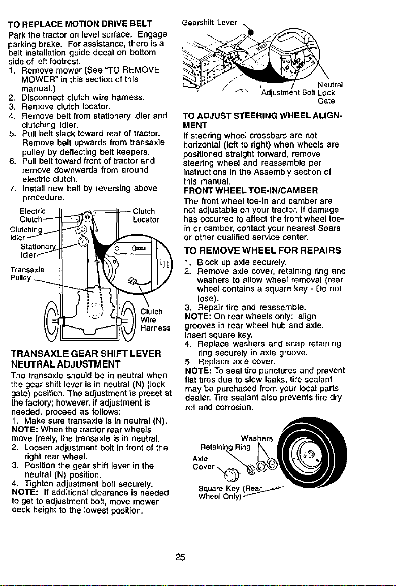
TO REPLACE MOTION DRIVE BELT
Park the tractoron levelsurface. Engage
parkingbrake. For assistance,there isa
belt installationguide decal on bottom
side of leftfootrest.
1. Remove mower (See "TO REMOVE
MOWER" inthis sectionof this
manual.)
2. Disconnect clutch wire harness.
3. Remove clutch Iocator.
4. Remove belt from stationary idler and
clutching idler.
5. Pull belt slack toward rear of tractor.
Remove belt upwards from transaxle
pulley by deflecting belt keepers.
6. Pull belt toward front of tractor and
remove downwards from around
electric clutch.
7. Install new belt by reversing above
procedure.
Electric
Clutch_
Clutching
Idler_
Stati_.
Idler
Transaxle
Pulley ._.......
_ _ Clutchr
_ Harness
TRANSAXLE GEAR SHIFT LEVER
NEUTRAL ADJUSTMENT
The transaxle should be in neutralwhen
the gear shiftlever is in neutral(N) (lock
gate) position. The adjustment is preset at
the factory; however, if adjustment is
needed, proceed as follows:
1. Make sure transaxle is in neutral (N).
NOTE: When the tractorrear wheels
move freely, the transaxle isin neutral.
2. Loosen adjustment boltin front ofthe
right rear wheel.
3. Positionthe gear shift lever in the
neutral (N) position.
4. Tighten adjustmentbctt securely.
NOTE: If additionalclearance is needed
toget to adjustmentbolt, move mower
deck heightto the lowest position.
Gearshift Lever
Gate
TO ADJUST STEERING WHEEL ALIGN-
MENT
If steering wheel crossbars are not
horizontal(left to right)when wheels are
positioned straight fon_ard, remove
steering wheel and reassemble per
instructions in the Assembly sectionof
this manual.
FRONT WHEEL TOE-IN/CAMBER
The front wheel toe-in and camber are
notadjustable on your tractor.If damage
has occurred toaffect the front wheel toe-
in or camber,contactyour nearestSears
or other qualifiedservice center.
TO REMOVE WHEEL FOR REPAIRS
1. Block up axle securely,
2. Remove axle cover, retaining ring and
washers to allow wheel removal (rear
wheel contains a square key - Do not
lose).
3. Repair tire and reassemble.
NOTE: On rear wheels only: align
grooves in rear wheel huband axle.
Insert square key.
4. Replace washers and snap retaining
ring securely in axle groove.
5. Replace axle cover.
NOTE: To seal tire puncturesand prevent
flat tires due toslow leaks, tire sealant
may be purchased from your local parts
dealer.Tire sealant also prevents tire dry
rot and corrosion.
Washers "__
RetainingRing kII//F_lll
Cover
SquareKey(ReajL..._=_ -,_,-_w--
Wheel Only)
25
TO START ENGINE WITH AWEAK
BA'rTERY
_,CAUTION: Lead-acid batteries
generate explosive gases. Keep sparks,
flame and smoking materials away from
batteries. Always wear eye protection
when around batteries.
Ifyour battery is too weak to start the
engine, it should be recharged. (See
"BATIERY" in the MAINTENANCE
section of this manual).
If "jumper cables" are used for emergency
starting, follow this procedure:
IMPORTANT: Your tractor is equipped
with a 12 volt negative grounded system.
The other vehical must also be a 12 volt
negative grounded system. Do not use
your tractor battery to start other vehicles.
TO ATTACH JUMPER CABLES -
1. Connect each end of the RED cable to
the POSITIVE (+) terminal of each
battery, taking care not to short
against chassis.
2. Connect one end of the BLACK cable
to the NEGATIVE (-) terminal of fully
charged battery.
3. Connect the other end of the BLACK
cable to good CHASSIS GROUND,
away from fuel tank and battery.
TO REMOVE CABLES, REVERSE
ORDER -
1. BLACK cable first from chassis and
then from the fully charged battery.
2. RED cable last from both batteries.
"Positive"(+) "Negative" (-)
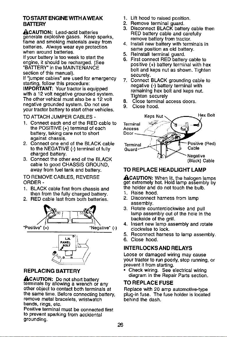
REPLACING BAI-I'E RY
_CAUTION: Do not short battery
terminals by allowing a wrench or any
other object to contact both terminals at
the same time. Before connecting battery,
remove metal bracelets, wristwatch
bands, rings, etc.
Positive terminal must be connected first
to prevent sparking from accidental
grounding.
1. Lift hood to raised position.
2. Remove terminal guard.
3. Disconnect BLACK battery cable then
RED battery cable and carefully
remove battery from tractor.
4. Install new battery with terminals in
same position as old battery.
5. Reinstall terminal guard.
6. First connect RED battery cable to
positive (+) battery terminal with hex
bolt and keps nut as shown. Tighten
securely.
7. Connect BLACK grounding cable to
negative (-) battery terminal with
remaining hex bolt and keps nut.
Tighten securely
8. Close terminal access doors.
9. Close hood.
Keps Nut HexBolt
Terminal _!!_::_."_"
Access .-: -"" ,-'
Door " '::._ "
Term__ii (Red)
Guard Cable
(Black) Cable
TO REPLACE HEADLIGHT LAMP
_LCAUTION: When lit,the halogen lamps
get extremely hot. Hold lamp assembly cy
the holder and do nottouch the bulb.
1. Raise hood.
2. Disconnect harness from lamp
assembly.
3. Rotate counterclockwise and pull
lamp assembly out of the hole in the
backside of the grill.
4. Insert new lamp assembly and rotate
clockwise to lock.
5. Reconnect harness to lamp assembly.
6. Close hood.
INTERLOCKS AND RELAYS
Loose or damaged wiring may cause
your tractorto run poorly,stoprunning, or
preventit fromstarting.
• Check wiring. See electricalwiring
diagram in the Repair Parts section.
TO REPLACE FUSE
Replace with 20 amp automotive-type
plug-infuse. The fuse holderis located
behind the dash.
26
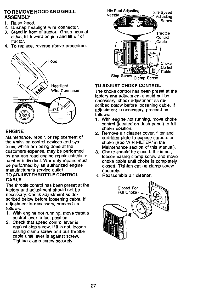
TO REMOVE HOOD AND GRILL
ASSEMBLY
1. Raise hood.
2. Unsnap headlight wire connector.
3. Stand in front of tractor. Grasp hood at
sides, tilttoward engine and liftoff of
tractor.
4. To replace, reverse above procedure.
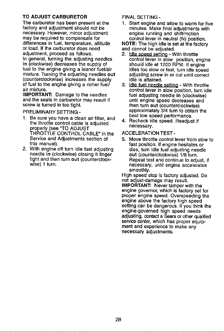
Idle Fuel Adjusting idle Speed
Needle Adjusting
Screw
Throttle
Control
Cable
Headlight
Wire Connector
ENGINE
Maintenance, repair,or replacement of
the emission control devices and sys-
tems, which are being done at the
customers expense, may be performed
by any non-road engine repair establish-
ment or individual. Warranty repairs must
be performed by an authorized engine
manufacturer'sservice outlet.
TO ADJUST THRO'R'LE CONTROL
CABLE
The throttlecontrolhas been preset at the
factory and adjustment should not be
necessary.Check adjustmentas de-
scribedbelow before looseningcable. If
adjustmentis necessary, proceed as
follows:
1. With engine not running, move throttle
control lever to fast position.
2. Check that speed control lever is
against stop screw. If it is not, loosen
casing clamp screw and pull throttle
cable until lever is against screw.
Tighten clamp screw securely.
Stop Screw
TO ADJUST CHOKE CONTROL
The choke control has been preset at the
factory and adjustment should not be
necessary, check adjustment as de-
scribed below before loosening cable. If
adjustment is necessary, proceed as
follows:
1. With engine not running, move choke
control (located on dash panel) to full
choke position.
2. Remove air cleaner cover, filter and
cartridge plate to expose carburetor
choke (See "AIR FILTER" in the
Maintenance section of this manual).
3. Choke should be closed. If it is not,
loosen casing clamp screw and move
choke cable until choke is completely
closed. Tighten casing clamp screw
securely.
4. Reassemble air cleaner.
Closed For
Full
27
TO ADJUST CARBURETOR
The carburetorhas been present at the
factory and adjustment should not be
necessary. However, minor adjustment
may be requiredto compensate for
differences in fuel, temperature, altitude
or load. If the carburetor does need
adjustment, proceed as follows:
In general, turning the adjusting needles
in (clockwise) decreases the supply of
fuel to the engine giving a leaner fuel/air
mixture. Turning the adjusting needles out
(counterclockwise) increases the supply
of fuel to the engine giving a richer fuel/
air mixture.
IMPORTANT: Damage to the needles
and the seats in carburetor may result if
screw is turned in too tight.
PRELIMINARY SETTING -
1. Be sure you have a clean air filter, and
the throttle control cable is adjusted
properly (see "TO ADJUST
THRO'N'LE CONTROL CABLE" in the
Service and Adjustments section of
this manual).
2. With engine off turn idle fuel adjusting
needle in (clockwise) closing it finger
tight and then turn out (counterclock-
wise) 1 turn.
FINAL SETFING -
1. Start engine and allow towarm forfive
minutes. Make final adjustmentswith
engine running and shift/motion
control lever in neutral (N) position.
NOTE: The high idle is set at the factory
and cannot be adjusted.
2. Idle shoed settina - With throttle
control lever in slow position, engine
should idle at 1200 RPM. If engine
idles too slow or fast, turn idle speed
adjusting screw in or out until correct
idle is attained.
3. Idle fuel needle setting • With throttle
controllever in slowposition, turn idle
fuel adjusting needle in (clockwise)
untilengine speed decreases and
then turn out (counterclockwise)
approximately3/4 turn to obtain the
best low speed performance.
4. Recheck idle speed. Readjust if
necessary.
ACCELERATION TEST-
5. Move throttle control lever from slow to
fast position. If engine hesitates or
dies, turn idle fuel adjusting needle
out (counterclockwise) 1/8 turn.
Repeat test and continue to adjust, if
necessary, until engine accelerates
smoothly.
High speed step isfactory adjusted. Do
notadjust-damage may result.
_MPORTANT: Never tamper withthe
engine governor, whichis factory setfor
proper engine speed. Overspeeding the
engine above the factory highspeed
setting can be dangerous. Ifyou thinkthe
engine-governed high speed needs
adjusting, Contacta Searsorotherqualified
servicecenter,which has proper equip-
ment and experience to make any
necessary adjustments.
28
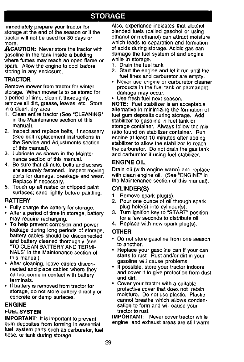
Immediatelyprepare your tractorfor
storage at the end of the season or if the
tractor will not be used for 30 days or
more.
_,CAUTION: Never store the tractor with
gasoline in the tank inside a building
where fumes may reach an open flame or
spark. Allow the engine to cool before
storing in any enclosure.
TRACTOR
Remove mower from tractor for winter
storage. When mower is to be stored for
a period of time, clean it thoroughly,
remove ell dirt, grease, leaves, etc. Store
in a clean, dry area.
1. Clean entire tractor(See "CLEANING"
in the Maintenance section of this
manual).
2. Inspect and replace belts, if necessary
(See belt replacement instructions in
the Service and Adjustments section
of this manual).
3. Lubricate as shown in the Mainte-
nance section of this manual
4. Be sure that all nuts, bolts and screws
are securelyfastened. Inspect moving
parts for damage, breakage and wear.
Replace if necessary.
5. Touch up all rusted or chipped paint
surfaces; sand lightly before painting.
BATTERY
• Fully charge the battery for storage.
• After a period of time in storage, battery
may require recharging.
• To help prevent corrosionand power
leakage during long periods of storage,
battery cables should be disconnected
and battery cleaned thoroughly (see
"TO CLEAN BATTERY AND TERMI-
NALS" in the Maintenance section ol
this manual).
• After cleaning, leave cables discon-
nected and place cables where they
cannot come in contactwith battery
terminals.
• If battery is removed from tractor for
storage, do not store battery directly on
concrete or damp sudaces.
ENGINE
FUEL SYSTEM
IMPORTANT: Itis important toprevent
gum deposites from forming in essential
fuel systemparts suchas carburetor,fuel
hose, or tank duringstorage.
Also, expedance indicates that alcohol
blended fuels (called gasohol or using
ethanol or methanol) san attract moisture
which leads to separation and formation
of acids during storage. Acidic gas can
damage the fuel system of and engine
while in storage.
1. Drain the fuel tank.
2. Start the engine and let it run until the
fuel lines and carburetor ere empty.
• Never use engine or carburetor cleaner
products in the fuel tank or permanent
damage may occur.
• Use fresh fuel next season.
NOTE: Fuel stabilizer is an acceptable
alternative in minimizing the formation of
fuel gum depositsduring storage. Add
stabilizer to gasoline in fuel tank or
storage container. Always follow the mix
ratio found on stabilizer container. Run
engine at least 10 minutes after adding
stabilizer to allow the stabilizer to reach
the carburetor. Do not drain the gas tank
and carburetor if using fuel stabilizer.
ENGINE OIL
Drain oil (with engine warm) and replace
with clean engine oil. (See "ENGINE" in
the Maintenance section of this manual).
CYLINDER(S)
1. Remove spark plug(s).
2. Pour one ounce of oil through spark
plug hole{s) into cylinder(s).
3. Turn ignition key to "START" position
for a few seconds to distribute oil.
4. Replace with new spark plug(s).
OTHER
• Do not store gasoline from one season
to another.
• Replace your gasoline can if your can
starts torust. Rust and/or ditt in your
gasoline will cause problems.
• If possible,store your tractorindoors
and cover itto give protectionfrom dust
and dirt.
• Cover your tractorwith a suitable
protectivecover that does not retain
moisture, Do not use plastic. Plastic
cannot breathe which allows conden-
sation to form and willcause your
tractorto rust.
IMPORTANT: Never cover tractor while
engine and exhaust areas are stilt warm.
29

TROUBLESHOOTING CHART
=ROBLEM CAUSE CORRECTION
Will not start
Hard to start
Enginewill not
turn over
Engine clicks but
will not start
I1. Out of fuel.
2. Engine not "CHOKED"
properly.
3. Engine flooded.
4. Bad spark plug.
5. Dirty air filter.
6. Dirty fuel filter.
7 Water in fuel.
8. Loose or damaged wiring.
9. Carburetor out ofadjustment.
10.Engine valves out of
adjustment.
1. Dirty air filter.
2. Bad spark plug.
3. Weak or dead battery.
4. Dirty fuel filter.
5. Stale or dirty fuel.
6. Loose or damaged wiring.
7. Carburetor out of adjustment.
8. Engine valves out of
adjustment.
1. Clutch/brake pedal not
depressed.
2. Attachment clutch is
engaged.
3. Weak or dead battery.
4. Blown fuse.
5. Corroded battery terminals.
6. Loose or damaged wiring.
7. Faulty ignition switch.
8. Faulty solenoid or starter.
9. Faulty operator presence
swithch(es).
1. Weak or dead battery.
2. Corroded battery terminals.
3. Loose or damaged wiring.
4. Faulty solenoid or starter.
1. Fill fuel tank.
2. See "1"OSTART ENGIN E"
in Operation section.
3. Wait several minutes
before attempting to start.
4. Replace spark plug.
5. Clean/replace air filter.
6. Replace fuel filter.
7. Drain fuel tank and
carburetor, refill tank with
fresh gasoline and replace
fuel filter.
8. Check all wiring.
9. See "To Adjust Carburetor"
in Service Adjustments
section.
1O.Contact a Sears or other
qualified service center.
1. Clean/replace air filter.
2. Replace spark plug.
3. Recharge or replace
battery.
4. Replace fuel filter.
5. Drain fuel tank and refill
with fresh gasoline.
6. Check all wiring.
7. See "To Adjust Carburetor"
in Service Adjustments
section.
8. Contact a Sears or other
qualified service center..
1. Depress clutch/brake
pedal.
2. Disengage attachment
clutch.
3. Recharge or replace
battery.
4. Replace fuse.
5. Clean battery terminals.
6. Check all wiring.
7. Check/replace ignition
switch.
8. Check/replace solenoid or
starter.
9. Contact a Sears or other
qualified service center.
1. Recharge or replace battery.
2. Clean battery terminals.
3. Check all wiring.
4. Check/replace solenoid or
starter.
3O
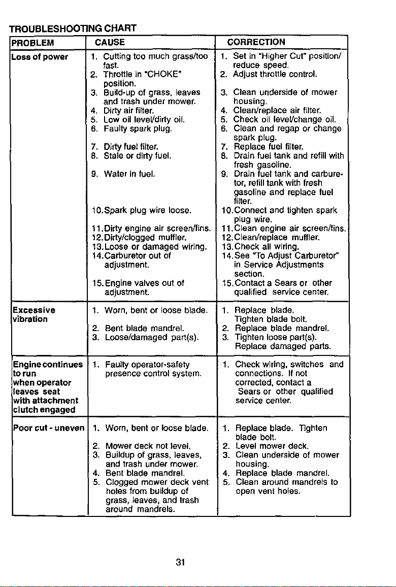
TROUBLESHOOTING CHART
_'ROBLEM CAUSE CORRECTION
.oss of power 1. Cutting too much grass/too
Excessive
vibration
fast.
2. Throttlein "CHOKE"
position,
3. Build-up of grass, leaves
and trash under mower.
4, Dirty air filter.
5. Low oil leveVdirty oil.
6. Faulty spark plug.
Enginecontinues
torun
when operator
leaves seat
with attachment
clutch engaged
Poorcut-uneven
7, Dirty fuel fUter.
8. Stale or dirty fuel.
9. Water in fuel.
10.Spark plug wire loose.
11.Dirty engine air screen/fins.
12,Dirty/clogged muffler.
13.Loose or damaged wiring.
14,Carburetor out of
adjustment.
15.Engine valves out of
adjustment.
1. Worn, bent or loose blade.
2. Bent blade mandrel.
3. Loose/damaged part(s).
1. Faultyoperator-safety
presence controlsystem.
1. Worn, bent or loose blade.
2. Mower deck not level.
3. Buildupof grass, leaves,
and trash under mower.
4. Bent blade mandrel.
5. Clogged mower deck vent
holes from buildupof
grass, leaves, and trash
around mandrels.
1, Set in =Higher Cut" position/
reduce speed.
2. Adjust throttle control.
3. Clean underside of mower
housing.
4. Clean/replace air filter,
5. Check oil level/change oil.
6. Clean and regap or change
spark plug.
7. Replace fuel filter.
8. Drain fuel tank and refill with
fresh gasoline.
9. Drain fuel tank and carbure-
tor, refill tank with fresh
gasoline and replace fuel
filter.
10.Connect and tighten spark
plug wire.
11.Clean engine air screen/fins.
12.Clean/replace muffler.
13.Check all wiring.
14.See "To Adjust Carburetor"
in Service Adjustments
section,
15,Contact a Sears or other
qualified service center.
1. Replace blade,
Tighten blade bolt.
2, Replace blade mandrel.
3. Tighten loose part(s).
Replace damaged pads.
1. Check wiring,switches and
connections. If not
corrected, contact a
Sears or other qualified
service center.
1. Replace blade. "13ghten
blade bolt.
2. Level mower deck,
3. Clean underside of mower
housing.
4. Replace blade mandrel.
5. Clean around mandrels to
open vent holes,
31
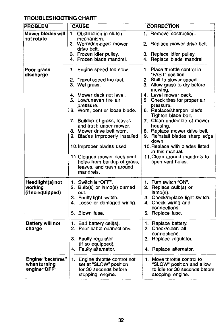
TROUBLESHOOTING CHART
PROBLEM CAUSE CORRECTION
Mower blades will 1. Obstruction in clutch 1. Remove obstruction,
not rotate mechanism.
2. Worn/damaged mower 2. Replace mower drive belt.
drive belt.
3. Frozen idler pulley• 3. Replace idler pulley.
4. Frozen blade mandrel. 4. Replace blade mandrel.
iPoor grass 1. Engine speed too slow.
discharge
Headlight(s) not
working
(if so equipped)
2. Travel speed too fast.
3. Wet grass.
4. Mower deck not level.
5. Low/uneven tire air
pressure.
6. Worn, bent or loose blade.
7. Buildup of grass, leaves
and trash under mower.
8. Mower drive belt worn.
9. Blades improperly installed.
10.Improper blades used•
11.Clogged mower deck vent
holes from buildup of grass,
leaves, and trash around
mandrels.
1. Switch is"OFF".
2. Bulb(s) or lamp(s) burned
out.
3. Faulty light switch.
4. Loose or damaged wiring.
1. Place throttlecontrol in
=FAST"position,
2. Shift to slower speed•
3. Allow grassto drybefore
mowing•
. Level mower deck.
• Check tiresfor proper air
pressure•
6. Replace/sharpen blade.
Tighten blade bolt.
7. Clean underside of mower
housing•
8, Replace mower drive belt•
9. Reinstall brades sharp edge I
down. I
10.Replace with blades listed
n ths manua,
11.Clean around mandrels to
open vent holes.
1. Turn switch"ON".
2. Replace bulb(s) or
lamp(s).
3. Check/replace light switch.
4. Check wiring and
connections.
5. Replace fuse.
5. Blown fuse.
Battery will not 1. Bad battery cell(s), 1. Replace battery,
charge 2, Poor cable connections. 2, Check/clean all
connections,
3. Faulty regulator 3. Replace regulator.
(if so equipped)•
4. Faulty a]ternator. 4. Replace alternator.
Engine"backfires" 1, Engine throttle controlnot I 1. Move throttle controlto
when turning sat at "SLOW" position "SLOW" positionand allow
engine"OFF' for 30 seconds before to idle for 30 secondsbefore t
i stopping engine• stopping engine. I
32
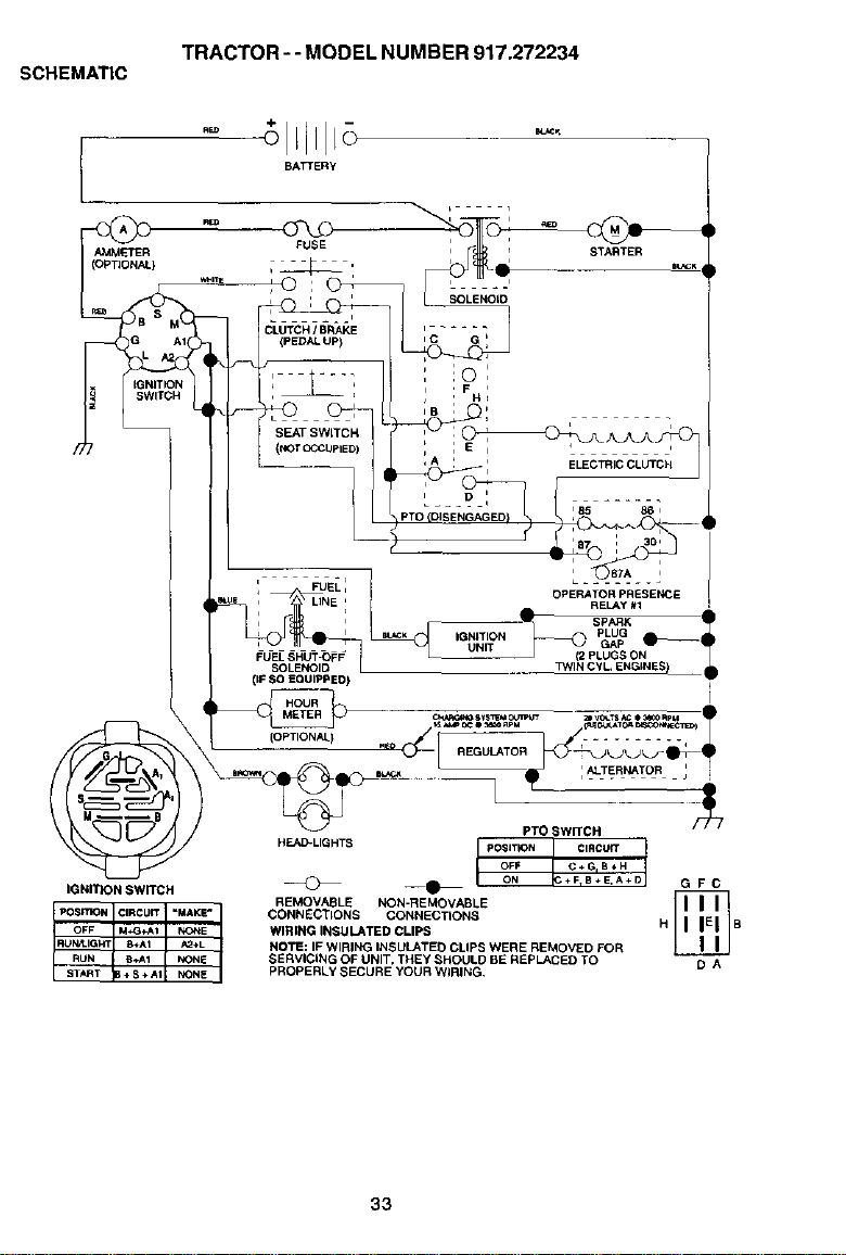
SCHEMATIC
TRACTOR-- MODEL NUMBER 917.272234
AMMETER
(OPTIONAL}
IGNITI )N _
IGNITION SWITCH
BATTERy
PTO SWITCH
HEAD-LIGHTS POSmON L CIRCU_IoFF C+G,B.H
@ ___ ON ÷F_B÷E,A+D G F C
REMOVABLE NON-REMOVABLE
CONNECTIONS CONNECTIONS
WIRING INSULATED CLIPS H B
NOTE: IF WIRING INSULATED CLIPS WERE REMOVED FOR
SERVICING OF UNIT, THEY SHOULD BE REPLACED TO D A
PROPERLY SECURE YOUR WIRING.
33
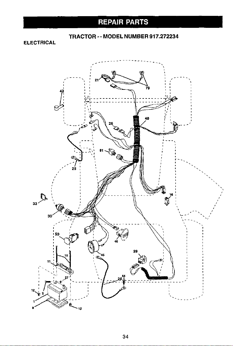
ELECTRICAL
TRACTOR -- MODEL NUMBER 917.272234
43
79
4O
29
34
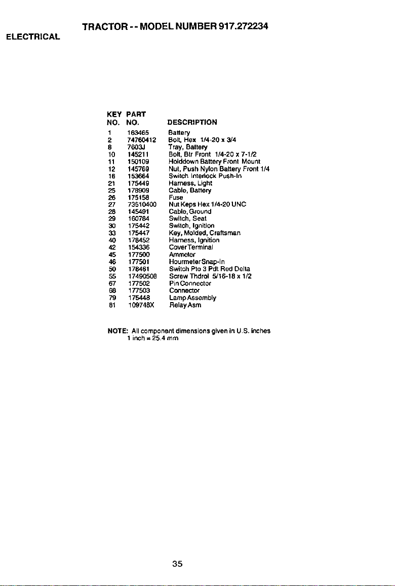
ELECTRICAL
TRACTOR -- MODEL NUMBER 917.272234
KEY PART
NO. NO. DESCRIPTION
1 163465 Battery
2 74760412 Bolt, Hex 1/4-20 x 3/4
8 7603,1 Tray, Battery
10 145211 Bolt, Btr Front 1/4-20 x 7-1/2
11 150109 Holddown Battery Front Mount
12 145769 Nut, Push Nylon Battery Front 1/4
16 153664 SwitCh Intedock Push-In
21 175449 Harness, Light
25 178909 Cable, Battery
26 175158 Fuse
27 73510400 Nut Keps Hex 1/4-20 UNC
28 145491 Cable, Ground
29 160784 Switch, Seat
30 175442 Switch, Ignition
33 175447 Key, Molded, Craftsman
40 178452 Harness, Ignition
42 154336 CoverTerminal
45 177500 Ammeter
46 177501 Hourmetar Snap-In
50 178461 Switch Pro3 Pdt Red Delta
55 17490508 Screw Thdrol 5v'16-18 x 1/2
67 177502 Pin Connector
68 177503 Connector
79 175448 Lamp Assembly
81 109748X RelayAsm
NOTE: All component dimensions given in U.S. inches
1 inch = 25.4 mm
35
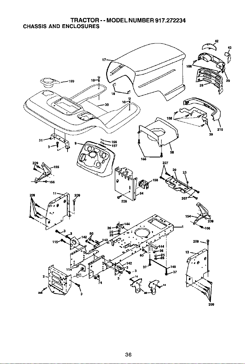
TRACTOR - - MODEL NUM BER 917,272234
CHASSIS AND ENCLOSURES
42
3 142 60 26
2O9
29
36
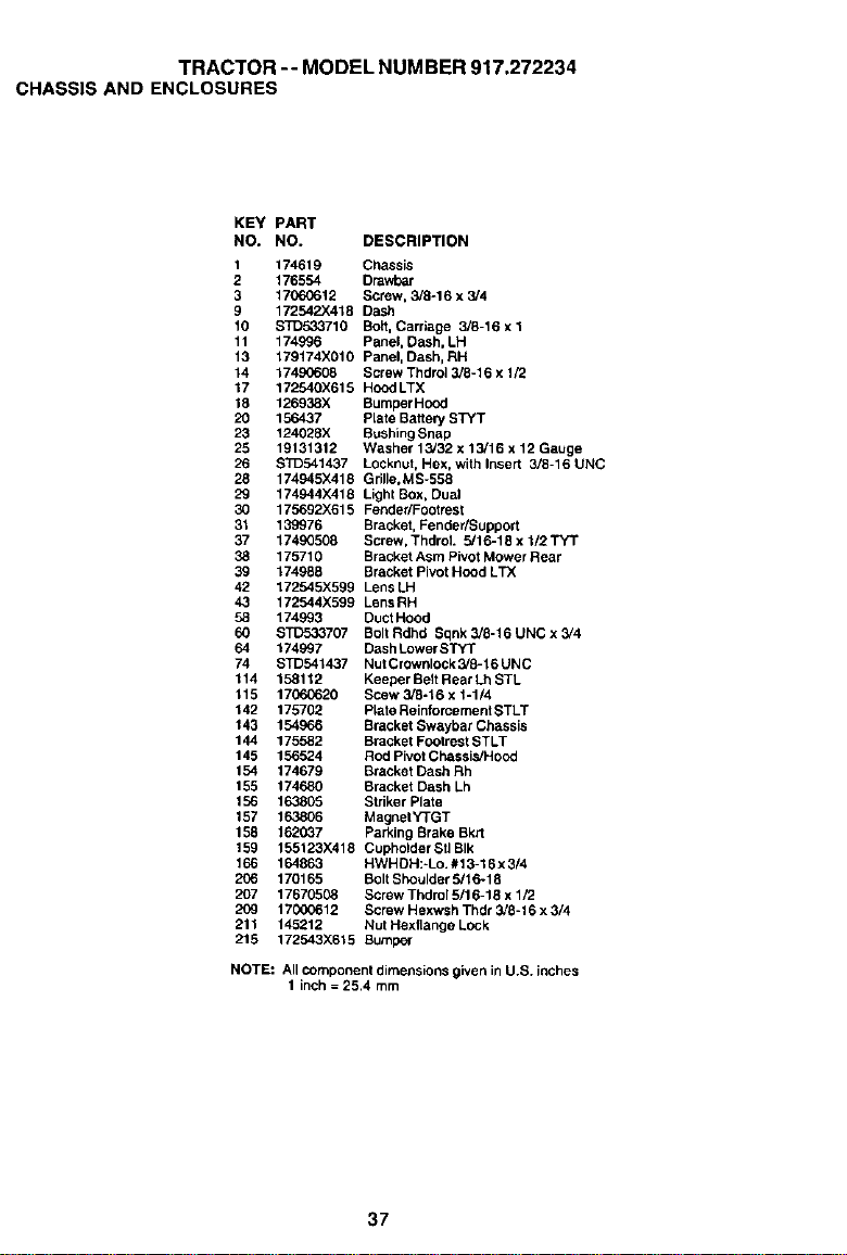
TRACTOR-- MODEL NUMBER 917.272234
CHASSIS AND ENCLOSURES
KEY PART
NO, NO. DESCRIPTION
1 174619 Chassis
2 176554 Drawbar
3 17060612 Screw, 3/8o16 x 3/4
9 172542X418 Dash
10 $3"D533710 Bolt, Carriage 3/8-16 x 1
11 174996 Panel, Dash, LH
13 179174X010 Panel, Dash, RH
14 17490608 Screw Thdrol 3/8-16 x 1/2
17 172540X615 Hood LTX
18 126938X Bumper Hood
20 156437 Prate Battery STYT
23 124028X BushingSnap
25 19131312 Washer 13/32 x 13/16 x 12 Gauge
26 STD541437 Locknut, Hex, with Insert 3/8-16 UNC
28 174945X418 Grille,MSv558
29 174944)(418 Light Box, Dual
30 175692X615 FendedFootrest
31 139976 Bracket, FendedSupport
37 17490508 Screw. Thdrot 5/16-18 x 1/2 TYT
38 175710 BracketAsm Pivot Mower Rear
39 174988 Bracket Pivot Hood LTX
42 172545X599 LensLH
43 172544X599 LensRH
58 174993 DuctHood
60 STD533707 BoltRdhd Sqnk3/8-16UNCx3/4
64 174997 Dash LowerSTYT
74 STD541437 Nul Crownlock 3/8-16 UNC
114 158112 Keeper BeltRear Lh STL
115 17060620 Scew 3/8-16 x I-1/4
142 175702 Plate Reinforcement STLT
143 154966 Bracket Swaybar Chassis
144 175582 Bracket Footrest STLT
145 156524 Rod PivotChassis/Hood
154 174679 Bracket Dash Rh
155 174680 Bracket Dash Lh
156 163805 Striker Plate
157 163806 MagnetYTGT
158 162037 Parking Brake Bkrt
159 155123X418 CupholderStlBIk
166 164863 HWHDH:*Lo.#13-16x 3/4
206 170165 Bolt Shoulder 5/16-18
207 17670508 Screw Thdrol 5/16-18 x 1/2
209 17000612 Screw Hexwsh Thdr 3/8-16 x 3/4
211 145212 Nut Hexflange Lock
215 172543X615 Bumper
NOTE: All component dimensions given in U.S. inches
1 inch = 25.4 mm
37
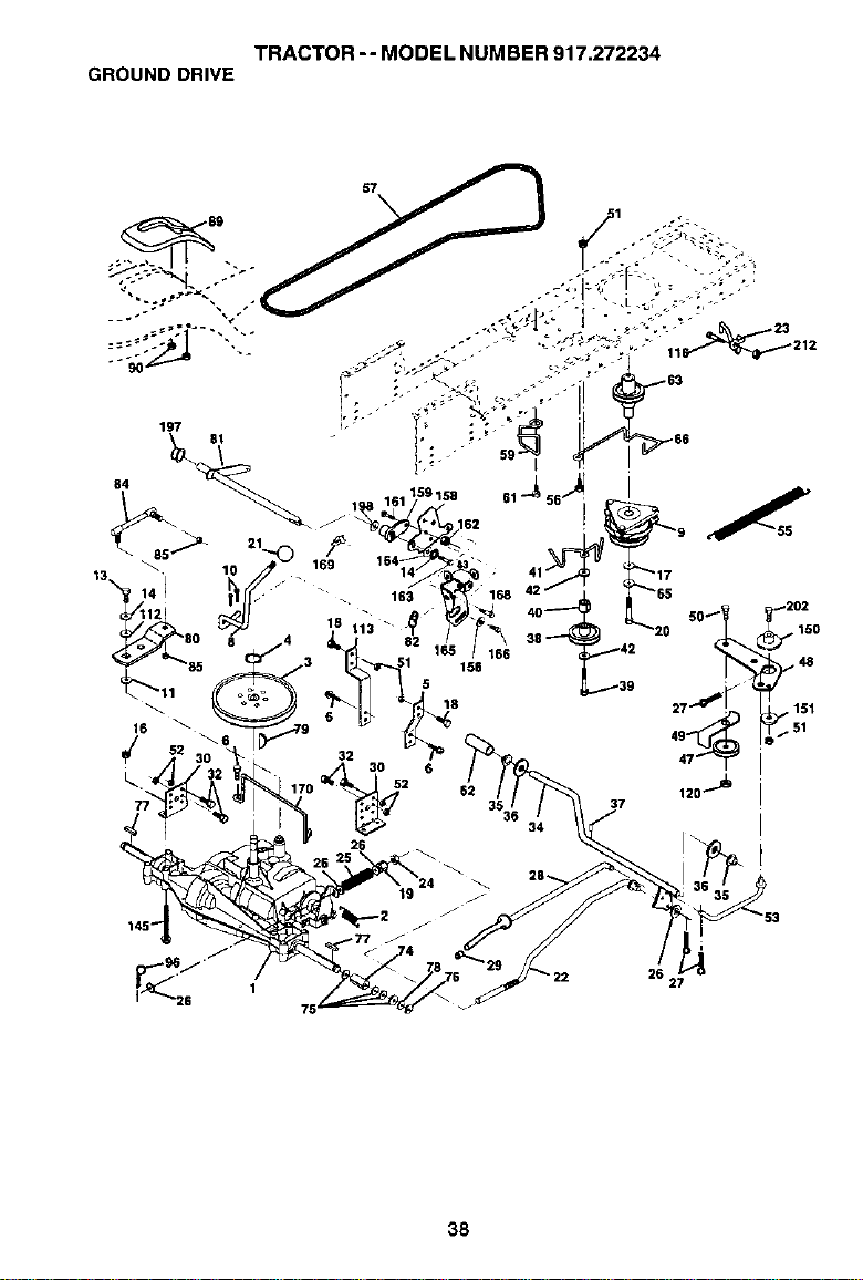
TRACTOR -- MODEL NUM BER 917.272234
GROUND DRIVE
26 27
38
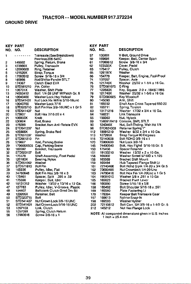
TRACTOR-- MODEL NUMBER 917.272234
GROUND DRIVE
KEY PART KEY PART
NO, NO. DESCRIPTION NO. NO, DESCRIPTION
t ........ T_ansaxle (See Breakdown) 57 130801 V-Belt, Ground Drive
Peerless 206-545C 59 169691 Keeper, Belt, Center Span
Spring, Return, Brake 61 17060612 Screw 3/8-16 x 3/4
Pulley, Transaxle 62 123533X Cover, Pedal
Ring,Retainer 63 175417 Pulley, Clutch
Strap,Torque 65 126197X Washer
Screw 5/16-18 x 3/4 66 154778 Keepor, Belt, Engine, Fool-Proof
Rod Shifter Fender STLT 74 137057 Spacer, Axle
Clutch Elect EVX 75 121749X Washer 25/32 x 1-1/4 x 16 Ga.
Pin, Cotter 76 STD581075 E-Ring
Washer, Shift plate 77 123583X Key, Square 2,0 x ,1845/.1565
Bolt 1/4-28 UNF W/Patch Gr. 8 78 121748X Washer 25/32 x 1-5/8 x t6 Ga
Washer Lock Hvy Helical 79 STD580025 Key Woodruff
Nut Lock Hx W/tns 6/16-18uric 80 145090 Arm, Shift
Washer Lock 7/16 81 165592 Shaft Asm Cross Tapered 650 20
Bolt Fin Hex 3/8-16UNC x 1 Gr 5 53 165711 Spring, Torsion
Nut 83 19171216 Washer 17/39 x 3/4 x 16 Ga,
Bolt Hex 7116-20 x 4 84 166231 LinkTransaxle
Kt'.ob 85 15O_60 Nut, Nylock
Rod, Brake 89 158391X419 Console. Shift, STLT
BracketAsm Anti=Rotate EVX 90 124346X Nut, SelfoThding,Wsh Hd 1/4
Nut 96 $3_624003 Retainer Spring 1"
Spring, BrakeRod 112 19091210 Washer 9/32x3/4xlOGa.
Washer 113 127285X Strap Torque 90 Degrees
Pin 116 72140608 BoltRDHD 3/8-16 x 1
ROd,Parking Brake 120 73900600 Nut Lock 3/9-16
Cap, Parking Brake 145 74490540 Bolt, Hex Flghd 5/16-18 Gr. 5
Bracket, Transaxle 150 175456 SpacerRetainer
B01t 151 19133210 Washer 15/32 x 2 x tO Ga.
Shaft Assembly, Foot Pedal 156 166002 Washer Breed 5/161D x 1,125
Beaodg, Nylon 158 165559 Bracket Shift Mount
Washer 159 165494 Hub Tapered Flange ShiftLt
Roll Pin 161 72140406 BoltRdhd Sqnk 1/4-20 x 5/4 Gr.5
Pulley, Idler, Flat 162 73680400 NutCrownlocklt4-20Uno
Belt Fin Hex 3/8-16 x 3 163 74780416 BoltHex Fin 1/4-20Uric x 1 Gr 5
Spacer, Split .395 x .59 164 19091010 Washer 5/8 x .281 x 10 Ga
Keeper, Belt, Idler 165 165623 Bracket Pivot Lever
Washer 13/32x13/16x12Ga, 166 166880 Sc_ew5/16-18x518
Pulley, Idler, V-Groove, Plasso 168 165492 Bolt Shoulder 5/16-18 x .561
Bellcrank Clutch Grod Dry Stl 169 165580 Plate Fastening Lt
Retainer, Belt 170 178394 Keeper BeltTransaxle Gear
Bolt 197 169613 NylinerSnapIn
Nut Crown Lock 3/8-16 UNC 198 169593 Washer Nyliner
Nut Crown Lock 5/16-18 UNC 202 72110612 Bolt Carr. SH 3/8-16 x 1-1/2 Gr. 5
Link, Clutch 212 145212 Nut Hex Flange Lock
Spring, Clutch Return
Screw 3/5-16 x 1 NOTE: All component dimensions given in U.S. inches
1 inch = 25.4 mm
2 146682
3 1235O6X
4 12OOOO28
5 121520X
6 17060512
8 165866
9 174367
10 STO561210
11 105701X
13 74_12
14 10040400
16 STD541431
17 16040700
18 STD523710
19 BTD541437
20 173937
21 106933X
22 13O804
23 178289
24 STD541237
25 106888X
26 STD551037
27 BTD561210
28 179607
29 1795O8X505
30 169592
32 STD523107
34 175578
35 120183X
36 STD551053
37 STD571810
38 165936
39 74760648
40 t 75461
41 175556
42 19131312
47 127783
48 154407
49 123205X
5O S'_523715
51 STD541437
52 STD541431
53 105710X
55 105709X
56 17060616
39
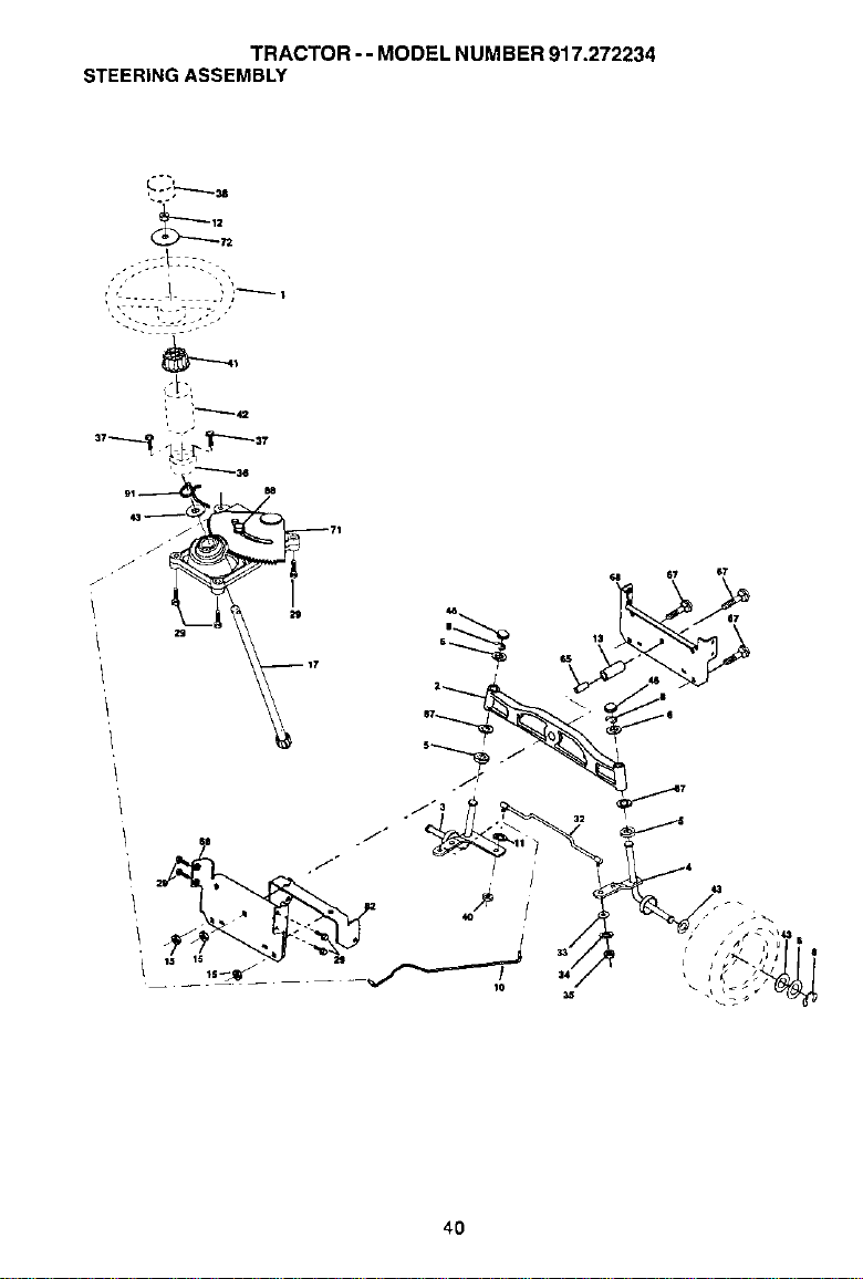
TRACTOR -- MODEL NUMBER 917.272234
STEERINGASSEMBLY
,Lo._____
72
', , ---n..= 22- ,
'.?-:::)...::::.."
4O

TRACTOR - - MODEL NUMBER 917.272234
STEERINGASSEMBLY
KEY PART
NO. NO. DESCRIPTION
1
2
3
4
5
6
8
10
11
12
13
15
17
29
32
33
34
35
36
37
38
4O
41
42
43
46
65
67
68
71
72
82
87
88
91
175139X418 Steenng Wheel
172393 Axle Assembly Cast Iron
169840 Spindle Assembly, LH.
169839 Spindle Assembly, R.H,
6266H Bearing, Race, Thrust, Hardened
121748X Washer 25/32 x 1-5/8 x 16 Gauge
12000029 Ring, Klip
175121 Draglink
10040600 Washer Lock 3/8
73940800 Nut Hex Jam Toplock 1/2-20 Unf
136518 Spacer Brg Axle Front
145212 Nut Hexflange Lock
177883 Shaft Assembly. Steering
17060612 Screw, 3/8-16 x 5/4
170162 Rod,Tie
19111216 Washar 11/92 x 3/4 x 16 Ga/
STD551131 Washer Lock Hvy Spt. 5/16
73540500 Locknut5/16-24 Unf
159105 Bushing, Steering
152927 Screw
17514OX418 Insert, SteeringWheel
STD541537 Gripco Nut
159945 Adaptor, SteeringWheel
174530X418 Boot, Steering Shaft
121749X Washer 25/32 x 1-1/4 x 16 Gauge
121232X Cap, Spindle
160367 Spacer Brace AXle
72140618 So9 Bdhd Sq 5/8-16 UNC x 2-1/4
169827 Axle. Brace
175146 SteeringAsm.
19182411 Washer 9/16 Idx 1-1/2Od 11 G Zin
169835 Bracket Susp Chassis Front
173966 Washer Flat .791 x 1 1/2 x .14
175118 BoltShoulder 7/16-20
175553 ClipSteering
NOTE: All component dimensions given in UIS. inches
1 inch = 25,4 mm
41
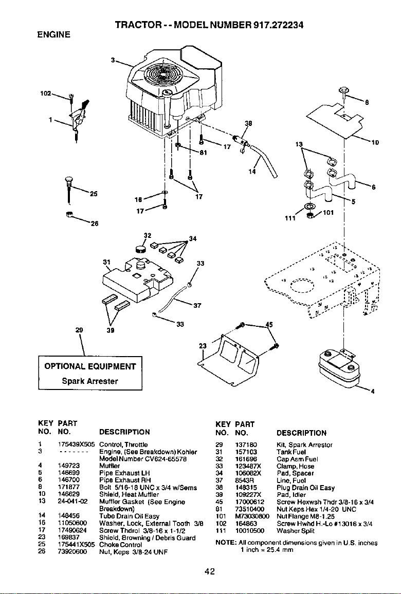
ENGINE
TRACTOR -- MODEL NUMBER 917,272234
i
A
17
29 39
\
OPTIONAL EQUIPMENT
Spark Arrester
KEY PART
NO. NO. DESCRIPTION
1 175439X505 Control, Throttle
3 ....... Engine, (See Breakdown) Kohler
Model Number CV624-65578
4 149723 Muffler
5 146699 Pipe Exhaust LH
6 146700 Pipe Exhaust RH
8 171877 Bolt 5/16-18 UNC x 3/4 w/Seres
10 146629 Shield, Heat Muffler
13 24-041-02 Muffler Gasket (See Engine
Breakdown)
14 148456 Tube Drain Oil Easy
16 11050600 Washer. Lock, External Tooth 3/8
17 17490624 ScrewThdrol 3/8-16 x 1-1/2
23 169837 Shield, Brownleg /Debris Guard
25 175441X505 Choke Control
26 73920600 Nut, Keps 3/8-24 UNF
KEY PART
NO. NO, DESCRIPTION
29 137180 Kit, Spark An'ester
31 157103 Tank Fuel
3_ 161696 CapAsmFuel
33 123487X Clamp, Hose
34 106082X Pad, Spacer
37 8543R Line, Fuel
38 148315 Plug Drain Oil Easy
39 109227X Pad, Idler
45 170(_612 Screw Hexwsh Thdr 3/8-16 x 3/4
81 73510400 Nut Keps Hex 1/4-20 UNC
101 M73030800 Nut Flange M8-1,25
102 164863 Screw Hwhd H -LO #13016 x 3/4
111 10010500 Washer Split
NOTE: All component dimensions g}ven in U S inches
1 inch = 25.4 mm
42
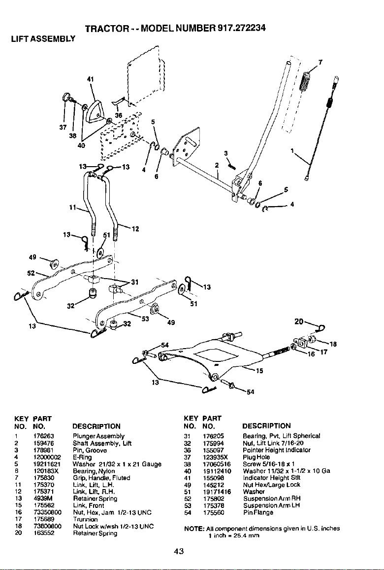
LIFT ASSEMBLY
37
36
4O
TRACTOR-- MODEL NUMBER 917.272234
° h
5
6
6
51
49
KEY PART
NO. NO.
1 176263
2 159476
3 178981
4 120CO002
5 19211621
6 120183X
7 17583O
11 175379
12 175371
13 493_M
15 175562
16 73350800
17 175689
18 73800800
20 163552
DESCRIPTION
Plunger Assembly
Shaft Assembly, Lift
Pin, Groove
E-Ring
Washer 21/32 x 1 x 21 Gauge
Bearing,Nylon
Grip, Handle, Fluted
Link, Lift, L.H,
Link, Lift, R,H,
RetainerSpring
Link,Front
Nut, Hex, Jam 1/2-13 UNC
Tturglk_n
NutLock whvsh 1/2-13 UNC
RetainerSpring
KEY PART
NO. NO. DESCRIPTION
31 176205 Bearing, Pvt. Lift Spherical
32 175994 Nut, Lift Link 7/16-20
36 155097 PointerHeight Indicator
37 123935X PlugHole
38 17060516 Screw 5/16-18 x 1
40 19112410 Washer 11132 x 1-1/2 x 10 Oa
41 155098 IndiCatorHeight Stlt
49 145212 Nut Hex/Large Lock
51 19171416 Washer
52 175802 Suspension ArmRH
53 175378 Suspension ArmLH
54 175560 PinFlange
NOTE: All component dimensions given in U.S. inches
1 inch = 25.4 rnm
43
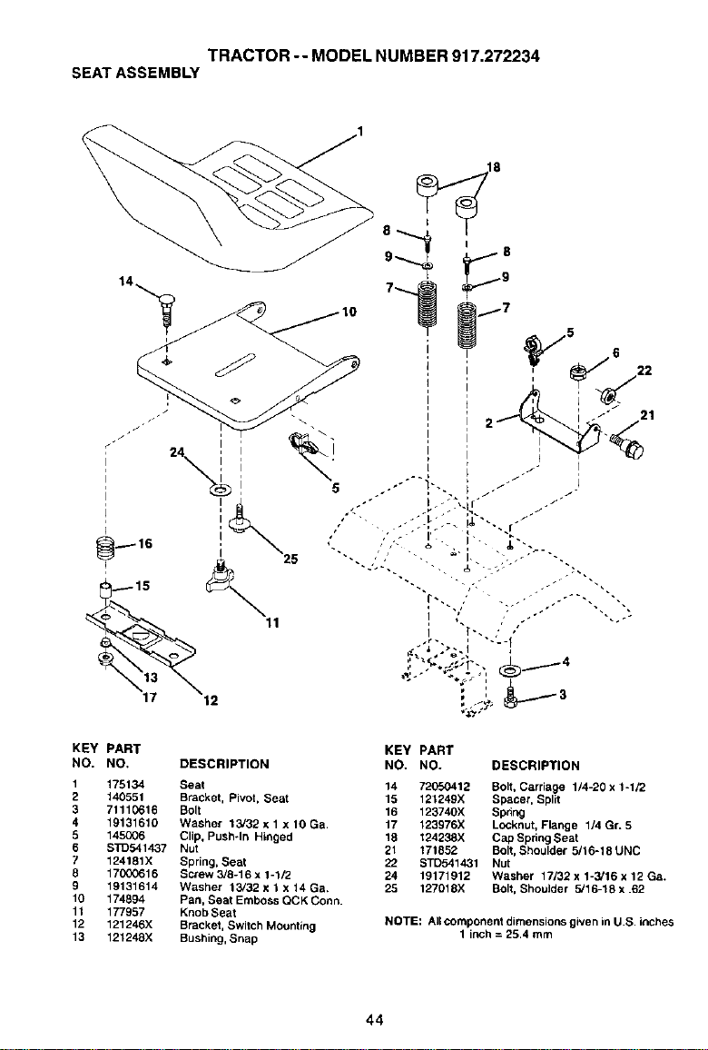
TRACTOR-- MODEL NUMBER 917.272234
SEAT ASSEMBLY
I 25
11
12
KEY PART
NO. NO. DESCRIPTION
1 175134 Seat
2 140551 Bracket, Pivot, Seat
3 71110616 Bolt
4 19131610 Washer 13/32 x 1 x 10 Ga,
5 145006 Clip, Push÷In Hinged
6 STD541437 Nut
7 124181X Spring, Seat
8 17000616 Screw 3/8-16 x 1-1/2
9 19131614 Washer 13/32 x 1 x 14 Ga,
10 174894 Pan, Seat Emboss QCK Conn.
1t 177957 Knob Seat
12 121246)( Bracket, Switch Mounting
13 121248X Bushing, Snap
KEY PART
NO. NO. DESCRIPTION
14 72050412 Bolt, Carriage 1/4-20 x 1-1/2
15 121249X Spacer, Split
16 123740X Spring
17 123976X Locknut, Flange 1/4 Gr. 5
18 124238X Cap Spbng Seat
21 171852 Bolt, Shoulder 9/16-18 UNC
22 BTD54143t Nut
24 19171912 Washer 17/32 x 1-3/16 x 12 Ga+
25 127018X Bolt, Shoulder 5/16-18 x .62
NOTE: Air component dimensions given in U.S. inches
1 inch = 29.4 mm
44
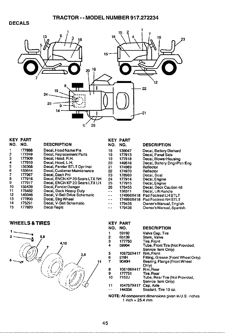
DECALS
13
TRACTOR - - MODEL NUMBER 917.272234
18
16
15
18
\
1
7
10
12
26
KEY PART
NO. NO.
1 177888
9 177249
3 177909
4 177910
5 156368
6 133644
7 177967
8 177916
9 177917
10 156439
11 178482
12 146046
13 177890
14 175291
15 177889
DESCRIPTION
Decal, Hood Name Pie.
Decal, Replacement Parts
Decal, Hood, R.H.
Decal, Hood, L.H.
Decal, Fender STLT Opr Inst
Decal, Customer Maintenance
Decal, Dash Pnl
Decal, ENCN KP20 Sears LTX RH
Decal, ENCN KP 20 Sears LTX LH
Decal, Fender Danger
Decal, Deck Heavy Duty
Decal, V-Belt Drive Schematic
Decal, StrgWheel
Decal, V-Belt Schematic
Decal Replc
KEY PART
NO. NO. DESCRIPTION
16 138047 Decal, Batter/Diehard
18 177913 Cecal, Panel Side
19 177918 Decal, BlowerHousing
20 149516 DecaJ,Batter/Dngr/Psn Eng
21 174969 Reflector
22 174970 Reflector
23 178989 Decal, Seat
24 177914 Decal, Engine
25 177915 Decal, Engine
26 178455 Decal, Deck Caution 48
- - 138311 Decal, LiltHandle
-- 174998)(418 Pad Fcotrest LH STLT
-- 174999X418 Pad Footrest RH STLT
-- 179435 Owner's Manual, English
-- 179436 Owner's Manual, Spanish
WHEELS &TIRES
5,8
4,10
11
KEY PART
NO. NO. DESCRIPTION
1 59192 Valve Cap, Tire
2 65139 Stem, Valve
3 177750 Tire, Front
4 59904 Tube, Front Tire (Not Provided,
Service 9era Only)
5 106732X417 Rim, Front
6 278H Fitting,Grease (FrontWheel Only)
7 9040H Beadng, Flange (Front Whee_
Only)
8 106108X417 Rim, Rear
9 177751 Tire, Rear
10 7152J Tube, Rear Tire (Not Provided,
Service Item Only)
11 104757X417 Cap, Axle
- - 144334 Sealant, Tire 10 oz.
NOTE: All component dimensions given in U.S inches
1 inch = 25,4 mm
45
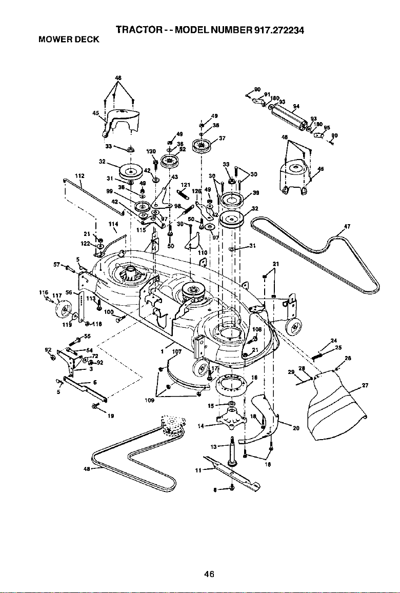
TRACTOR--MODELNUMBER917.272234
MOWERDECK
112
I
2t '
46
_90 91 80
i
11!
I
109
19
11_ 18
29 2 _
46
TRACTOR -- MODEL NUMBER 917.272234
MOWER DECK
KEY PART KEY PART
NO. NO. DESCRIPTION NO. NO. DESCRIPTION
1 174348 DeckWeldment Mower 48 55 72140608 Bolt 3/8-16 x 1
3 138017 Bracket Asm., Sway Bar 56 156986X431 Bar Pnt Adj,
5 4939M Retainer Spring 57 156941 PinHead Rivet
6 130832 Arm, Suspension, Rear(Sway Bar) 72 19131312 Washor 13/32 x 13/16 x 12
8 174365 Bott7/16 Asm. Blade 90 74760516 Bolt Hex 5/16-18 x 1
11 1739'20 Blade 91 178996 BracketAsm. Noseroller LH
13 174360 Shaft Asm. w/Lower Beadng 92 73800600 NutLock Hex W/Ins 3/6-16 Unc
14 174358 Asm Greasable,Mandrel 93 19171416 Washer 17/32 x 7/8
15 110485X Bearing, Bali,Mandrel 94 176066 Noserotler
16 174493 Stripper Mandrel Deck 95 175384 BracketAsm Noseroller RH
17 72110610 BoltRDHD Sq Neck 3/8-16xl.25 97 13.3943 Washer Hardened
18 72140505 BoB,Carriage 5/16-18 x 5/8 98 174370 SpringPrimary Drive
19 132827 Bolt, Hex Hd, Shoulder 5/16-18 99 175080 Pulley Idler'V"
20 174378 Baffle, Vortex Mower 100 72110616 Bolt RDHD Sqnk 3/6-16 UNC x 2
21 736805CO Nut, Crownlock 5/16-18 UNC 107 175294 Baffle Vac Edge Mower
24 105304X Cap, Sleeve 108 72110404 BoltCart.
25 178102 Spring, Torsion 109 73680400 NutCrownlock 1/4-20
26 110452X Nut, Push 110 175016 ArmSpring Secondary
27 174346X428 Deflector Shield 112 174387 LinkTension Relief Lever
28 19111016 Washer 11/32x5/8x16Ga, 113 72110508 BoltCarr, 5i16-18x1
29 131491 Rod,Hinge 114 174384 Tension Asm. Relief Lever
30 173984 Screw, Thdroll DOP. PT. Hex 115 174609 Ann Spdng Tension Relief
31 129963 Washer. Spacer Mower Vented 116 137644 Bolt, Shoulder
32 177865 Pulley,Mandrel 117 174873 GaugeWheel
33 178342 Nut, Fig. Top Lock Cntr. 9/16 119 73930600 Nut, Centerlock 3/8-16 UNC
36 19131316 Washer13/32x13/16x16Ga. 119 19121414 Washer 3/Sx7/Sx14Ga.
37 177968 Pulley, Idler 121 174371 SpringSecondary Drive
39 174375 Pulley, Idler, Driven 122 174606 Bushing PivotTension Relief
42 165723 Spacer, Retainer 126 174372 Arm, Idler, Primary Deck
43 174373 Arm, Idler Secondary 130 17060616 Screw 5/6-16 x 1.0
45 174343 Cover, Mandrel Deck 180 738005(;0 Nut LockHex W/Ins 5/16-18
46 137729 Screw, ThdroLI. 1/4-20 x 5/8 - - 175312 RoplacementMower, Complete
47 174369 V-Belt, Mower, Secondary - - 174356 Mandrel Asm. Service
48 174368 V-Belt, Mower, Primary (Includes Key Nos. 13-15)
49 73680600 Nut, Crownlock 3/6-16 UNC
50 72110612 Bolt, Carl 3/6-16 x 1-1/2 Gr, 5
52 175820 Pulley Idler Flat NOTE: All component dimensions given in U. S.
54 74780616 Bolt Fin Hex 5/8-16 x 1 inches 1 inch = 25.4 mm
47
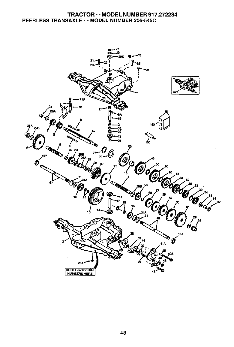
TRACTOR-- MODEL NUMBER 917.272234
PEERLESS TRANSAXLE - - MODEL NUMBER 206-545C
o --71B
47
157
48
TRACTOR - - MODEL NUMBER 917.272234
PEERLESSTRANSAXLE- - MODELNUMBER206-545C
KEY PART I<_=Y PART
NO. NO, DESCRIPTION NO. NO. DESCRIPTION
1 772147 Transaxle Cover 41A 790079 Brake Lever
2 780066A Needle Bearing 5/8" 42 792073A Screw 1/4 - 20 x 1-1/4"
3 770128 Transaxle Case 42A 792085,% Screw 1/4 - 20 x 2 1/4"
4 776395 Countershaft 43 792075 Locknut 5 / 16 - 24
5 776409 Output Shaft 44 79_Y25 Brake Pad Holder
6 778364 Spur Gear (38 teeth) 45 786066 Spacer .2625 x 1.0
6,% 778369 Spur Gear (15 teeth) 46 786086 Brake Lever Bracket
7 778330 Spur Gear (11 teeth) 47 774690 Axle (11-15 / 16" Long)
6 792180 Shift Key 48 774691 Axle (16 * 1 / 2" long)
8A 792047 Woodruff Key #9 49 778356 Spur Gear (29 teeth)
9 784352 Shift Collar 50 778338 BpurGear(27taeth)
10 784378 Shift Rod & Fork 51 778354 Spur Gear (23 teeth)
t1 778334 Bevel Gear (30 teeth) 52 778352 Spur Gear (t 9 teeth)
12 778309 Input Bevel Pinion (13 teeth) 53 778350 Spur Gear (16 teeth)
13 778368 Bevel Gear (13 teeth) (Include.14) 54 778346 Spur Gear (15 teeth)
14 778368 Bevel Pinion(13teeth)(Include.13) 56 778355 Spur Gear (11 teeth)
15 778370 Ring Gear (43 teeth) 57 778337 Spur Gear (13 teeth)
17 786188 DrivePin 58 778353 Spur Gear (17 taeth)
18 786102 Spacer 1.130 X .695 59 778351 Spur Gear (21 taeth)
20 792077A Ball5/16" die 60 778349 Spur Gear (24 teeth)
21 792078 Set Screw 3/8 - 16 x 3/8" 61 778345 Spur Gear (25 teeth)
22 792079 Spring.310 OD x .625 L 65 780189 Flat Washer .563 ID x .062W
25 792073A Screw 1/4 - 20 x 1-1/4" 66 776422 Input Shaft
25A 792177 Screw 1/4-20 x 1-5/8" 67 776396 Shifter & Brake Shaft
26 792125 Retaining Ring (pkg o12) 69 792170 RetainingRing
27 792035 RetainingRing 70 786187 Spacer .890
28 788040 RetainingRing 71 788069 Square Cut Ring
29 780072 ThrustWasher .627 ID x .031W 71S 788092 "O'Ring
29A 780160 ThrustWasher ,762 ID x .031W 76 780090 Flat Washer 1.128 ID x ,056W
29B 780051 ThrustWasher .762 ID x .031W 77 788078,% Inverted Retaining Ring
29(3 780199 Anti-RotationWasher .632 79 792144 Spring ,430 OD x ,5000 L
30 780108 CupWasher 1,127 ID x ,032W 82 778333 Bevel & Spur Gear (30 & 13 teeth)
31 786001 Flat Washer .750 IDx .056W (Use 83 778338 Spur Gear (27 teeth)
ASNeeded) 85 792154 Oil FillPlug
31A 780195 FlatWasher .750 ID x .062W 67 788089A Oil Seal 9 / 16"
32 788083 Oil Seal 5/8" 150 788093/% LiquidGasket RTV Silicone
34 780194 Bushing.563 157 788088A Oil Seal 3/4"
35 780193 Flanged Bushing5 / 8" ID 180 730229A GearOi180W90
35A 780197 FtangedBushing.751 900 794712 ReplacementMST-206-545C
36 790075 Brake Disk Transaxle
37 790007 Brake Pad Plate
38 799021 Brake Pad (pkg of 2)
39 786026 Dowel Pin NOTS: All component dimensions given in U,S. inches
40 792076A Flat Washer ,312 ID x ,059W 1 inch = 25.4 mm
49
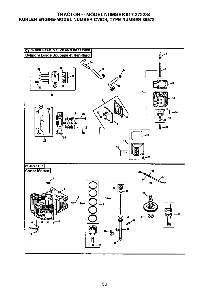
TRACTOR -- MODEL NUMBER 917.272234
KOHLERENGINE-MODELNUMBERCV624,TYPENUMBER65578
/i
j
I--
']1
_.n,.,_"_ .
50
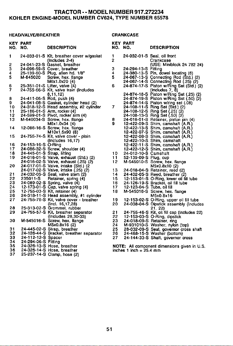
TRACTOR- - MODEL NUMBER 917.272234
KOHLER ENGINE-MODEL NUMBER CV624, TYPE NUMBER 65578
HEADNALV_BREATHER CRANKCASE
KEY PART KEY PART
NO. NO. DESCRIPTION NO. NO. DESCRIPTION
1 24-033-01-S Kit, breather cover w/gasket 1 24-032-01-S Seal, oil front
(Includes 2-4) 2 Crankcase
2 24-041-23-S Gasket, breather (USE: Miniblock 24 752 24)
3 24-096-59-S Cover, breather 3 24-294-13-S Fitting
4 25-139-60-S Plug, allen hd. 1/8" 4 24-380-13-S Pin, dowel locating (6)
5 M-645020 Screw, hex. flange 5 24-067-13-S Connecting Rod (Std.) (2)
M6xl.Ox20 (4) 24-667-14-S Connecting Rod (.25) (2)
6 25-351-01-S Lifter, valve (4) 6 24-874-17-S Piston wiring Set (Std.) (2
7 24-755-66-S Kit, valve train (Includes (Inc]odes 7, 8)
8,11,12) 24-574-18-S P_ston w/Ring Set (.25) (2)
8 24-411-05-S Rod, push (4) 24-874-19-S Piston wiring Set (.50) (2)
9 24-041-08-S Gasket, cylinder head (2) 24-874-14-S Piston wiring set (.08)
16 24-318-12-S Head assembly, #2 cylinder 7 24-108-11-S Ring Set (Std.) (2)
11 25-186-01-S Arm, rocker 4) 24-108-12-S Ring Set (.25)(2)
12 24-599-01-S Pvot, rockerann 4 24-108-13-S Ring Set( ).50 ()2
13 M-646034-S Screw, hex. 8ange 8 24-018-01-S Retainer, piston pin (4)
M6xl.0x34 (4) 9 12-422-09-S Shim, camshaft (A.R.)
14 12-086-16-S Screw, hex flange 12-422-13-S Shim, camshaft (A.R.
M1Oxl,Sxg0 (8) 12-422-07-B Sh m, camshaft A,R.
15 24-755-74-S Kit. valve cover - plain 12-422-05-S Shim, camshaft (A,R.)
(Includes 16,17) 12-422-10-S Shim, camshaft
16 24-153-16-S O-Ring 12-422-11-S Shim, camshaft (A.R.)
17 24-086-32_S Screw, shoulder (4) 12-422-12-S Shim, camshaft (A.R.)
18 24-445-01-S Strap, lifting 10 24-012-10-S Camshaft
15 24-016-01-S Valve, exhaust (Std.) (2) 11 52-139-09-S Plug, cup
24-016-02-S Valve, exhaust (.25) (2) 12 M-545010-S Screw, bex. 8ange
25 24-617-01-S Valve, intake (Std.) (2 M5x0.6xl0 (2)
24-017-02-S Valve, intake .25) (2) 13 24-018-04-S Retainer, reed (2)
21 24-032-05-S Sea, valve stem (2) 14 24-402-05-S Reed, breather (2)
22 235011-S Retainer, spdng (4) 15 12-153-01-S O-Ring, lower oil fill tube
23 24-089-02-S Spring, valve (4) 16 24-126-19-S Bracket, oil fill tube
24 12-173-01-S Cap, valve spring (4) 17 12-123-04-S Tube, oil lill
25 12-755-03-S Kit, retainer (4) 18 M-545016-S Screw, hex. flange
26 24-315-11-S Head assembly, #1 cylinder MSx0.8x16
27 24-755-76-S Kit, valve cover - breather 19 12-153-02-S O-Ring, upper oil fill tube
(Incl. 16,17,28) 20 24-038-04-S Dipstick assembly (Includes
28 25-313-02-S Grommet, rubber 21, 22)
29 24-755-57-S Kit, breather separator 21 24-755-46-S Kit, oil f_l cap (includes 22)
(includes 28,30-33) 22 12-153-03-S O-Ring, dipstick
30 M-545616-S Screw, hex. flange 23 24-018-69-S Retainer, ring
M5x0.Sx16 (2) 24 M-931010-S Washer, nylon (top)
31 24-445-02-S Strap, breather 25 28-032-09-S Seal, governor cross shaft
32 24-126-44-S Bracket, breather separator 26 24-468-15-S Washer (bottom)
33 24-112-12-S Spacer 27 24-144-33-S Shaft, governer cross
34 24-294-06-S Fitting
35 24-326-13-S Hose, breather NOTE: All component dimensions given in U.S.
36 24-326-14-S Hose, breather inches 1 inch = 25.4 mm
37 25-237-14-S Clamp, hose (2)
51
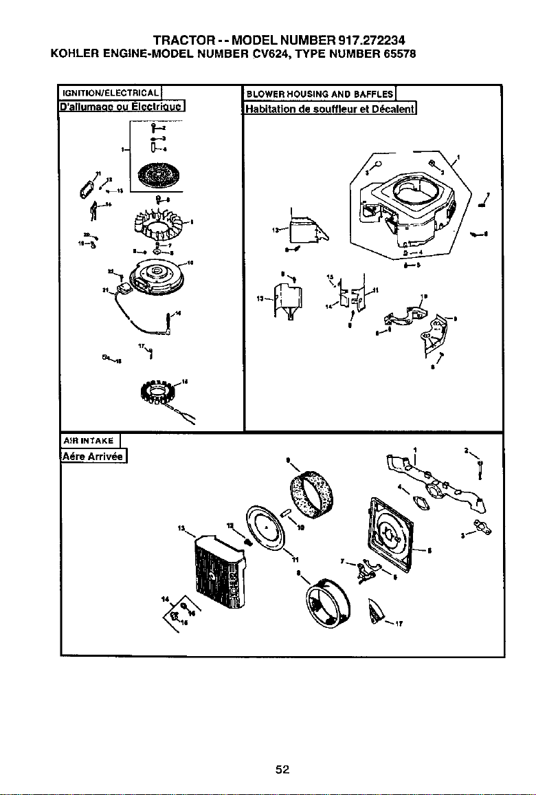
TRACTOR - - MODEL NUMBER 917.272234
KOHLERENGINE-MODELNUMBERCV624,TYPENUMBER65578
IGNITION/ELECTRIC AL
D'alluma(ze ou ElectriQue
f-,
t4
BLOWER HOUSING AND BAFFLES I
Habitation de souffleur et D_calentl
I
52
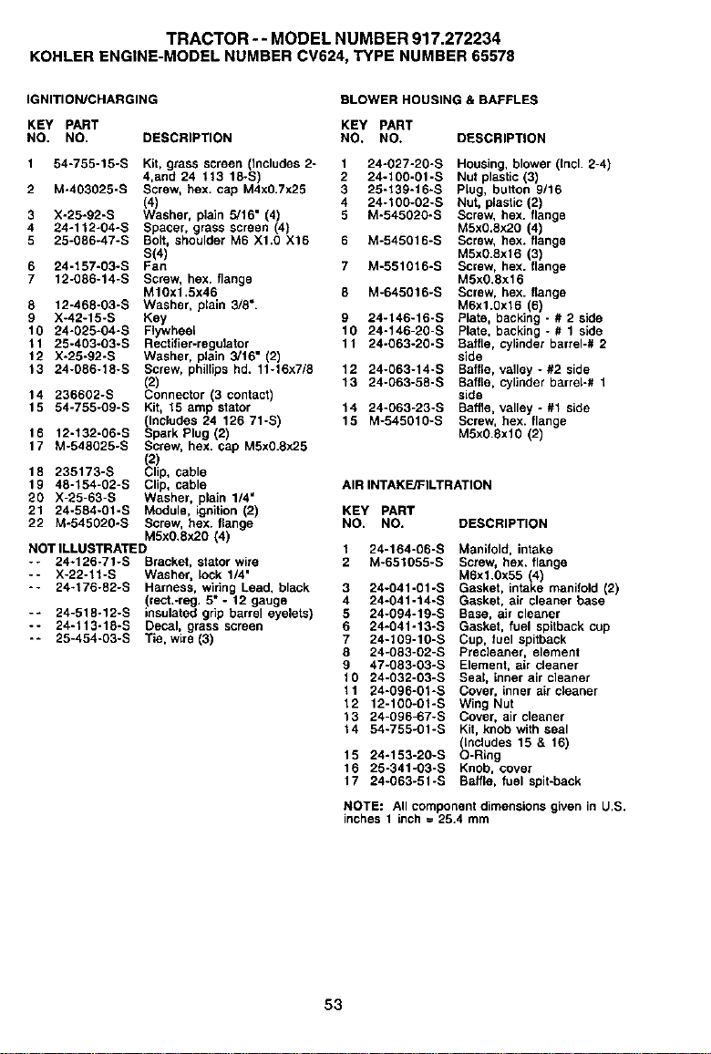
TRACTOR--MODELNUMBER917.272234
KOHLERENGINE-MODELNUMBERCV624,TYPENUMBER65578
IGNITION/CHARGING BLOWER HOUSING & BAFFLES
KEY PART KEY PART
NO. NO. DESCRIPTION NO. NO. DESCRIPTION
1 54-755-15-S Kit, grass screen (Includes 2-
4,and 24 113 18-S)
2 M-403025-S Screw, hex. cap M4x0.7x25
(4)
3 X-25*92-S Washer, plain 5/16" (4)
4 24o112-04-S Spacer, grass screen (4)
5 25-086-47-S Bolt, shoulder M6 X1.0 X16
S(4)
6 24-157-03-S Fan
7 12-086-14-S Screw, hex. flange
M10x1.5x46
8 12-468-03-S Washer, plain 3/8".
9 X-42-15-S Key
10 24-025-04-S Flywheel
11 25-403-03-S Rectifier-regulator
12 X-25-92-S Washer, plain 3/16" (2)
13 24-086-18-S Screw, phillips hd. 11-16x7/8
(2)
14 236602-S Connecter (3 contact)
15 54-755-09-S Kit, 15 amp stator
(Includes 24 126 71-S)
16 12-132-06-B Spark Plug (2)
17 M-548025-S Screw, hex. cap MSx0.ex25
18 235173-S _21!p,cable
19 48-154-02-S Clip, cable
20 X-25-63-S Washer, plain 1/4"
21 24-584-01-S Module, ignition (2)
22 M-545020-S Screw, hex. flange
M5x0,8x2O (4)
NOT ILLUSTRATED
-- 24-126-71-S Bracket, stator wire
-- X-22-11-S Washer, lock 1/4"
-- 24-176-82-S Harness, wiring Lead, black
(rect.-reg. 5" - 12 gauge
-- 24-518-12-S insulated grip barrel eyelets)
-- 24-113-18-S Decal, grass screen
-- 25-454-03-S Tie, wire (3)
1
2
3
4
5
9
10
11
12
13
14
15
24-027-20-S Housing, blower (Incl. 2-4)
24-100-01-S Nut plastic (3)
25-139-16-S Plug, button 9/16
24-100-02-S Nut, plastic (2)
M-545020-S Screw, hex. flange
M5x0.8x20 (4)
M-545016-S Screw, hex. flange
MSxO.ext 6 (3)
M-551016-S Screw, hex. flange
M5x0.8x16
M-645016-S Screw, hex. flange
M6x1.0x16 6)
24-146-16-S P ate, back ng - # 2 side
24-146-20-S Plate, backing - # 1 side
24-063-20-S Baffle, cylinder barrel-# 2
side
24-063-14-S Baffle, valley - #2 side
24-063-58-S Baffle, cylinder barrel-# 1
side
24-063-23-S Baffle, valley - #1 side
M-545010-S Screw, hex. flange
M5xO.8xf 0 (2)
AIR INTAKE/FILTRATION
KEY PART
NO. NO. DESCRIPTION
24-164-06-S
M-651055-S
3 24-041-01 -S
4 24-041-14-S
5 24-094-19-S
6 24-04f-13-S
7 24-109-10-S
8 24-083-02-S
9 47-083-03-S
10 24-032-03-S
11 24-096-01-S
12 12-100-01-S
13 24-096-67-S
14 54-755-01-S
15 24-153-20-S
16 25-341-03-S
17 24-063-51-S
Manifold, intake
Screw, hex. flange
M6xl.0x55 (4)
Gasket, intake manifold (2)
Gasket, air cleaner base
Base, air cleaner
Gasket, fuel apitback cup
Cup, fuel apitback
Precleaner, element
Element, air cleaner
Seal, inner air cleaner
Cover, inner air cleaner
Wing Nut
Cover, air cleaner
Kit, knob with seal
(includes 15 & 16)
O-Ring
Knob, cover
Baffle, fuel spit-back
NOTE: All component dimensions given in U.S,
inches 1 inch = 25,4 mm
53
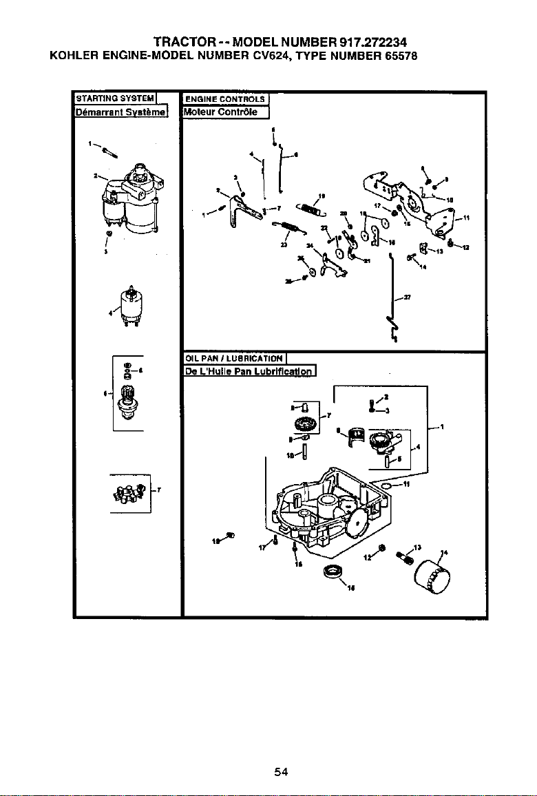
TRACTOR - - MODEL NUMBER 917.272234
KOHLERENGINE-MODELNUMBERCV624,TYPENUMBER65578
STARTINGSYSTEM I
Ddmarrant Svst_me_
t
$
m
6"
ENGINE CONTROLS
Moteur Contr_le
.__II_°_,,,_:,
I:U
OILPAN ! LUBRICATIONI
De L'Hulle Pan Lubriflcatlon I
m
.T I l_
O1°'
,._0 tP'
54
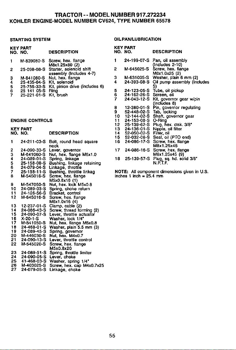
TRACTOR -- MODEL NUM BER 917.272234
KOHLER ENGINE-MODEL NUMBER CV524, TYPE NUMBER 65576
STARTING SYSTEM
OIL PAN/LU BRICATION
KEY PART KEY PART
NO. NO. DESCRIPTION NO. NO.
1 M-839080-S Screw hex. flange
MSxl.25xSO 2)
2 25-098-08-S Starter, solenoid shift
assembly (Includes 4-7)
3 M-841080-S Nut, hex. flange
4 25-435-04-S Kit. solenoid
5 25-755-33-S kit, pinion dine _tcl_hes 67
6 25 141 05-S Ring
7 25-221-01-S Kit, brush
ENGINE CONTROLS
KEY PART
NO. NO.
DESCRIPTION
Bolt, round head square
neck
Lever, governor
Nut, hex. Mange M6xl.g
Spring, linkage
Bushing, linka e retaining
Linkage, thro_
Bushin , throttle linkag
Sctew,ghex. f_ange
M5xO.gxl 6 (1)
Nut, hex. lock M5x0.8
Spring, choke return
Bracket, control
Screw, hex. ftange
M6x1.0x16 4)
Clamp, cable 2
Screw, thread forming (2)
Lever, throttle actuator
Washer, lock 1/4"
Nut, hex. flange M5x0.8
Washer, plain 5.5 mm (3)
Spring, governor
Nut, hex. M4x0.7
Lever, throttle control
Screw, hex. flange
M5xO.8x20
Spr;ng, throttle limiter
Lever, choke
Washer, spring 1/4"
Screw, hex. cap M4xO.Tx25
Linkage, choke
1 24-211 "O3"S
2 24-g90-33-S
3 M-641060"S
4 24-089-01 -S
5 25-158-08oS
6 24-079"04"S
7 25-158"11"S
8 M-545B'=6-S
9 M-547050-S
10 24-089-03-S
11 24-126-56-S
12 M-64501B-S
13 12-237-01-S
14 24-086-43-S
15 24-090-07-S
16 X-20-1-S
17 M-541050-S
18 24-468-01-S
19 24-089-45-B
20 M-446030-S
21 24°090-13-S
22 M-545020-S
23 24-089-51-S
24 24-090-05-S
25 41-468-03-S
26 M-403025-S
27 24-079-05-S
DESCRIPTION
1 24.199.07-S Pan. oil assembly
(thcludes 2-_.0_
2 M-645025-S Screw, hex. flange
M6xl.OX25 (2)
3 M-631005-S Washer, plain 6 mm (2)
4 24-393-g8-s Oil pump assembly (Includes
5 24-123-05-S "_Jbe, oil pickup
6 24-162-26-S Screen, oil
7 24-043-12-S Kit, governor gear w/pin
(Includes 8)
8 12-380-01-S Pin, governor regulating
9 52-448-02-S Tab, locking
10 12-144-02-S Shaft, governor gear
11 24-153-08-S O-Ring
12 25-139-62-S Plug, hex. ctsk. 3/8"
13 24-136-01-S Nipple, oil filter
14 52-050-02-S Filter, Bit
15 52-032-08-S Seal, oil (PTO end)
16 24-086-17-S Screw, hex. flange
M8x1.25x45
17 24-086-16-S Screw, hex. flange
MBxl.25x45 (9)
18 25-139-57-S Plug, sq. hd. solid 3/8"
N.P.T.F.
NOTE: All component dimensions given in U.S.
inches t k_h = 25.4 mm
55
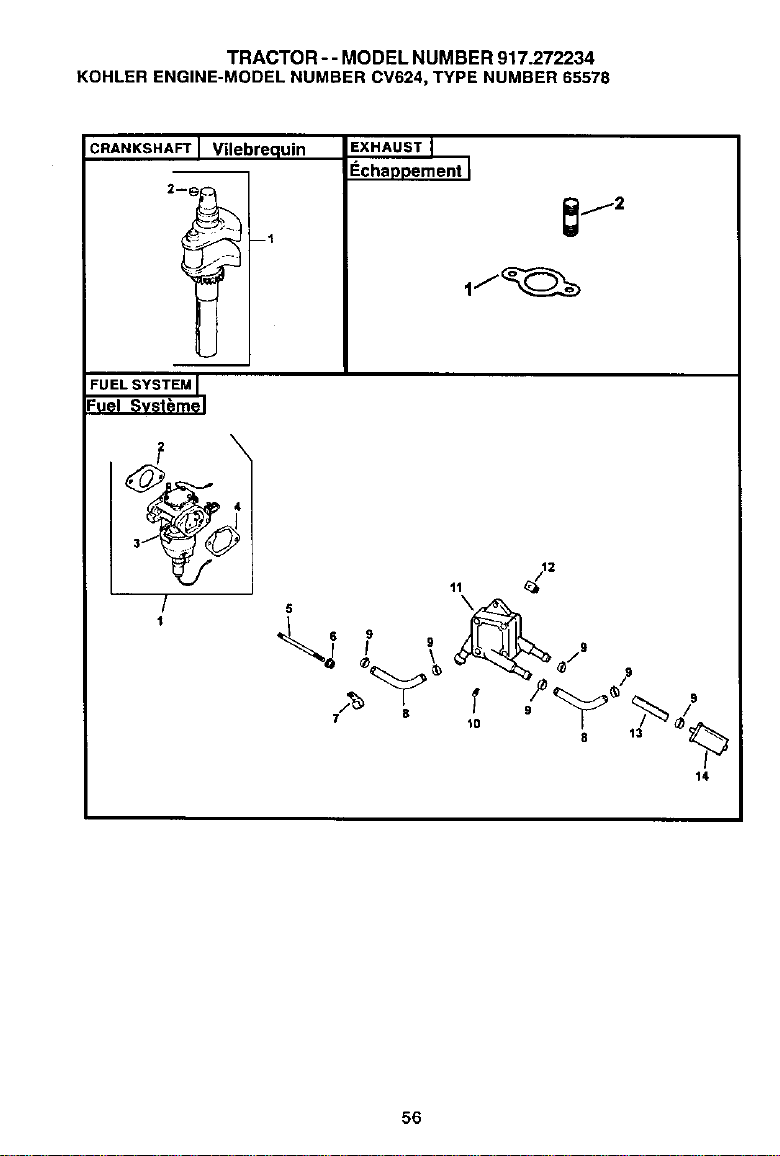
TRACTOR-- MODEL NUMBER 917.272234
KOHLER ENGINE-MODEL NUMBER CV624, TYPE NUMBER 65578
CRANKSHAFT I Vilebrequin EXHAUST
Echa;)Dement
FUEL SYSTEM
Fuel Svst_me
4
/
t
T
14
5
7 8
56
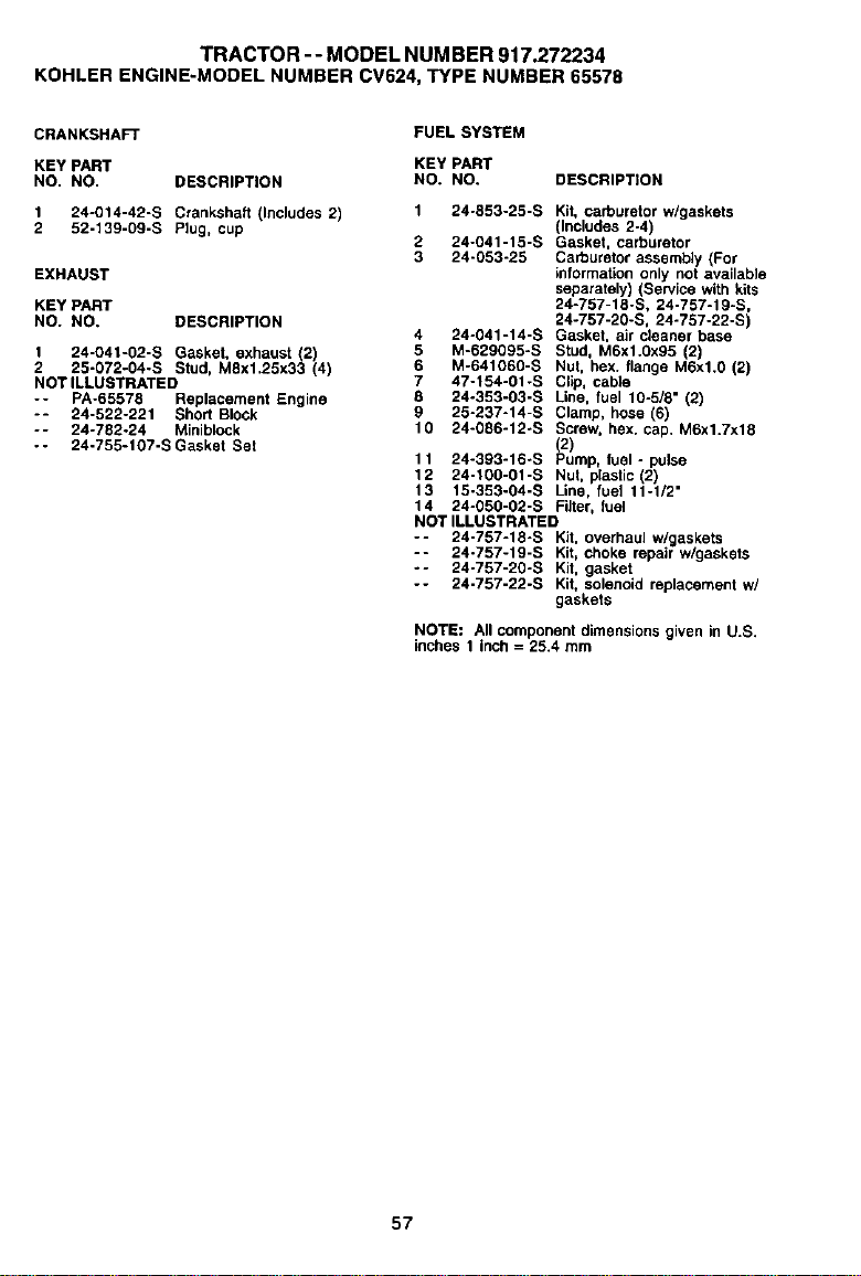
TRACTOR -- MODEL NUMBER 917.272234
KOHLER ENGINE-MODEL NUMBER CV624, "P/PE NUMBER 65578
CRANKSHAFT
FUEL SYSTEM
KEY PART KEY PART
NO. NO. DESCRIPTION NO. NO.
1 24-014-42-S Ctanksha_ (Includes 2) 1 24-853-25-S
2 52-139-09-S Ptug, cup 2 24-041-15-S
3 24-053-25
EXHAUST
KEY PART
NO. NO, DESCRIPTION
4 24-041-14-S
1 24-041-02-S Gasket, exhaust (2) 5 M-629095-S
2 25-072-04-S Stud, M8x1.25x33 (4) 6 M-641050-S
NOT ILLUSTRATED 7 47-154-01-S
8 24-353-03-S
-- PA-65578 Reptacement Engine
-- 24-522-221 Short Block 9 25-237-14-S
-- 24-722-24 MIniblock 10 24-086-12-S
- - 24-755-107-S Gasket Set
DESCRIPTION
Kit, carburetor w/gaskets
(Includes 2-4)
Gasket, carburetor
Carburetor assembly (For
information only not available
separately) (SewIce with kits
24-757-15-S, 24-757-19-S,
24-757 -2_,-S, 24-757-22-S)
Gasket, air cleaner base
Stud, M6xl.0x95 (2)
Nut, hex. flange M6xl.0 (2)
Clip, cable
L;.ne, fuet 15-518" (2)
Clamp, hose (6)
Screw, hex. cap. M6x1.7x18
(2)
11 24-393-16-S Pump, fuel - pulse
12 24-100-01-S Nut, plastic (2)
13 15-353-04-S Line, fuel 11-1/2"
14 24-050-02-S Filter, fuel
NOT ILLUSTRATED
-- 24-757-18-S Kit, overhaul w/gaskets
-- 24-757-19-S Kit, choke repair w/gaskets
-- 24-757-20-S Kit, gasket
-- 24-757-22-S Kit, solenoid replacement w/
gaskets
NOTE: All componentdimensionsgiven in U.S.
inches 1 inch = 25,4 mm
57

58

SUGGESTED GUIDE FOR SIGHTING SLOPES FOR SAFE OPERATION
O1
(O
ONLY RIDE UP AND DOWN HILL,
NOT ACROSS HILL
Operate your Tractor up and down the face of slopes (not
greater than 15 ), never across the face. Make turns gradu-
ally to prevent tipping or Joss of control. Exercise extreme
caution when changing direction on slopes.
HI .........

Forrepairofmajorbrandappliancesin your own home...
no matterwhomade it,nomatterwhosoldit!
1-800-4-MY-HOME _ Anytime.dayorr_ht
(1-8CX).469-4663) (U.S_. and Canada)
www,seQrs,com www.._B_r_ca
Forrepairof cany-inproductslikevacuums,lawnequipment,and
electronics,callforthe nearestSearsParts and RepairCenter.
1-800-488-1222 Any'drne,dayorr_ght(U.S,A,only)
wvtPN.se_ll_.com
Forthe replacementparts,accassoriesandownersmanuals
that youneedto de-it-yourself,callSearsPartsDirectSM!
1-800-386-PART 6a.m.- 11wn., 7days aweek
(1-8(X)-366-7278) (U.SJ_. only)
www.se_rs.conVpadsdirect
To purchase or inquire about a Sears Service Agreement
or Sears Maintenance Agreement
1-800-827-6655 (u.8_.) 1-800-361-8665 (Canada)
7aJ_ - 5 p.m.,CST,Mor_- SaL 9 aJ_.- 8 pJ_.EST,M- F,4p.m.Sat
Parapecr_sewiciodempataciSna Au Canadapoursewiceenf_:
domic_Tio,y pataon:lenarpezas: 1.600.LE.FOYERMC
1-888-SU-HOGARsM (1_00-533_937)
(1-888-784-6427) v,_w.seats.ca
® Registered Trademark / "_uTrademark / sMSen/ice Mark of Sears, Roebuck and Co.
® Marca Registrada / TMMarca de F_brica / sa Mama de Setvicio de Sears, Roebuck and Co.
_: Marque de commerce / uo Marque d_pos_e de Sears, Roebuck and CO,
180168 7.17.01 TR Printed in U.S.A.
