Loading ...
Loading ...
Loading ...
9
3.5 INSTALLING NON-INSULATED DUCTS AND DIFFUSERS (CONT’D)
Stale air exhaust ductwork
Same as for Fully Ducted System, described in step 3.5.1.
3.5.2 CENTRAL DRAW POINT (AS ILLUSTRATED IN SECTION 1.2)
Fresh air distribution ductwork
When performing duct connections, always use approved tools and materials. Respect all corresponding
laws and safety regulations. Please refer to your local building code.
WARNING
!
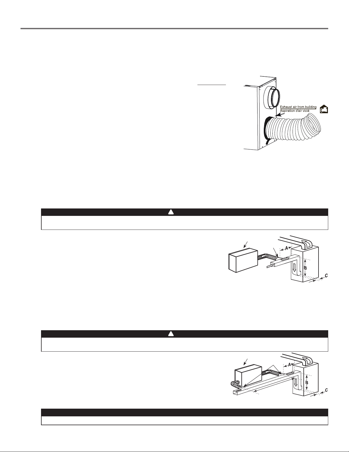
• Locate the opening for fresh air ductwork on the forced air unit return duct
at a minimum linear distance of 9’ 10” (3 m) upstream (from forced air unit drop:
A+B+C). Cut out a 5” Ø hole in this location, using metal shear.
• Use a metal transition (not included, available in hardware store) to connect the
unit duct to the forced air unit return duct.
• Attach the other end of the flexible duct to the fresh air to building port (see
icon on the left side of the unit). Use tie wrap and duct tape to seal the connection.
See illustration at right.
3.5.1 FULLY DUCTED SYSTEM (AS ILLUSTRATED IN SECTION 1.1) (CONT’D)
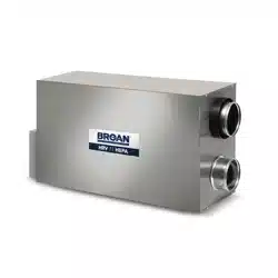
HOW TO CONNECT THE FLEXIBLE DUCTS TO THE UNIT PORTS
Both flexible ducts attached to the diffusers must be connected to the bottom ports of
the unit. When facing the unit door, the fresh air to building port is located on left side
and the exhaust air from building port is on the right side. Refer to the identification
labels affixed beside each unit ports. Using tie wrap, attach the fresh air to building
duct to its corresponding port, then do the same for the exhaust air to building duct
and port. See illustration at right.
NOTE: Use an insulated duct (not included) if the duct will have to go through a
space where it is possible to experience extreme temperature conditions
(eg: in northern area, not unheated attic in winter or uncooled attic in southern
area). Also, if you plan to stop the unit for more than 12 hours, we recommend
to cover the duct with R12 insulation.
VJ0159
RIGHT SIDE OF THE UNIT
3. INSTALLATION (CONT’D)
VJ0099
A + B + C = NOT LESS
THAN 9’ 10” (3 M)
UNIT DOOR
METAL
TRANSITION
Fresh air distribution ductwork (return side connection)
Same as for Central Draw Point, described in step 3.5.2.
3.5.3 SIMPLIFIED INSTALLATION (AS ILLUSTRATED IN SECTION 1.3)
Stale air exhaust ductwork (return side connection)
When performing duct connections, always use approved tools and materials. Respect all corresponding
laws and safety regulations. Please refer to your local building code.
WARNING
!
• Locate the opening for stale air ductwork on the forced air unit return duct at
least 3’ (0.9 m) from fresh air ductwork connection. Cut out a 5” Ø hole in this
location, using metal shear.
• Use a metal transition (not included, available in hardware store) to connect the
unit duct to the forced air unit return duct.
• Attach the other end of the flexible duct to the exhaust air from building port (see
icon on the right side of the unit). Use tie wrap and duct tape to seal the connection.
See illustration at right.
The furnace blower must be running when the ventilation unit is in operation.
CAUTION
VJ0100
3’ (0.9 M)
MINIMUM
UNIT DOOR
A + B + C = NOT LESS
THAN 9’ 10” (3 M)
METAL
TRANSITIONS
Loading ...
Loading ...
Loading ...