Loading ...
Loading ...
Loading ...
13
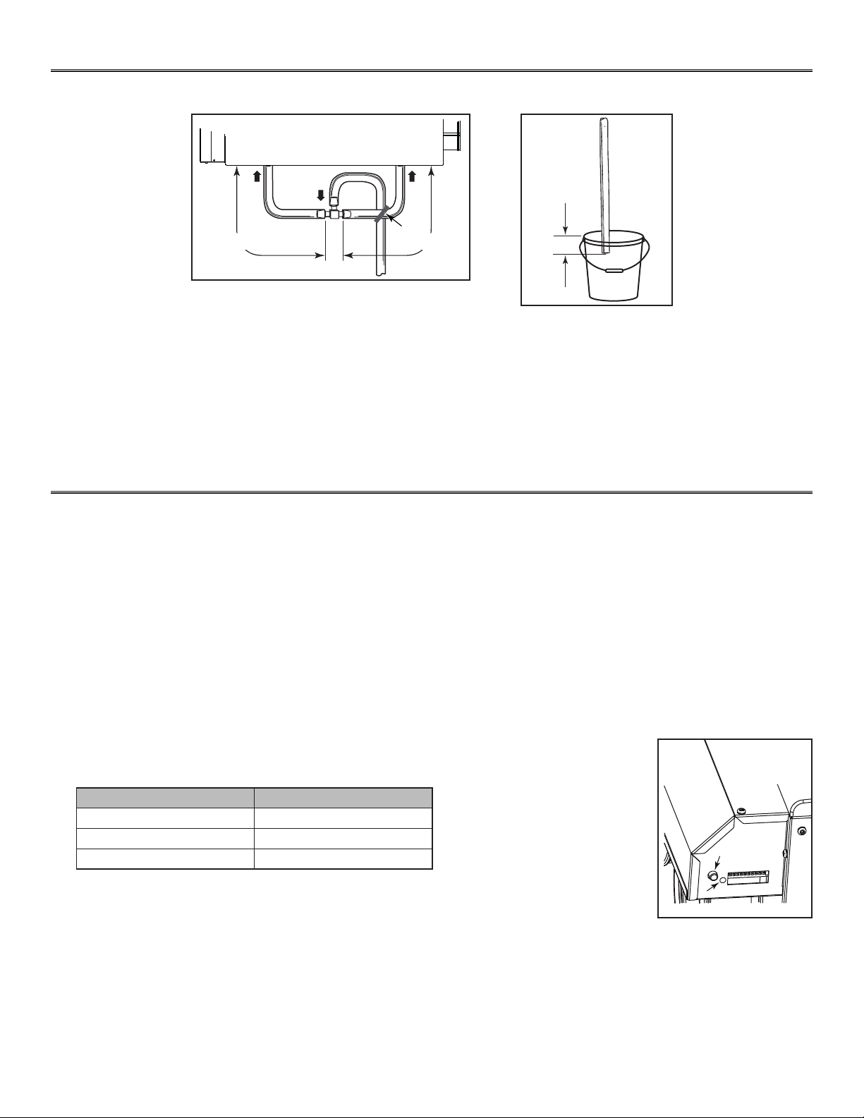
3.8 CONNECTING THE DRAIN
Cut two sections of plastic tubing, approximately
12” long, and connect each one to both inner drain
fittings located under the unit as shown.
Join these both sections to the “T” junction and
main tube as shown, to prevent the unit from
drawing unpleasant odors from the drain source.
VD0308A
± 1”
Run the tube to the floor
drain or to an alternative
drain pipe or pail.
IMPORTANT
If using a pail to collect
water, locate the tube end
approximately 1” from the
top of the pail in order to
prevent water from being
drawn back up into the unit.
VD0513A
± 12” ± 12”
TIE WRAP
3. INSTALLATION (CONT’D)
4. CONTROLS
This unit is equipped with an integrated defrost control located under the electrical compartment of the unit. Plug the unit.
4.1 BOOTING SEQUENCE
The unit booting sequence is similar to a personnal computer boot sequence. Each time the unit is plugged after being unplugged, or
after a power failure, the unit will perform a booting sequence before starting to operate.
During the booting sequence, the integrated defrost control LED (2 in illustration below) will be OFF for 3 seconds, and then will turn
RED for the rest of the booting sequence (approximately 15 seconds). During this RED light phase, the unit is checking and resetting
the motorized damper position. Once the motorized damper position completely set, the booting sequence is done; the color of the
LED will show on which defrost cycle the unit is set.
NOTE: No command will be taken until the unit is fully booted.
4.2 DEFROST CYCLES
Five seconds after the booting sequence is done, the LED (2) will light and stay lit to show in which
defrost cycle the unit is set. Use the push button (1) to change the defrost cycle of the unit (see table
below).
LED COLOR DEFROST CYCLE
GREEN STANDARD
RED PLUS
AMBER DISCRETION
If a problem occurs during the unit operation, its integrated control LED (2) will blink. The color of the blinking light depends on the
type of error detected. Refer to Section 7 Troubleshooting on last page for further details.
1
2
VD0310
According to your need, there are 3 defrost cycles available:
STANDARD: This is the factory set defrost cycle, which is the most commonly used to suit normal weather conditions. When
needed, the unit will perform defrost cycle on high speed.
PLUS: This mode has been created for people who live in cold region (outside temperature -27°C [-17°F] and lower). This
setting makes the unit perform defrost cycle on high speed for a longer period of time.
DISCRETION: When needed, the defrost cycle will be performed on the same speed than the unit ventilation speed. For example,
if the unit is set on high speed, the defrost cycle will be done on high speed, but if the unit is set on low speed, the
defrost cycle will be done on low speed.
NOTE: There is a 15-minute delay for the new defrost cycle choice to be kept in memory; if a power
failure occurs during this time delay, when the power returns, the unit resume to its previous
setting.
Loading ...
Loading ...
Loading ...