Loading ...
Loading ...
Loading ...
8
3.5 INSTALLING NON-INSULATED DUCTS AND DIFFUSERS
Stale air exhaust ductwork
• Install the stale air exhaust diffuser in the main area where the contaminants are produced: kitchen, living room, etc. Position
the diffuser as far from the stairway as possible and in such a way that the air circulates in all the lived-in spaces in the house.
If desired, you can install another diffuser (sold separately).
• If a diffuser is installed in the kitchen, it must be located at least 4 feet (1.2 m) from the range.
• Install the diffuser 6 to 12 inches (152 to 305 mm) from the ceiling on an interior wall OR install it in the ceiling.
3.5.1 FULLY DUCTED SYSTEM (AS ILLUSTRATED IN SECTION 1.1)
Never install a stale air exhaust diffuser in a closed room where a combustion device operates, such as a
gas furnace, a gas water heater or a fireplace.
WARNING
!
Fresh air distribution ductwork
• Install the fresh air distribution diffuser in a large, open area in the lowest level to ensure the greatest possible air circulation.
• Keep in mind that the fresh air diffuser must be located as far as possible from the stale air diffuser. If desired, you can install
another diffuser (sold separately).
• Install the diffuser either in the ceiling OR 6 to 12 inches (152 to 305 mm) from the ceiling on an interior wall. (The cooler air
will then cross the upper part of the room and mix with room air, before descending to occupant’s level.)
• If a register must be floor installed, direct the airflow up the wall.
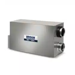
HOW TO CONNECT THE FLEXIBLE DUCTS TO THE DIFFUSERS
Once the diffusers location is determined, cut out 5¼” diameter hole.
Run one end of the flexible duct through the hole and fix it to the diffuser base (1),
using a tie wrap and duct tape. Assemble the diffuser base to the wall (or ceiling
using its 4 no. 8 x 3/4” screws. Then, slide in the diffuser (2).
See illustration at right.
Ø 5¼”
VJ0094A
2
1
3. INSTALLATION (CONT’D)
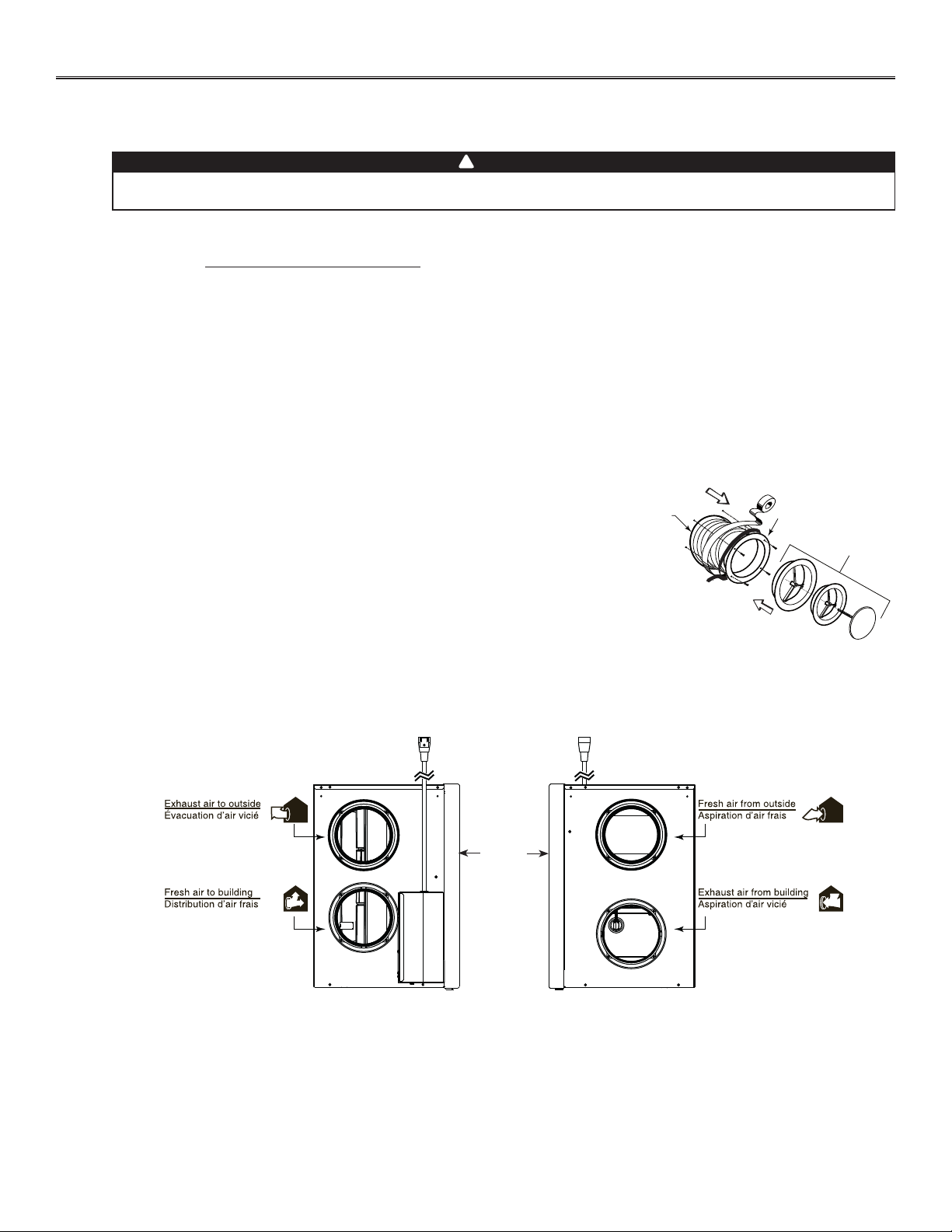
UNIT PORTS IDENTIFICATION
Each unit port has an identification label beside it to avoid wrong duct connections to the unit. Always refer to these labels before
performing any duct and port connection.
VJ0158
UNIT
DOOR
Loading ...
Loading ...
Loading ...