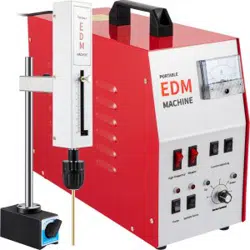
EDM
PORTABLE EDM
TAP BREAKING MACHINE
高端画册好品牌
INTEGRITY
EXCELLENCE
RESPONSIBILITY
REVIVAL
INSTRUCITIONS
MADE IN CHINA

高端画册好品牌
Dear users:
First of all, thank you for choosing the portable EDM tap machine
breaking carefully produced by our company for you.
Our company's high - speed take out the broken tap machine has
advanced design and excellent performance. The selection of our
products proves that you have high requirements for the performance
and service of machine tools.
Please read this manual carefully! This manual aims to make you
familiar with the operation method of this machine tool, the problems
that should be paid attention to in use and the maintenance measures
that should be followed, so as to ensure that you can get better
processing effect, extend the service life of the machine tool and
reduce the failure.
Special statement:
This manual includes the latest information up to the time
when this manual is printed. The company is solely responsible for
the revision and explanation of this manual, and reserves the right
to improve the product at any time after printing without notice.
Some pictures in this manual are schematic drawings for reference
only. If the pictures are inconsistent with the real objects, the
real ones shall prevail.
System parameters and composition.................1
Power section.....................................2
Mechanical part...................................4
Operating instructions............................6
Processing example................................10
Special notes (must see)..........................13
Other processing methods..........................14
Causes of common taps breaking and preventive measures.......15
catalogue
高端画册好品牌
II,Power section
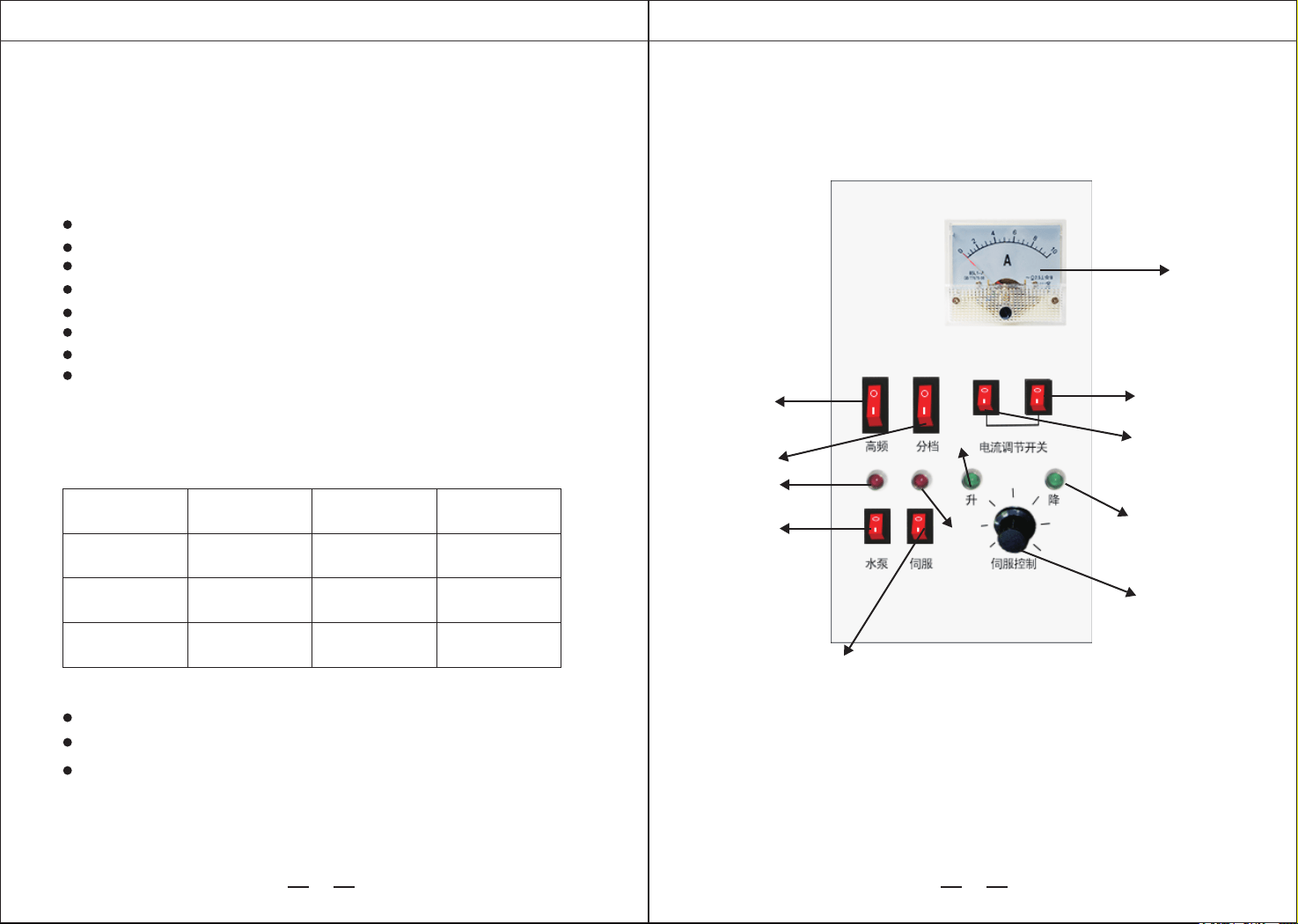
1、operation panel
Front
Operating panel instructions
1
3
2
4
5
6
7
8
9
10
11
12
PORTABLE EDM MACHINE PORTABLE EDM MACHINE
1 2
I, system parameters and composition
Outline size
1. Main parameters and technical indicators
long
power box
356mm 160mm 280mm
200mm 50mm 360mm
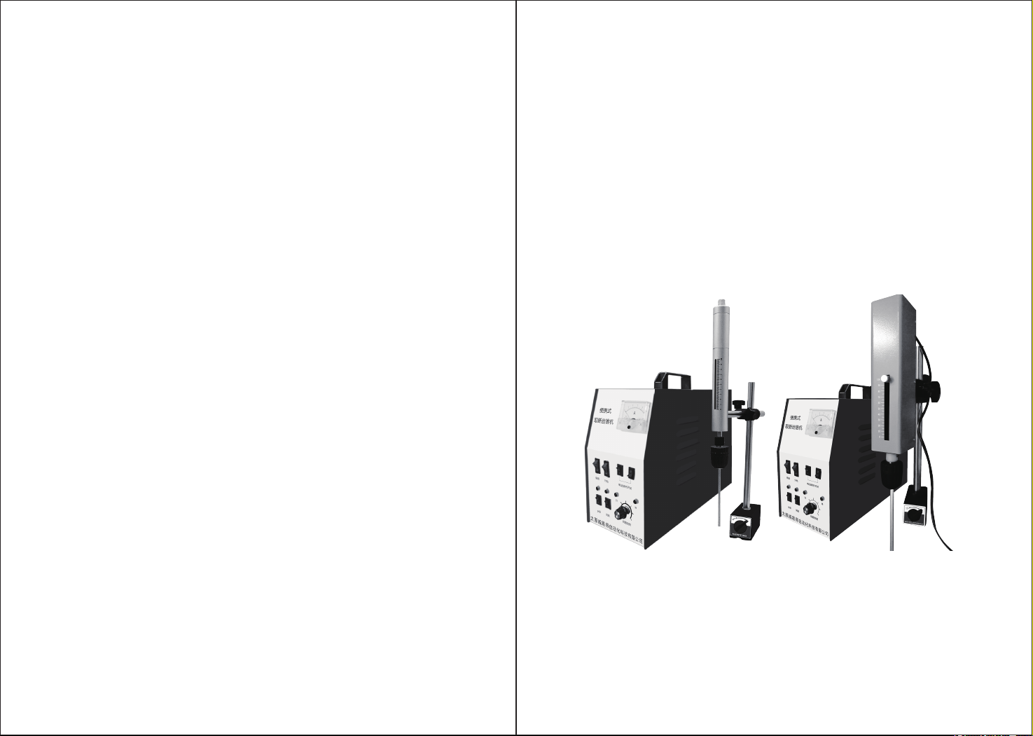
Processing device 1
Processing device 2
200mm 55mm 360mm
width high
2, component
power box
mechanical device
Auxiliary devices (magnetic gauge base, water pipe of magnetic base,
electrode chuck and accessories) .Other electrodes can also be
customized to customer needs.
Input power requirement-AC 220V/110V 6A
spindle servo stroke -100mm
Maximum power consumption -- - 400 w / 500 w / 600 w / 800 w
output voltage -- -- -- - 10-70 v
Clamping electrode diameter ---0.8-10mm
Maximum processing speed -- about 1mm/min
net weight: 13~15kg
Working fluid: clean tap water/pure water/distilled water/elec-
tric spark fluid/kerosene (pay attention to fire prevention)
High-frequency
Pump
Spindle Servo
DowmUp
Servo Control
Stepper Current Adjusting
1.Ammeter 2. Processing current switch(1)
3.Processing current switch(2) 4.Down indicator
5. Spindle servo control knob 6. Spindle servo switch
7. Pump switch 8. Pump Indicator 9. Stepper Switch
10. High-frequency Power Switch 11. Servo Indicator
12. Lift indicator

高端画册好品牌
PORTABLE EDM MACHINE PORTABLE EDM MACHINE
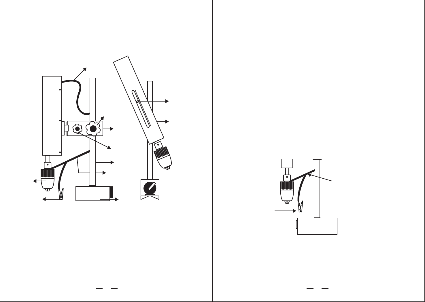
III,The mechanical partBack
13
14
15
16
18
17
Operating panel instructions
22
27
28
26
25
21
19
3 4
ON OFF
10 2 3 4 5 6 7 8 9 10
10 2 3 4 5 6 7 8 9 10
20
23
19. Electrode chuck 20. Electrode wire clamp (clamp work
piece) 21. Spindle head rotation control handle 22. Lift shaft
23. Lift arm lock handle 24. Lifting arm 25. Electrode line 26.
Magnetometer seat 27. Servo power cord
28. The spindle can be rotated
24
(1) Processing device 1
Servo Output
Power
13.Fan 14. Spindle servo output interface
15. High-frequency negative terminal (blue) 16.
Pump Power
Interface
17. Main switch and safety seat
18. High frequency positive pole (red)
AC220V/110V 5A
Pump Power Interface
PORTABLE EDM MACHINE PORTABLE EDM MACHINE
5 6
(2)Processing device2
22
27
28
26
25
21
19. Electrode chuck 20. Electrode wire clamp (clamp work
piece) 21. Spindle head rotation control handle 22. Lift shaft
23. Lift arm lock handle 24. Lifting arm 25. Electrode line
26. Magnetometer seat 27. Servo power cord
28. The spindle can be rotated 29.Fixed depth pointer
24
29
ON OFF
19
20
10 2 3 4 5 6 7 8 9 10
23
IV、Operating instructions
1. Operation steps
1.1 placement of mechanical components
As required, place the mechanical part in an appropriate position and open the
magnetic switch of the magnetic gauge seat (26).
In order to make the spindle work smoothly, the magnetic gauge seat should be
placed on a relatively flat working surface.
1.2 power and connection
(1) After the servo control plug into the power box panel 14 interface, and lock.
(2)The electrode wire is connected to the high-frequency terminal 15, 18 interfac-
es (red for the positive pole, black for the negative pole), and locked.
(3) insert the power cord plug in the attachment box into the power interface 17,
and connect the other end to the 110V/220V power supply.
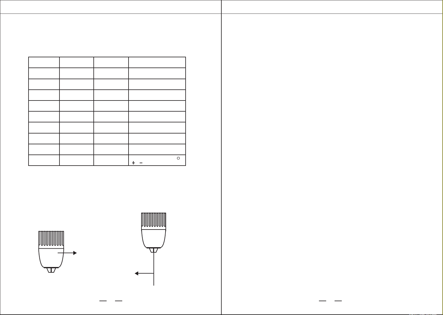
(4)Of the other end of the electrode line, respectively clamp workpiece and
twisted to the spindle head. As shown in figure:
1.3 connect the flushing pipe
Connect the attached water pipe to the submersible pump.
Connect the other end of the hose to the attached slug pipe for flushing,
then put the submersible pump into the water and finally insert the power
plug of the submersible pump into port 16 at the rear of the chassis.ii
10 2 3 4 5 6 7 8 9 10
Electrode line
Clamping the workpiece
PORTABLE EDM MACHINE PORTABLE EDM MACHINE
7 8
1.4 Installation Electrode
(1) Select and install suitable electrodes according to the need.
The size of the electrode can be chosen according to the size of the broken object.
The screw is equivalent to the drill bit.
For electrodes that are larger than the size of the drill chuck,
the auxiliary card holder in the optional attachment can be used.
The handle fork can be clamped below the thickness of 5mm sheet electrode
(optional accessories according to the actual need to contact our company to purchase). As shown
in figure (2)
Drill chuck
Electrode copper tube
Broken object
Tap M3
M4
M6
M8
M10
M3
M4
M6
OverM8
φ1.5
Electrodes should be as short
as possible to reduce jitter.
Electrodes should be as short
as possible to reduce jitter.
φ2
φ3
φ4
φ5
φ2.1
φ3.2
φ4.5
Take it out by hand
Tap
Tap
Tap
Tap
Drill bit
(screw)
Drill bit
(screw)
Drill bit
(screw)
Drill bit
(screw)
spec
Recommended
electrode diameter
Remark
1.5 start processing
(1)Switch on the power supply 17, adjust the spindle position and height,
pay attention to ensure that the electrode and the broken coaxial, so as
not to hurt the workpiece.
(2)After adjusting the position (center), open the water pump 7, open the
high frequency switch 10 after the outlet of the water pipe, press the
servo switch 6, rotate the servo adjusting knob 5 clockwise, rotate to the
center line to the right side of the center line and turn the indicator light
on, The spindle electrode starts to touch the workpiece gently, the lift
indicator lamp flashes alternately, starts the processing.
(3)according to the need, adjust the appropriate current 2m3 and spindle
service control 5 in time in order to achieve the appropriate processing
parameters (the potentiometer indicates that the second processing is
stable to the descending position).
Tip:
1. To ensure power access, remove rust and oil stains from the workpiece
surface before processing.
2. Some protective measures should be taken to avoid water splashing.
3. Experimental results show that immersion processing has better effect.
4. Electrode loss should be taken into account in processing.
1.6 stop steps
When the machining is not stable, the processing speed is accelerated,
or the hole below is found to start discharging, it is proved that the drill or
tap has been broken, then the machine can be shut down, the steps are as
follows:
(1)turn the servo adjusting knob 5 counterclockwise, Keep the rising
indicator light on, the spindle head starts to pick up the electrode after
leaving the workpiece, turn off the servo switch 6, turn off the water
pump 7
(2)turn off the high frequency power supply switch 10
(3)turn off the main power supply switch 17
2. Operation instructions
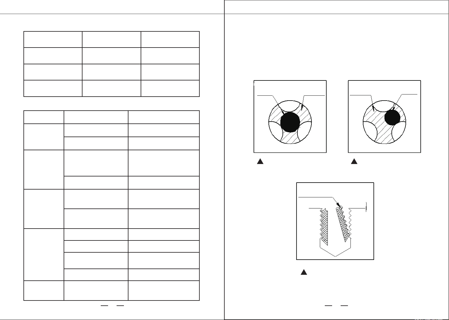
(1)Selection of processing parameters
Figure (2)
Recommended method: make a “ ”,
“ ”,“ ”, and screw it out
PORTABLE EDM MACHINE PORTABLE EDM MACHINE
9 10
V、processing examples
1、different sizes of broken tap processing
Remove small taps
electrode tap electrode tap
Residual tap
Removal of residues
Remove large taps
Current and Stepper Switch Refer to Table below:
⑵Faults and treatment methods
Electrode cross section
current regulating
switch 2, 3
level switch9
less than 1mm² Two off(low) off
1-3mm²
one open and one
close (medium)
open
greater than 3 mm²
Fault
phenomenon
1. Motor cable is not
properly connected
Reconnect the plug
contact our company in time2. Servo controller failure
1. High frequency power
cord not connected or
unattached
2. High frequency power
supply failure
1. The servo speed is not
suitablelure
2. The workpiece or
electrode is not clampede
4. To a certain depth
3. The water medium deviates
from the processing zone and
the liquid supply is less than
1. The polarity connection
of High Frequency Power
Line
2. Electrode diameter
smaller than 2mm current
and large
Adjust the polarity of the
high frequency line
Adjust current regulation
switch to reduce machining
current adjustment servo knob.
Adjust the height of the
workpiece and continue working
1. Related to local water quality
Replacement of purified or
distilled water
Adjust the position of the
flushing pipe
Reinstall the workpiece and
clamp the electrode
Adjust the servo knob to
stabilize the workpiece
contact our company in time
Connect the high frequency
power cord
cause Rule out way
two open (high)
open
The spindle is
not moving
after starting
the machine
Electrode does not
discharge after
contact with
workpiece
The processing
speed is fast and
stable, but the
interworking depth
is not deep, and the
electrode loss is
very large.
Unstable
machining,
swing back
and forth of
the electric
current meter
pointer,
relatively large
amplitude
Other conditions
are normal and
processing speed is
very slow
PORTABLE EDM MACHINEPORTABLE EDM MACHINE
11 12
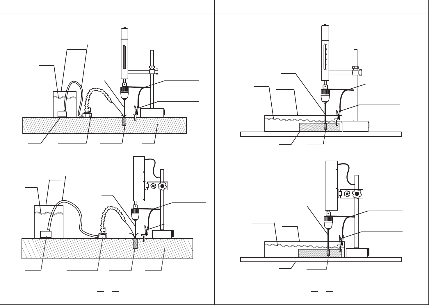
2、Water immersion diagram of small workpiece:
10 2 3 4 5 6 7 8 9 10
Water tank
2.Schematic diagram of large workpiece and processing:
10 2 3 4 5 6 7 8 9 10
electrode
electrode
Working fluid
Working fluid
Water tank
electrode
Working fluid
pump
Magnetic
flushing seat
Broken tap Broken tap
Broken tap
workpiece
workpiece
workpiece
pump
Magnetic
flushing seat
Broken tap workpiece
bucket
Water pipe
electrode
Working fluid
bucket
Water pipe
Processing device 1 Schematic Processing device 1 Schematic
Processing device 2 Schematic Processing device 2 Schematic
Electrode line
Clamping workpiece
Electrode line
Clamping workpiece
Electrode line
Clamping workpiece
Electrode line
Clamping workpiece
PORTABLE EDM MACHINE PORTABLE EDM MACHINE
1413
The following formula is generally used to calculate the bottom diameter of a
screw hole:
1. Tapping metric thread:
Pitch t<1 mm, dz=d-t ,t> 1 mm, dz=d- (1.04 ~1.06),t --pitch (mm)
dz-- diameter of drilling hole before tapping (mm)
d -- nominal diameter of thread (mm)
On the type of dz--diameter of drilling hole before tapping(mm)
d -- nominal diameter of thread (in.)
n -- number of teeth per inch
2. Inch screw thread
nominal diameter of thread Cast
iron and bronze
3/16" ~5/8"
3/4" ~11/2"
cast iron and bronze
dz =25 (d-1/n)
dz =25 (d-1/n)
Steel and brass
dz = 25 (d-1/n)+0.1
dz = 25 (d-1/n)+ 0.2
Special notes!!!
1. Please read the instruction carefully before operation!
2. It is equipped with external water pump, which is not under warranty,
Pay attention to the following when using:
Use clean tap water as working fluid. If pure water or distilled water is used,
the processing efficiency will be doubled.
If the circulating water is used, the water should be changed frequently,
otherwise the dirty water will seriously affect the processing efficiency. The
dirtier the water is, the lower the processing efficiency is, and the metal dregs in
the water will easily jam the main water pump, which will greatly reduce the
service life of the external water pump.
After using the circulating water, the external water pump needs to be
disassembled to clean up the metal residue left in the pump, which can greatly
extend the service life of the external water pump.
3. Every 3-4 hours of continuous work, the machine needs to rest for 30 minutes,
which can greatly extend its service life.
4. Prevent water and oil from the power supply and the moving part of the
machine to avoid failure.
5. If using spark working fluid or kerosene, be sure to pay attention to fire
prevention.During immersion processing, if using electric spark working fluid or
kerosene, be sure to pay attention to fire prevention, and it is safer if the liquid
level is more than 10 mm higher than the workpiece.
6. During the processing, the human body should not touch the electrode part at
the lower end of the spindle to prevent electric shock.
7. Do not work in dangerous environments, such as fire zones.
8. If there is no need for flushing, please turn off the power switch of water
pump. The water pump shall not operate without water.
9. During processing, water or other media must be used as working fluid. No
water processing is allowed, and the water volume must be sufficient. It is
forbidden to replace the water pump by manual flushing.
10. In the process of water working fluid processing, do not add antirust liquid
such as cutting fluid into the water, otherwise the processing efficiency will be
seriously affected.
11. The connection between the drill chuck and the processing device is made of
insulating material. Care should be taken during installation and use. Do not use
force or collision to prevent the insulation from breaking.
12. After the machine is processed, proper routine maintenance shall be done,
such as cleaning the dust and putting it in a dry place. The water on the drill
chuck shall be wiped dry and some lubricating oil shall be applied to prevent
rusting.
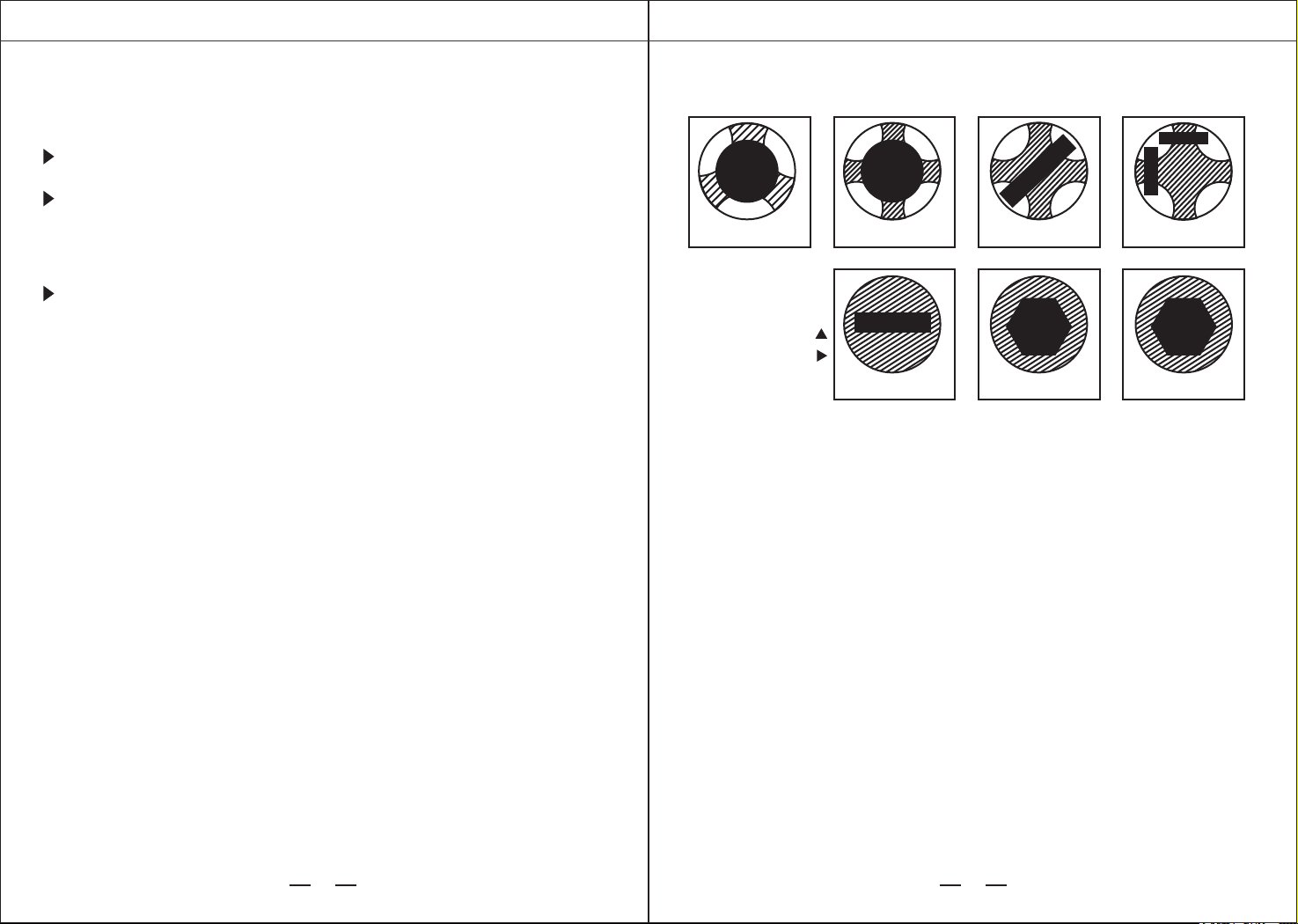
M2-M10 Tap
removal method
M10-M14 Tap
removal method
M12-M18 Tap
removal method
M18-M30 Tap
removal method
M6-M16 Screw
removal method
M16-M30 Screw
removal method
Extraction method of
extrusion tap above M10
Schematic diagram of other processing methods
electrode
tap
tap
Screw Screw
Extrusion
tap
tap
tap
electrode
electrode
electrode
electrode
electrode
electrode
Take out tap Sketch Map
Take out screw Sketch Map

PORTABLE EDM MACHINE PORTABLE EDM MACHINE
15 16
phenomenon, it seems to be the operator's skill problem., but actually is due to
insufficient tap structure. Currently used manual tap front are tapered, its
original face contact with the bottom hole is dot, silk cone and the bottom hole
concentricity all the skills and experience of the operator to maintain, should not
only keep the tap around perpendicular to the bottom hole end face, and remain
perpendicular to the bottom hole before and after the end, in a forced down the
tap equal strength from both hands at the same time screw tap.So many things
must be done at the same time, and it is difficult for a less skilled operator to do
so.Even if the technical level of the senior technicians, in the manual tapping
operation is not every time can grasp very accurately.
2.Prevention of tap breaking
(1)improve the structure of the tap. A cylinder with a length of 5 ~ 10mm and a
diameter the same as that of the drill bit for the bottom hole is added at the front
end of the head cone, which is used as the guiding part for the tap and the bottom
hole to automatically maintain concentric, so that the tap itself can automatically
maintain concentric with the bottom hole at the beginning of tapping.When
tapping with this kind of tap, it can avoid the phenomenon that the tap is broken
due to the different center of the tap and the bottom hole, and also can avoid the
phenomenon that the tap is broken due to the mismatch between the bottom
hole and the tap.At the same time, because it is impossible for the tap to enter
the bottom hole which does not match the tap, it can effectively prevent the
operator from misusing the drill bit.
(2)The essay strengthens workers' skill training and technical training, improves
the theoretical level of manual tapping operation, and masters the practical skills
in tapping operation.
Causes of common tap breakage and preventive measures
1. Cause analysis of tap breaking
(1)After processing blind hole thread, when the tap is about to contact the
bottom of the moment, and the operator is not aware, still not to the bottom of
the tapping speed, then the tap must be broken.
(2)The processing blind hole thread, if there is part of the chip failed to
timely discharge and plug in the bottom of the hole, if the operator forced to
continue tapping, tap is bound to break.
(3)The poor quality of the tap itself is one of the reasons that lead to the tap
breaking in the tapping process.
(4)Of in the tapping process, because the operator's hands force is not
balanced, resulting in the direction of force change and broken tap.This
situation occurs in the smaller diameter thread processing.
(5)It is not matched with the tap. Processing, for example, the M5 thread x
0.5 should use shall be 4.5 mm drill base hole, if misused for M5 Ø 4.2 mm drill
head processing, due to the smaller aperture, do not match with tap, torque is
bound to increase.At this time, if the operator still does not find the wrong bit
and continues to forcibly tap, then the tap breaking phenomenon is inevitable.
(6)at the beginning of tapping, the tap start positioning is not correct, that is,
the axis of the tap and the bottom hole of the Central Line of the core, in the
tapping process torque is too large, which is the main reason for the tap break,
which caused by the phenomenon of tap break more than the previous all
factors caused by the total tap break.The presence of this tap and the bottom
hole of the heart of the phenomenon, it seems to be the operator's skill
problem.The presence of this tap hole of the heart of the
