
1
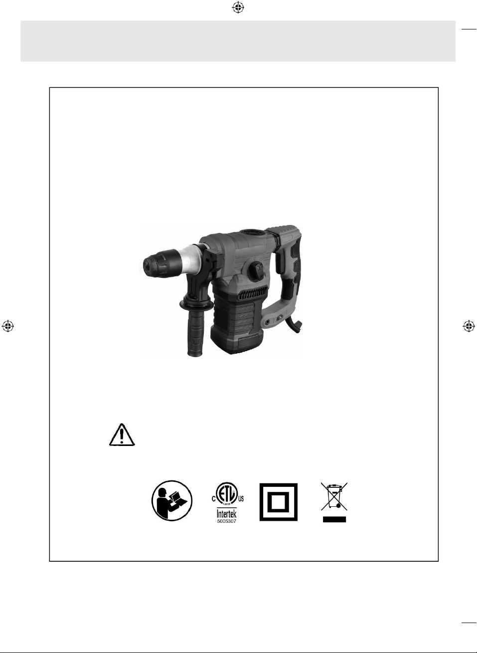
ROTARY HAMMER
WARNING:To reduce risk of injury ,user must
read and understand instruction mamual.
WARNING : Cancer and Reproductive Harm
-www.P65Warnings.ca.gov.
2
2
3
3

4
4
Table of contents
1.
Introduction
...................................................................................................
06
Symbols used
.................................................................................................................................
06
Scope of delivery / parts list
.........................................................................................................
06
2.
Safety
.........................................................................................................
07
Proper use
..............................................................................................................................................
07
Residual risks
.........................................................................................................................................
07
General safety instructions for power tools
................................................................................................
07
Safety instructions for hammers
..................................................................................................................
10
Additional safety instructions for hammers
................................................................................................
10
3.
Before Use
......................................................................................................
10
Checking the drill and pack contents
...................................................................................................
10
Mounting the additional handle (Fig. A)
.............................................................................................
10
Inserting the tools (Fig. B, C)
................................................................................................................
10
Mounting the depth stop (Fig. D)
........................................................................................................
11
4.
Usage
.........................................................................................................
11
Mains connection
..................................................................................................................................
11
Switching on and off (Fig. E)
.................................................................................................................
11
Speed adjustment (Fig. F)
.....................................................................................................................
11
LED display
.....................................................................................................................................
11
Function selection (Fig. G)
............................................................................................................
12
Drilling and chiselling
....................................................................................................................
12
5.
Maintenance, cleaning, storage and transport
..........................................
13
Maintenance
................................................................................................................................
13
Cleaning
.........................................................................................................................................
13
Storage
..........................................................................................................................................
13
Transport
.......................................................................................................................................
13
6.
Troubleshooting
............................................................................................
14
7.
Technical data
.....................................................................................................
14
8.
Noise and vibrations levels
..........................................................................
15
9.
Recycling
........................................................................................................
15
Disposal of packaging
....................................................................................................................
15
Disposing of the drill
.............................................................................................................................
15
5
5
NOTE!
1.
Introduction
Congratulations on the purchase of your new
product. You have chosen a high quality quality
product with this purchase. These operating
instructions form an integral part of this Hammer
Drill (hereafter referred to only as the „drill“).
It contains important instructions on safety, use
and disposal of the product. Please familiarise
yourself with all operating and safety instructions
before using the product. Only use the product
as described and for the stated purpose. If the
product is passed on to a third party, please
provide all documents to the third party together
with the product.
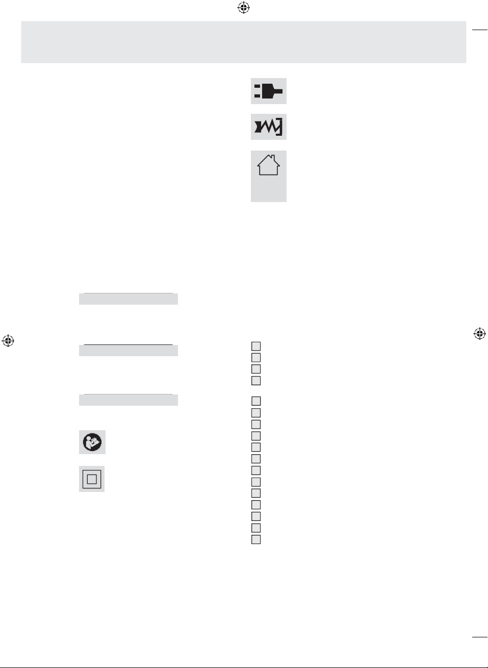
Symbols used
The following symbols and key words are used in
this operating manual, on the hammer drill or on
the packaging.
Mains plug is inserted (green
indicator).
Carbon brushes worn out (red
indicator).
The hammer drill is intended for use
only in places that have a
continuous current rating of ≥ 100 A
per phase and are supplied with a
rated voltage of 120 V by the
distribution network.
WARNING!
Indicates a hazard that, if not avoided, could
result in death or serious injury.
CAUTION!
Signals a hazard that can cause injuries when
ignored.
Warns against possible damages.
Read the operating manual.
Protection category 2
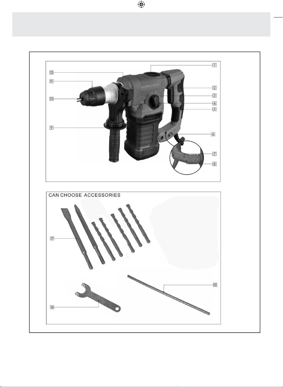
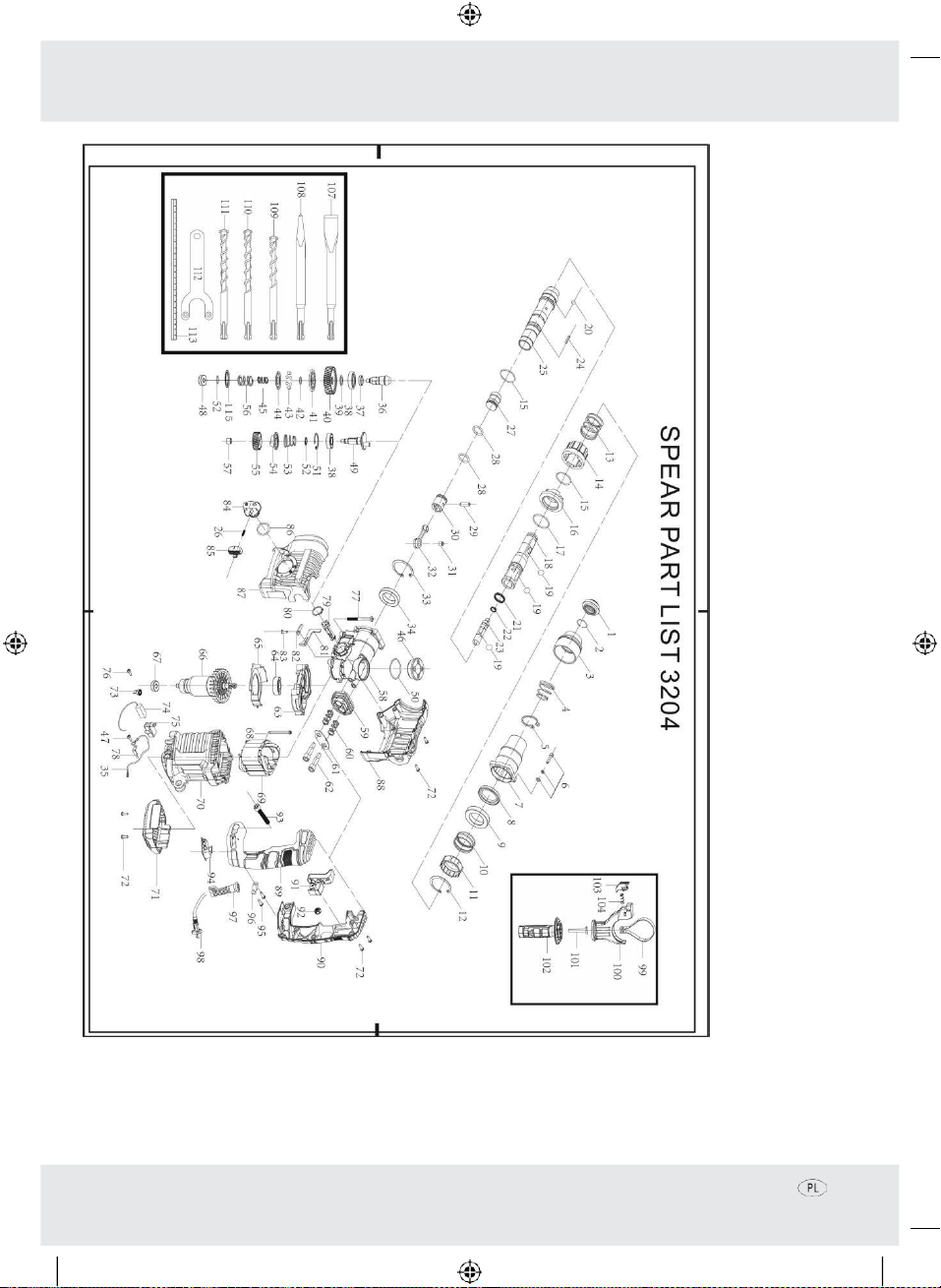
Scope of delivery / parts list
Housing cover for lubrication
ON / OFF Switch
Function selector switch
Unlocking mechanism for drilling / hammer
drilling / chiselling
Anti- vibration handle
Speed control
GREEN LED Indicator
RED LED indicator
Additional handle
Tool holder
Locking sleeve
Depth stop locking latch
Depth stop
Key for lubrication of the housing cover
Accessories (suitable for use with SDS+
system)
-
1 pointed chisel
-
1 flat chisel
-
3 drill bits (6.8, 10,12 & 14 mm)
1
2
3
4
5
6
7
8
9
10
11
12
13
14
15
16
17
≥ 100A

6
6
WARNING!
2.
Safety
Proper use
This drill is exclusively designed for private use
and for hobby and DIY projects for the following
purposes:
Drilling:
-
Drilling metal, wood and plastic.
Hammer drilling:
-
Drilling concrete, stone, granite, brickwork and
similar materials.
Chiselling:
-
Chiselling brickwork and masonry.
The hammer drill has to be used properly as
specified. Any other use is forbidden. The
manufacturer cannot be held responsible for
damage or injury caused by use the machine for
other than its intended purpose.
Only accessories which are suitable for the drill
may be used. Non-observance of the safety,
assembly and operating instructions while
operating the appliance counts as misuse.
Anyone who operates or services the drill must be
familiar with these instructions and must be aware
of possible dangers. Any applicable health and
safety regulations must also be followed.
Any other applicable local and national
legislation must also be followed. The drill may
not be modified. The manufacturer can accept
no responsibility for damage or injury caused by
modifications to the drill.
The drill has not been designed for professional,
trade or industrial use, but for private users in the
hobby and DIY sector.
Any other use of the product is expressly
forbidden and is considered as misuse.
Residual risks
Residual risks cannot be completely ruled out
even in case of proper use. Due to the nature of
the drill, the following dangers may arise:
-
Burns from coming into contact with hot parts
of the hammer drill or workpiece.
-
Harmful emissions of dust in poorly ventilated
spaces or inadequate extraction in closed
rooms.
-
Injury and property damage caused by parts
flung out or tool attachment breakage.
General safety instructions for
power tools
Read all
safety
information,
instructions,
illustrations
and
technical
data
supplied
with
the electric
power
tool.
FAILURE
to
follow
these
INSTRUCTIONS
may
RESULT
in electric shock,
fire
and/or
SERIOUS
INJURIES.
Retain all the warnings and
safety instructions for future
reference.
The
term
„power
tool“
in
the
safety
INSTRUCTIONS
refers
to
YOUR
mains-
operated
(with
power
cord)
power
tool
or
battery-operated
(WITHOUT
power
cord)
power
tool.
1)
Work area safety
a)
Keep your work area clean
and well lit. Disorderly or
INADEQUATELY
lit work areas can
lead to accidents.
b)
Do not work with the power
tool in potentially explosive
atmospheres containing
flammable liquids, gases
or
dusts.
Power tools
generate
sparks
which
may ignite
the DUST
or
FUMES.
c)
Keep children and other
people out of the area when
operating the power tool.
Distractions can
CAUSE YOU
to lose
control of the power tool.
2)
Electrical safety
a)
The power tool‘s mains plug
has to fit the socket. The plug
should not be modified in any
way. Do not use any adapter
plugs with the earthed

7
7
(grounded)
power
tools.
Unmodified
PLUGS
and
matching
sockets
will
REDUCE
risk
of
electric
shock.
b)
Avoid bodily contact with
earthed objects such as
pipes, radiators, ovens and
refrigerators. There is an
increased risk ofelectric shock if
YOUR
body
is
earthed
or
GROUNDED
.
c)
Keep power tools out of rain
and wet environments.
Water
entering a power tool will increase
the risk of electric shock.
d)
Do not use the power cord for
purposes for which it is not
intended, such as carrying
or hanging up the power tool,
and do not pull the cord to
disconnect the tool from the
mains. Keep the power cord
away from heat, oil, sharp
edges or moving parts.
Damaged or entangled power
cords increase the risk of electric
shock.
e)
When operating the power
tool outdoors, use only
extension cords suitable for
outdoor use.
Using an extension
cord SUITABLE for OUTDOOR USE
REDUCES
the risk of electric shock.
f)
If you need to use the power
tool in a damp environment,
use a residual current
protection device.
Using a
RESIDUAL CURRENT protection device
REDUCES
the risk of electric shock.
3) Personal safety
a)
Stay alert, watch what you
are doing and use common
sense when operating a
power tool. Do not use a
power
tool
while
you are
tired
or
under
the influence
of
drugs,
alcohol
or
medication.
A
moment
of
inattention
while
operating
power
tools may
RESULT
in
SERIOUS
INJURY.
b)
Wear personal protective
equipment and always use
safety goggles.
Protective
EQUIPMENT SUCH
as
DUST
mask,
non-skid safety shoes, hard hat,
or hearing protection
USED
for
appropriate
conditions
will
REDUCE
personal
INJURIES.
c)
Prevent unintentional start-up.
Ensure that the switch is in the
off-position before connecting
to the power source and/
or battery pack, picking up
or carrying the tool. Carrying
power
tools
with
YOUR
finger on
the
switch
or
connecting
it
to the
mains
with
the switch
in
on-position,
may
RESULT
in accidents.
d)
Remove any adjusting tools
or keys before you switch the
power tool on.
A tool or a key
left in a rotating part of the power
tool may
RESULT
in
INJURIES
.
e)
Avoid working with your
body in an unusual position.
Ensure proper footing and
balance at all times.
This
enables better control of the power
tool in
UNEXPECTED SITUATIONS
.
f)
Wear sensible clothing. Do
not wear loose clothing or
jewellery. Keep your hair and
clothing away from moving
parts.
Loose clothes, jewellery or
long hair can be
CAUGHT
in moving
parts.

8
8
g)
If dust extraction and
collection units can be
installed, they have to be
connected and used properly.
Use of DUST collector can REDUCE
DUST-RELATED hazards.
h)
Never assume that you are
safe enough and disregard
the safety rules for electric
power tools, even if you
are familiar with the electric
power
tool
after
using
it
many
times.
Carelessness
may
lead
to
SERIOUS
INJURY
within
a
fraction
of
a
second.
4) Power tool use and care
a)
Do not overload the power tool.
Use power tools that are
intended for your work.
The
correct power tool will do the job
better and safer at the rate for
which it was designed.
b)
Do not use the power tool if
the switch is faulty.
A power
tool which can no longer be
switched onand off is
DANGEROUS
and has to be repaired.
c)
Disconnect the plug from the
socket and/or remove the
battery before making any
adjustments, changing tool
bits or accessories or putting
the power tool away. SUCH
preventive safety
MEASURES REDUCE
the risk of starting the power tool
accidentally.
d)
Store power tools out of the
reach of children when not
in use. Do not allow persons
unfamiliar with the power
tool or these instructions, to
operate the power tool. Power
tools
are
DANGEROUS
in
the
hands of
inexperienced
USERS.
e)
Maintain the power tools and
tool bits carefully. Ensure the
moving parts are functioning
correctly and do not getting
stuck. Check if parts are
broken or so badly damaged
that that the power tool‘s
functions are impaired. Get
damaged parts repaired
before using the power tool.
Many accidents are CAUSED by
poorlymaintained powertools.
f)
Keep cutting tools sharp and
clean. Properly maintained tools
with sharp CUTTING edges are less
likely to get STUCK and are easier to
control.
g)
Use your power tool,
accessories and bits
etc. according to these
instructions. Consider your
working environment and the
type of job you wish to do.
Using power
tools
for applications
other
than those
intended can
lead
to
DANGEROUS
SITUATIONS
.
h)
Keep the handles and
gripping surfaces dry, clean
and free of oil and grease.
Slippery handles and gripping
SURFACES
preventsafeoperation
and control of the power tool in
UNEXPECTED SITUATIONS
.
.
09
9
9
9
WARNING!
NOTE!
Safety instructions for hammers
1)
Wear ear protection.
Noise can
CAUSE
loss of hearing.
2)
Use the auxiliary handles
supplied with the machine
Loss
of control over the machine can
lead to
INJURY
.
3)
Hold the tool by its insulated
gripping surfaces only when
performing an operation
where the drill bit may contact
hidden wiring or its own cord.
CUTTING accessory contacting a
„live“ wire may make exposed
metal parts of the power tool
„live“ and shock the operator.
Additional safety instructions for
hammers
1) Wear a suitable dust mask.
2) Massive torque can be
exerted on the drill bit at hole
breakthrough and especially
3.
Before Use
Disconnect the machine from the
mains before performing any
maintenance or adjustments.
Checking the drill and pack
contents
•
Take the drill and accessories out of the
packaging.
•
Check if the delivery is complete (see section
“SCOPE OF DELIVERY / DESCRIPTION OF
PARTS”).
•
Check if the drill or the accessories are
damaged.
•
Do not use the drill if it is damaged or parts
are missing. Contact the manufacturer via the
service centre.
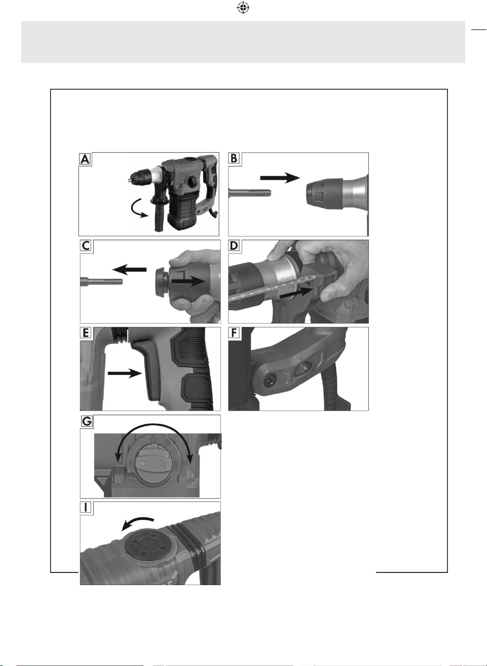
Mounting the additional handle
(Fig. A)
WARNING!
Only use the drill with the additional
handle. The additional handle gives
if the
drill
bit
jams
or seizes
in
the
hole.
Always
grip
the
machine
with
two
hands
and
to
maintain
a
SECURE
stance.
3) Consider the possibility that
the bit could snap or that the
workpiece could slip or move
suddenly; adopt a stance such
that it does not lead to injury.
4)
Dill bits become extremely
hot during operation.
Avoid
TOUCHING the bit and make SURE that
the drill is left in a safe place after
finishing work.
5) Ensure that there are no
power lines, water pipes or
waste pipes under the surface
before drilling a wall, floor or
ceiling.
YOU
more control when
GUIDING
the
drill.
•
Slide the additional handle with the round
opening over the chuck on the clamping neck
of the hammer drill.
•
Position the handle by rotating it around the
clamping neck, so you can work comfortably.
•
Tighten the additional handle by rotating
the lower part of the handle in clockwise
direction.
•
To loosen the additional handle again, or to
change the position, proceed in reverse order.
Inserting the tools (Fig. B, C)
Ensure that the tool shaft and the
tool holder are free from dust and
lightly grease the shaft before
inserting it into the chuck. This
extends the lifetime of the chuck
and the machine.
10

10
10
Mounting the depth stop (Fig. D)
•
Press and hold the depth stop locking latch 1 2
on the additional handle 9
•
Insert the depth stop 15 into the hexagonal opening provided on the additional handle above the locking
latch.
•
Push the depth stop in the direction of the hammer drill till the desired depth is reached.
•
Release the locking latch of the depth stop.
•
Check the locking mechanism by gently pulling the inserted depth stop.
•
To readjust the depth stop or to remove it,proceed in same order.
4.
Usage
Mains connection
The hammer drill is designed for use with single- phase AC 120 V
~
/
60 Hz and has protective
insulation. Check whether the mains voltage of
the socket corresponds with the mains voltage indicated on the drill’s rating label. Use an extension cable if the
work area is not close to the mains outlet. Ensure an extension cable with sufficient conductor diameter (min.
1.5 mm²) is used. If necessary, ask the dealer for advice when purchasing. The extension cable used should be as
short as possible. Ensure the mains cable does not pose a tripping hazard.
Mains cables may only be replaced by the manufacturer, an authorised service centre or a qualified person.
11
11
The hammer drill is intended for use only in places that have a continuous current rating of ≥ 100 A per phase
and are supplied with a rated voltage of 120V by the distribution network. If necessary, please consult your
electricity supplier to ensure that the continuous current rating of the network is adequate for connecting the
hammer drill at the point where it is connected to the power supply network.
Switching on and off (Fig. E)
Switching on:
•
Press the On/Off switch 2 .
Switching off:
•
Release the On/ Off switch.
Speed adjustment (Fig. F)
•
The speed can be adjusted using the speed regulator
6
according to the requirements. This can be done
when the machine is being operated, with 1 being the lowest and 6 being the highest speed.
LED display
The hammer drill is provided with an LED status indicator at the bottom of the vibration-proof handle
5
.
The two LEDs indicate the following status:
-
If the power cord is inserted, the GREEN LED indicator starts to glow 7 . The hammer drill isready for use
-
If the carbon brushes are qorn out, the RED LED indicator starts to glow
8
. Stop the workand contact the
manufacturer‘s customer service department.
11
12
12
NOTE!
Function selection (Fig. G)
The selector switch should only be
used when the motor has stopped
completely.
Never work with chisel in inserted
(hammer) drilling position or
with the drill inserted in the chisel
position.
•
Unlock the function selector switc 3using the
unlocking latch 4and hold it pressed.
•
Turn the function selector switch so that the
arrow marking points at the desired operation
symbol.
- Drilling. For drilling wood, steel and
similar materials.
-
Hammer drilling. For hammer drilling of
concrete, granite and similar materials.
-
Rotation stop. Adjusting the chisel
position. For continuous adjustment of
the axis. Then rotate the function selector
switch back to the Chiselling position.
-
Chiselling. For light chiselling or chipping.
•
Release the unlock latch.
•
Check if the function selector switch is locked in
place by trying to rotate it without pressing the
unlocking latch.
Drilling and chiselling
Drilling
•
Choose a drill bit appropriate for the
application and insert it into the tool as
described in chapter ‚Inserting the tools‘.
•
Insert the drill bit properly at the desired
location.
•
Press the On / Off switch 2 to start drilling.
.
Do
not
apply
excessive
force on
the
hammer drill.
Excessive
PRESSURE
may
damage
the
drill,
chisel
or
the hammer
drill and
increases
the
risk
of accident.
For
this
reason
is
it
important
to
always
grip
the
drill
firmly
with
two hands
and
maintain
a
stable
posture.
The
greater
the
diameter
of
the
drill
bit,
the
greater
is the
force on YOUR
arm.
Always secure your workpiece
in a vice or in any other clamping
device. Secure particularly large
workpieces against sliding or
support them properly.
Selecting the appropriate drill bit
For drilling concrete Carbide tipped masonry
and stone: drill bit
For Metal HSS drill bit
For wood Twist drill bits for wood
12
WARNING!
13
13
WARNING!
CAUTION!
Chiselling
•
Choose a chisel appropriate for the material
and insert it into the tool as described in chapter
‚Fitting and changing tools‘.
•
Position the the chisel using the rotation stop
position if necessary as described in „Function
selection“ .
•
Insert the chisel properly at the desired location.
•
Press the On / Off switch
2
to start chiselling.
5.
Maintenance, cleaning,
storage and transport
Disconnect the machine from the
mains before performing any
maintenance or adjustments
.
Maintenance
The hammer drill is practically maintenance-free.
Only use spare parts / accessories from the
manufacturer or authorised and qualified
workshops.
Repairs should only be carried out by qualified
technicians or by an authorised service centre.
Qualified technicians must have relevant training
and experience, be familiar with the design and
construction requirements of the product and
understand and follow the safety regulations.
Keep your tool bits always sharp. Sharpen them
always using a suitable tool as recommended by
the tool bit manufacturer.
Refilling the lubricating grease (Fig. I)
In order to avoid ingression of dust and leakage
of grease, the pneumatic part of the hammer drill
is sealed. Refill grease after 50 operating hours
or when the impact power decreases.
•
Open the housing cover for lubrication 1 using
the supplied spanner
16
.
•
Refill with the supplied grease and close the
cover in reverse order. Refill with gear grease
for central lubrication.
•
Spray a small amount of MOS2 oil into the tool
holder if you do not intend to use the drill for a
longer period of time. This prevents the impact
piston from seizing.
Replacing the carbon brushes
The carbon brushes may only be replaced by an
authorised specialist workshop or by qualified
skilled personnel.
Replacing the mains cable
Damaged mains cables may only be replaced
with genuine replacement cables available from
the manufacturer.
The power cord should only be replaced by an
authorised specialist workshop or by qualified
skilled personnel.
Cleaning
Make sure that liquids do not get
inside the hammer drill.
•
Clean the hammer drill regularly with a dry
cloth. Never use strong and / or abrasive
cleaning agents or solvents. Allow all the parts
to dry completely.
•
Ensure that the ventilation slots are not blocked
and clean the housing of the hammer drill
regularly with a soft cloth.
Storage
•
Clean the hammer drill before storage.
•
Keep the hammer drill in a safe, cool, dry
and well-ventilated place, out of the reach of
children when not in use.
•
Store the hammer drill at an ambient
temperature of 0
-
40
°
C.
Transport
•
Use the original packaging and secure the
hammer drill in place during transport.
•
Always carry the hammer drill using the
handle provided for this purpose.
13
14
14
6.
Troubleshooting
Problem Possible cause Rectification
The drill does not start. Damaged cable. Have the cable replaced by a service center.
Fuse tripped. Check the household fuse box
Carbon brushes worn out. Have the carbon brushes checked by customer
service
Trigger defective Have the trigger switch checked by customer
service
Poor drilling
performance.
Drill bit is blunt. Sharpen or replace the drill bit.
Chuck turns or does
not turn.
Hammer mode on
or off
Function selector switch in
the wrong position.
Function selector switch in
the wrong position.
Check if the function selector switch is inthe
position suitable for your application.
Check if the function selector switch is inthe
position suitable for your application.
7.
Technical data
Model No.: ZSRH-009
Mainsconnection 120 V
~
/ 6
0 Hz
Rated power 12.5 A
No-load speed 0 - 800 rpm
Max. Impact Rate: 0 - 39000 bpm
Impact energy 5.0 Joule
Chuck Chuck suitable for use with SDS+ system
Keyed chuck 1.5 -13 mm
Max drilling capacity 32 mm (concrete)
32 mm (brickwork)
13 mm (steel)
40 mm (wood)
Protection class II
14
04.04.2019 16:53:20
15
15
8.
Noise and vibrations
levels
Noise emission levels
Tested according to EN 60745. The noise level
at the workplace may exceed 80 dB (A); safety
precautions are required for the operator in this
case (wear suitable hearing protection device).
Sound pressure level Impact drilling: L
pA
93.2 dB(A)
Sound pressure level Chiselling: L
pA
82.6 dB(A)
Sound power level Impact drilling: L
wA
104.2 dB(A)
Sound power level Chiselling: L
wA
93.6 dB(A)
Uncertainty: K
pA /
K
wA
3 dB
Vibration details
Hammer drilling: a
h,HD
17.353 m/s
2
(vibration-proof handle)
11.585 m/s
2
(additional handle)
Chiselling: a
h,CHeq
15.692 m/s
2
(vibration-proof handle)
11.767 m/s
2
(additional handle)
Uncertainty: K
1.5 m/s
2
CAUTION:
The overall vibration values and the noise
emission values specified have been measured
according to a standardized test method and can
be used to compare one power tool with another.
The overall vibration values and the noise
emission values specified can also be used for a
preliminary estimation of the load.
WARNING!
The vibration and noise emissions during the
actual use of the power tool may differ from the
specified values, depending on the manner in
which the power tool is used, especially, the type
of workpiece being machined
Safety measures may be required to protect the
operator that are based on an estimate of the
vibration load during actual usage conditions (in
this case all the parts of the operating cycle have
to be considered, such as times when the power
tool is turned off, and those where, the tool is
turned on, but is running without load).
9.
Recycling
Disposal of packaging
Dispose of packaging separately. Dispose
of card and paper in waste paper, plastic
at collection points.
Disposing of the drill
This symbol indicates that this product
may not be disposed of together with
domestic waste in compliance with the
(2012/19/EC) directive pertaining to
waste electrical and electronic devices (WEEE).
This product must be handed in at an designated
collection point. This can occur, for example, by
returning it when a similar product is purchased
or by handing it in at an authorised collecting
point for the recycling of waste electrical and
electronic equipment. Owing to potentially
hazardous substances that are frequently
contained in waste electronic equipment,
incorrect handling of waste equipment may have
a negative impact on the environment and on the
health of human beings. By disposing of this
product correctly, you are also contributing
towards an efficient use of natural resources.
Information on collecting points for waste
equipment can be obtained from your local
authority, the public waste disposal authority, an
authorised institution for the disposal of waste
electrical and electronic equipment or the waste
collection services. Dispose of device and
packaging in an environmentally friendly manner.
.
15
instructions provided in the operating manual
04.04.2019 16:53:25
16
16
04.04.2019 16:53:25
17
17
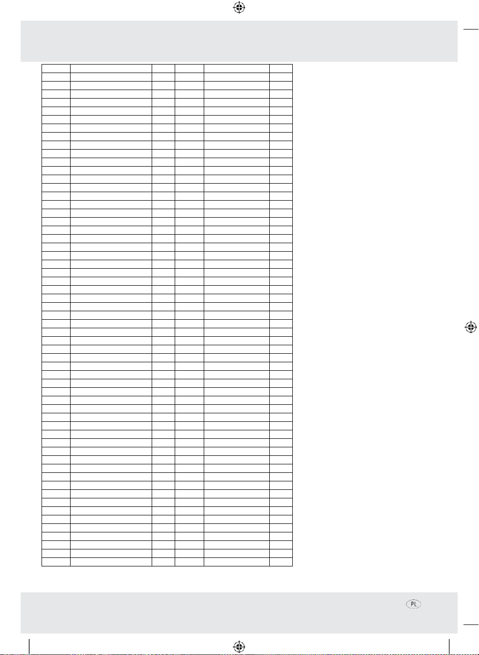
No.
NAME
QTY
No.
NAME
QTY
1
front cap
1
59
damping set
1
2
steel check ring
1
60
spring
2
3
bit lock set
1
61
damping board
2
4
spring
1
62
damping screw
1
5
circlip 30
1
63
middle cover
1
6
screw
4
64
bearing 6001
1
7
cylinder house
1
65
lead wind ring
1
8
oil seal
1
66
rotor
1
9
bearing906
1
67
bearing 608
1
10
spring
1
68
screw
2
11
lock steeve
1
69
stator
1
12
circlip
1
70
motor house
1
13
cluth spring
1
71
bottom cover
1
14
cluth
1
72
screw 16
14
15
steel check ring
1
73
screw6
3
16
gear 34
1
74
coil spring
2
17
o-ring 28*1.8
1
75
brush
2
18
cylinder
1
76
brush holder
2
19
steel ball 5.5
3
77
screw
4
20
steel ball 7.14
3
78
function axle
1
21
X-ring22.5
1
79
fork
1
22
x-ring13
1
80
steel check ring22
1
23
punch hammer
1
81
fork
1
24
pin
2
82
hold fork
1
25
telefiex
1
83
screw 6
1
26
steel check ring
1
84
function switch
1
27
hammer
1
85
konb lock
1
28
0-ring 19
2
86
spring
1
29
piston pin
1
87
gear box cover
1
30
pison
1
88
gear box cover
1
31
connecting rod bearing
1
89
handle
1
32
connecting rod
90
handle
1
33
steel check ring47
1
91
switch
1
34
oil bearing 30*47*9
1
92
screw 8
1
35
line
1
93
screw 40
1
36
gear
1
94
speed switch
1
37
adjusting washer
1
95
screw
2
38
bearing 6002
1
96
electric cable
1
39
adjusting washer
2
97
cable sheath
1
40
gear 39
1
98
cable
1
41
hold board
1
99
hoop
1
42
steel check ring12.5
1
100
bracket
1
43
steel ball 5
8
101
T-screw
1
44
move board
1
102
hand shank
1
45
spring
1
103
ruler knob
1
46
oil cover
104
spring
1
47
screw
2
105
1
48
bearing 627
106
1
49
eccentric shaft
1
107
flat chisel
1
50
o-ring
1
108
point chisel
1
51
steel check ring32
1
109
drill 12x150mm
1
52
steel check ring15
110
drill 10x150mm
1
53
spring
1
111
Drill8x150mm
1
54
cluth
1
112
oil cover key
1
55
gear
1
113
rule
1
56
steel check ring8.8
1
114
1
57
bearing
1
115
spring washer
1
58
gear house
1