Loading ...
Loading ...
Loading ...
To Square Blade to Fence (Fig. P):
1. Turn the upper arm assemblyto the 0° bevel
position and lock in position.
2. Using a hex keywrench, loosen the four fence
locking hex socket bolts (1) untilthe fence (2) is
loose.
3. Lower the cutting head assembly and lock it in the
down position withthe stop pin.
4. Using a combination square (3), lay the heel of the
square against the blade, and the rule against the
fence (2) as shown. Check to see if the fence is
90° to the blade.
5. If an adjustment is necessary, shift the fence until it
is square to the blade. _ghten the four fence
locking bolts (1) once alignment is achieved.
CAUTION: If the saw has not been used recently,
recheck blade squareness to the fence and
readjust if needed.
To avoid injury:
Form unexpected starting or electrical shock, do not
plug the saw in. The power cord MUST remain
unplugged when you are working on the saw.
Fig. P
5 4 1
Positive Stop Miter Angle Adjustment: (Fig. Q)
1. Unlock the miter table by lifting up on the miter
quick-cam table lock (3).
2. While raising the positive stop locking lever up (2),
grasp the miter handle and rotate the miter table left
or right to the desired angle.
3. Release the positive stop locking lever and set the
miter at the desired angle making sure the lever
snaps into place. NOTE: The lever will only lock
into place at one of the ten positive stops.
4. Once angle is achieved, press down on the
quick-cam miter table lock (3- Fig. (3).
Quick-Cam Miter Table Lock Operation: (Fig. Q)
If miter angles required are NOT one of the ten positive
stops noted above, the mitertable can be locked at any
angle between these positive stops I_yusing the Miter
Quick-Cam table lock.
1. Unlock the miter table by lifting up on the miter
quick-cam table lock (3).
2. While holding the positive stop locking lever up (2),
grasp the miter handle and move the miter table left
or right to the desired angle.
3. Release the positive stop locking lever..
4. Press down on the Miter Quick-Cam locking lever
(3) until it locks the miter table in place.
NOTE: The miter Quick-Cam locking lever should
lock the table and prevent it from moving. If
adjustment is needed, see next step.
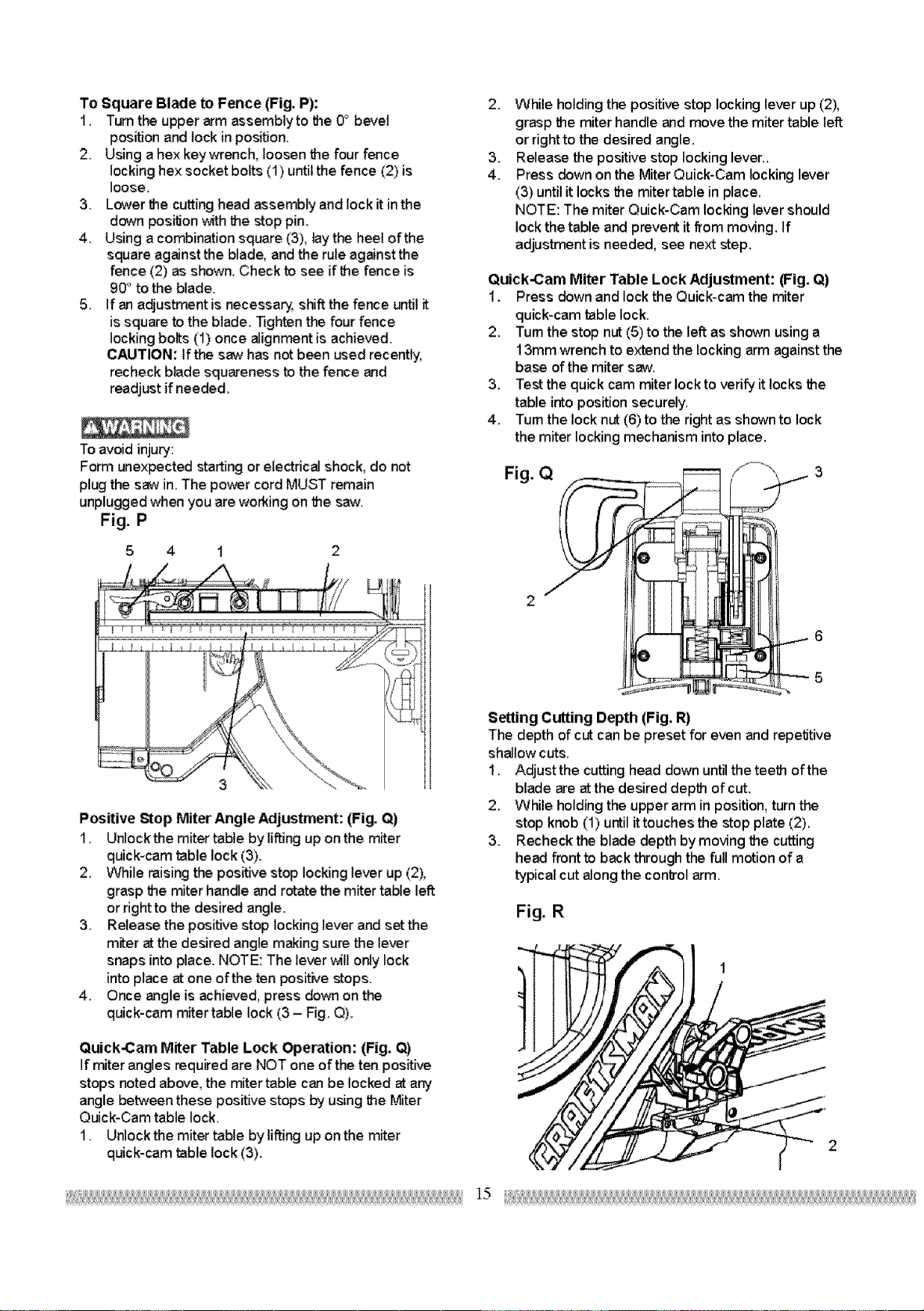
Quick-Cam Miter Table Lock Adjustment: (Fig. Q)
1. Press down and lock the Quick-cam the miter
quick-cam table lock.
2. Turn the stop nut (5) to the left as shown using a
13ram wrench to extend the locking arm against the
base of the miter saw.
3. Test the quick cam miter lock to verify it locks the
table into position securely.
4. Turn the lock nut (6) to the right as shown to lock
the miter locking mechanism into place.
Fig. Q
2
Setting Cutting Depth (Fig. R)
The depth of cut can be preset for even and repetitive
shallow cuts.
1. Adjustthe cutting head down until the teeth of the
blade are at the desired depth of cut.
2. While holding the upper arm in position, turn the
stop knob (1) until it touches the stop plate (2).
3. Recheck the blade depth by moving the cutting
head front to back through the full motion of a
typical cut along the conb'ol arm.
Fig. R
Loading ...
Loading ...
Loading ...