Loading ...
Loading ...
Loading ...
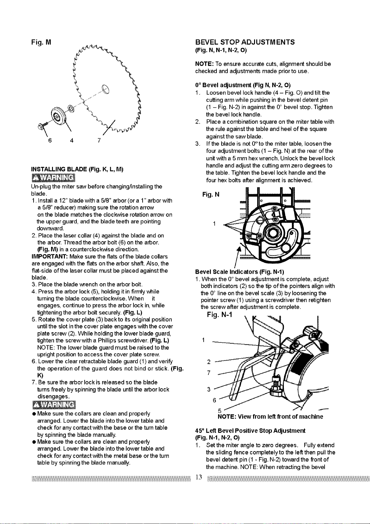
Fig. M BEVEL STOP ADJUSTM ENTS
(Fig. N, N-l, N-2, O)
NOTE: To ensure accurate cuts, alignment should be
checked and adjustments made prior to use.
6 4 7
INSTALLING BLADE (Fig. K, L, M)
Un-plug the miter saw before changing/installing the
blade,
1. Install a 12" blade with a 5f8" arbor (or a 1" arbor with
a 5/8" reducer) making sure the rotation arrow
on the blade matches the clockwise rotation arrow on
the upper guard, and the blade teeth are pointing
downward.
2. Place the laser collar (4) against the blade and on
the arbor. Thread the arbor bolt (6) on the arbor.
(Fig. M) in a counterclockwise direction.
IMPORTANT: Make sure the flats of the blade collars
are engaged with the fiats on the arbor shaft. Also, the
flat-side of the laser collar must be placed against the
blade.
3. Place the blade wrench on the arbor bolt.
4. Press the arbor lock (5t, holding it in firmly while
turning the blade counterclockwise. When it
engages, continue to press the arbor lock in, while
tightening the arbor bolt securely, (Fig. L)
5. Rotate the cover plate (3) backto its original position
until the slot in the cover plate engages with the cover
plate screw (21. While holding the lower blade guard,
tighten the screw with a Phillips screwdriver. (Fig. L)
NOTE: The lower blade guard must be raised to the
upright position to access the cover plate screw.
6. Lower the clear retractable blade guard (1) and verify
the operation of the guard does not bind or stick. (Fig.
K)
7. Be sure the arbor lock is released so the blade
turns freely by spinning the blade until the arbor lock
disengages,
0° Bevel adjustment (Fig N, N-2, O)
1, Loosen bevel lock handle (4- Fig. O) and tilt the
cutting arm while pushing inthe bevel detent pin
(1 - Fig. N-21 in against the 0° bevel stop. Tighten
the bevel lock handle.
2. Place a combination square on the miter table with
the rule against the table and heel of the square
against the saw blade.
3, If the blade is not 0° to the miter table, loosen the
four adjustment bolts (1 - Fig. N) at the rear of the
unitwith a 5 mm hex wrench. Unlock the bevel lock
handle and adjust the cutting arm zero degrees to
the table. Tighten the bevel lock handle and the
four he× bolts after alignment is achieved.
Fig. N
Bevel Scale Indicators (Fig. N-l)
1. When the 0° bevel adjustment is complete, adjust
both indicators (2) so the tip of the pointers align with
the 0° line onthe bevel scale (3) by loosening the
pointer screw (11 using a screwdriver then retighten
the screw after adjustment is complete.
Fig. N-1
2
7
3
6
• Make sure the collars are clean and properly
arranged. Lower the blade into the lower table and
check for any contact with the base or the turn table
by spinning the blade manually.
• Make sure the collars are clean and properly
arranged. Lover the blade into the lower table and
check for any contact with the metal base or the turn
table by spinning the blade manually.
5
NOTE: View from leftfront of machine
45 ° Left Bevel Positive Stop Adjustment
(Fig. N-l, N-2, O)
1. Set the miter angle to zero degrees. Fully extend
the sliding fence completely to the left then pull the
bevel detent pin (1 - Fig. N-2t toward the front of
the machine, NOTE: When retracting the bevel
Loading ...
Loading ...
Loading ...