Loading ...
Loading ...
Loading ...
WARNING – SERVICING TO BE CARRIED OUT ONLY BY AN AUTHORISED PERSON
Disconnect from electricity and gas before servicing. Check appliance is safe when you have nished.
40
ArtNo.322-0002 Oven bottom element access
A
BB
2. To Replace the Oven Multi-function Switch
DISCONNECT FROM THE ELECTRICITY SUPPLY.
Move the cooker away from the wall to allow access to the
rear.
Remove the control panel (see 1. To Remove the Control
Panel) and hotplate (see 1. To Remove the Hotplate).
Remove the xing screws from the front of the oven multi-
function switch. Disconnect the leads and remove the switch.
Fit the new switch.
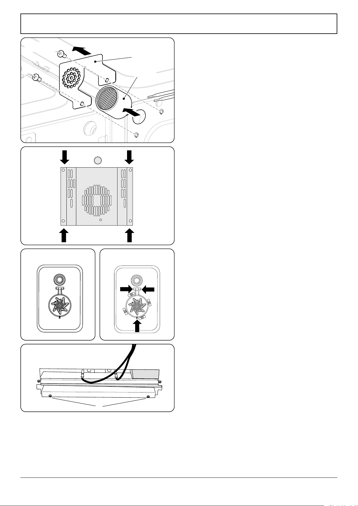
3. To Replace the Oven Catalytic Converter
DISCONNECT FROM THE ELECTRICITY SUPPLY.
Undo the 2 screws holding the catalytic lter cover in place
(Fig. 11.7) and remove.
Pull out the catalytic assembly.
Replace the catalyst and t in reverse, making sure that the
cover ts over the ends of the thermostat phials.
4. To Remove an Oven Inner Back Panel
DISCONNECT FROM THE ELECTRICITY SUPPLY.
Open the oven door. For the right-hand side unscrew the 4
thermostat phial xing screws.
Remove the xings that secure the inner back to the oven
rear (Fig. 11.8). Lift the removable panels away.
Reassemble in reverse order. Make sure that the retaining
xings are fully tightened.
5. Replacing an Oven Fan
DISCONNECT FROM THE ELECTRICITY SUPPLY.
Pull the cooker forward to access the cover boxes at the rear
of the cooker.
Remove the inner back panel (see 4. To Remove an Oven
Inner Back Panel).
Hold the fan blades and undo the centre nut (Left-hand
thread), brass washers, fan blade and circlip (Fig. 11.9). Undo
the screws that retain the fan and remove it from the cavity
rear.
Fit the replacement and reassemble the parts in reverse order.
Check that the oven operates satisfactorily.
6. Replacing an Oven Fan Element
DISCONNECT FROM THE ELECTRICITY SUPPLY.
Remove the inner back panel (see 4. To Remove an Oven
Inner Back Panel).
Remove the screws that secure the element within the oven
and carefully lift the element away (Fig. 11.10).
Disconnect the leads and connect to the replacement
element and reassemble the parts in reverse order.
ArtNo.281-0148
- USA Oven Fan
ArtNo281-0148USAOvenFan
ArtNo.281-0149 - Fan oven inner
ArtNo.281-0149 - Fan oven inner
Catalytic
assembly
Filter cover
Fig. 11.7
Fig. 11.8
Fig. 11.9 Fig. 11.10
Fig. 11.11
Loading ...
Loading ...
Loading ...