Loading ...
Loading ...
Loading ...
38
1
1
1
1
1
1
1
1
1
a
b
e
f
c
d
1
2
1
1
1
&
X
X
X
C
C
C
C
C
C
CC
C
C
C
C
C
CC
CC
PS
PS
PS
PS
HS
CL
X
Z
Z
Z
W
W
W
W
W
W
CL
CL
S
SS
S
CS
CS
S
C
S
HS
X
Z
S
CS
CS
CS
CS
CSCS
CS
X
W
WC
X
X
X
X
C
C
C
CS
C
C
C
X
CS
C
C
X
CL
CL
CCCS CS C C CCS
S
S
W
W
"
"
#
#
#
#
#
#
#
$
%
%
%
%
'
'
(
(
)
)
*
*
*
+
+
+
*
"
A
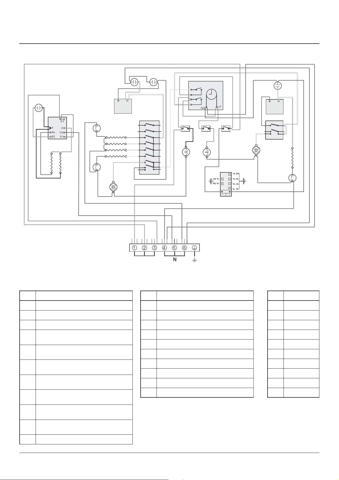
Key
The connections shown in the circuit diagram are for single-phase. The ratings are for 230 V 50 Hz.
Code Colour
b Blue
br Brown
bk Black
or Orange
r Red
v Violet
w White
y Yellow
g/y Green/yellow
gr Grey
11. Circuit Diagram
Code
Description
A1
Grill control
A2
Left-hand grill element
A3
Right-hand grill element
B1
Left-hand multi-function oven
thermostat
B2
Left-hand multi-function oven control
switch
B3
Left-hand multi-function oven base
element
B4
Left-hand multi-function oven top
element (outer pair)
B5
Left-hand multi-function oven
browning element (inner pair)
B6
Left-hand multi-function oven fan
element
B7
Left-hand multi-function oven oven
fan
C
Clock
Code
Description
D1 Right-hand fan oven thermostat
D2 Right-hand fan oven front switch
D3 Right-hand fan oven element
D4 Right-hand oven fan
F1 Oven light switch
F2 Oven lamp
H1 Ignition switch
H2 Ignition spark generator
I Neon
J Thermal cut-out
Loading ...
Loading ...