Loading ...
Loading ...
Loading ...
WARNING – SERVICING TO BE CARRIED OUT ONLY BY AN AUTHORISED PERSON
Disconnect from electricity before servicing. Check appliance is safe when you have nished.
32
Art No 215-0028 - Handrail fascia fixings
"
#
10. Servicing
n
BEFORE SERVICING ANY GAS CARRYING
COMPONENTS TURN OFF THE GAS SUPPLY
n
Check the appliance is gas sound after completion
of service. When checking for gas leaks DO NOT use
washing up liquid – this can corrode. Use a product
specically manufactured for leak detection.
n
DO NOT use reconditioned or unauthorised gas
controls.
n
Disconnect from the electricity supply before
servicing, particularly before removing any of the
following: control panel, side panels, hotplate tray
or any electrical components or covers.
n
Before electrical reconnection, check that the
appliance is electrically safe.
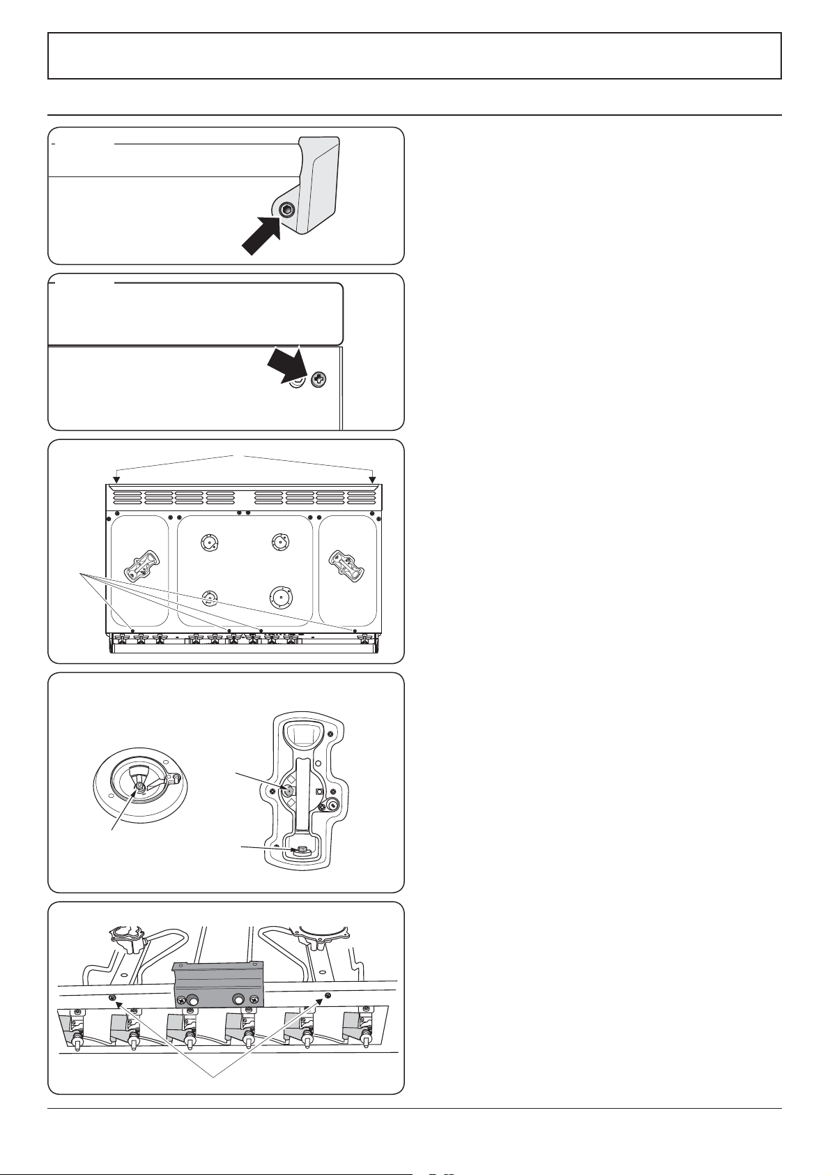
1 Panels & Handrails
1.1 To Remove the Handrail
Remove the plastic blanking plugs (Fig. 10.1) and remove the 2 end
bracket xing screws.
1.2 To Remove the Control Panel
DISCONNECT FROM THE ELECTRICITY SUPPLY.
Pull o all the control knobs. Remove the handrail (see 1.1). Remove
the 2 cross-headed screws that were hidden by the handrail end
brackets.
Open the grill door and right-hand oven door and remove the 2
screws underneath the control panel (Fig. 10.2).
Pull the control panel forward and support it so that the wires are
not strained.
Reassemble in reverse order. When replacing leads, refer to the
wiring diagram.
Check the operation of the timer, ignition, and oven light switches.
1.3 To Remove a Side Panel
DISCONNECT FROM THE ELECTRICITY SUPPLY.
Remove the control panel (see 1.2). Pull the cooker forward. Remove
the 4 retaining screws from each panel (2 at the front and 2 at the
rear). The lower front retaining screws (1 each side) are situated
beneath the lower edge at the front corners of the side panels
Reassemble in reverse order.
2 Hotplate
2.1 To Remove the Hotplate Top
DISCONNECT FROM THE ELECTRICITY SUPPLY.
Remove the pan supports, hotplate burner caps and tops. Remove
the screws holding the hotplate burners to the hotplate (but not the
spark electrode xing screws).
Remove the 2 rear hotplate xing screws ‘B’ on the cooker back
under the ue grille, and the 4 front hotplate xing screws ‘A’,
(Fig. 10.3).
Remove the screws holding the ue grille stays.
Lift the hotplate clear of the appliance.
ArtNo.210-0009 - Classic
removing the handles
A
B
C
ArtNo.311-0010 n e tors
A – Jet, B – Internal injector, C – External injector
Wok burner (some
models only)
Standard burner
A
Fig. 10.1
Fig. 10.2
Fig. 10.3
Fig. 10.4
Fig. 10.5
Loading ...
Loading ...
Loading ...