Loading ...
Loading ...
Loading ...
electrical connections
ALTER -FHE GROUNDING PRONG IN ANY
MANNER. Use an adapter as shown and always connect
the grounding lug to known ground.
It it recommended that you have a qualified electrician
replace the TWO prong outlet with a properly grounded
THREE prong outlet.
An adapter as shown below is available for connecting
plugs to 2 prong receptacles. The green grounding lug
extending from the adapter must be connected to a
permanent ground such as to a properly grounded
outlet box. ":_ROU_DI_G LtJ(_
I
A_APTE_ / r==_
\ t I: ll R,
3-PROb,h \1;_ 7 _ I ._ " I CON_ECT D TO A
PLLJG \ t'_'i/_'_+ _ II Yb40,'¢N GPOtlN)
/X'73:7":'-!I_'*: --"_'_ _ ERON--
NOTE: The adapter illustrated is for use only if you
already have a properly grounded 2-prong receptacle.
ELECTRICAL CONNECTIONS
WARNING: CHANGES IN ELECTRICAL
CONNECTIONS SHOULD BE MADE BY A
QUALIFIED ELECTRICIAN.
1, Changing Motor Connections
a. Under normal home workshop usage, and if proper
{full) voltage is supplied to the motor, your saw will
operate efficiently on 120V, as connected at the
factory However, ifanyofthe following conditions
exists, pt will be advisable for you to reconnect the
motor for 240V operation - to obtain the
efficiency and performance for which your saw is
designed:
(1) Heavy-duty operations.
(2) Either an undersized or an overloaded branch
circuit serving the saw motor.
(3) Low voltage supplied by the power source,
which the power company cannot correct.
b. Motor 'wiring connections for 120V (as made at the
factory) are described below. Necessary
reconnections for 240V operation are also described
following. Whenever changing connections from
120V to 240V or vice-versa, make certain that all
necessary steps (including proper fusing of the
branch circuit) are completed.
,f i _".... x
/ ,i ,
/ , L _'\
/ i __ _
/ \J
, _ _ _ i 1
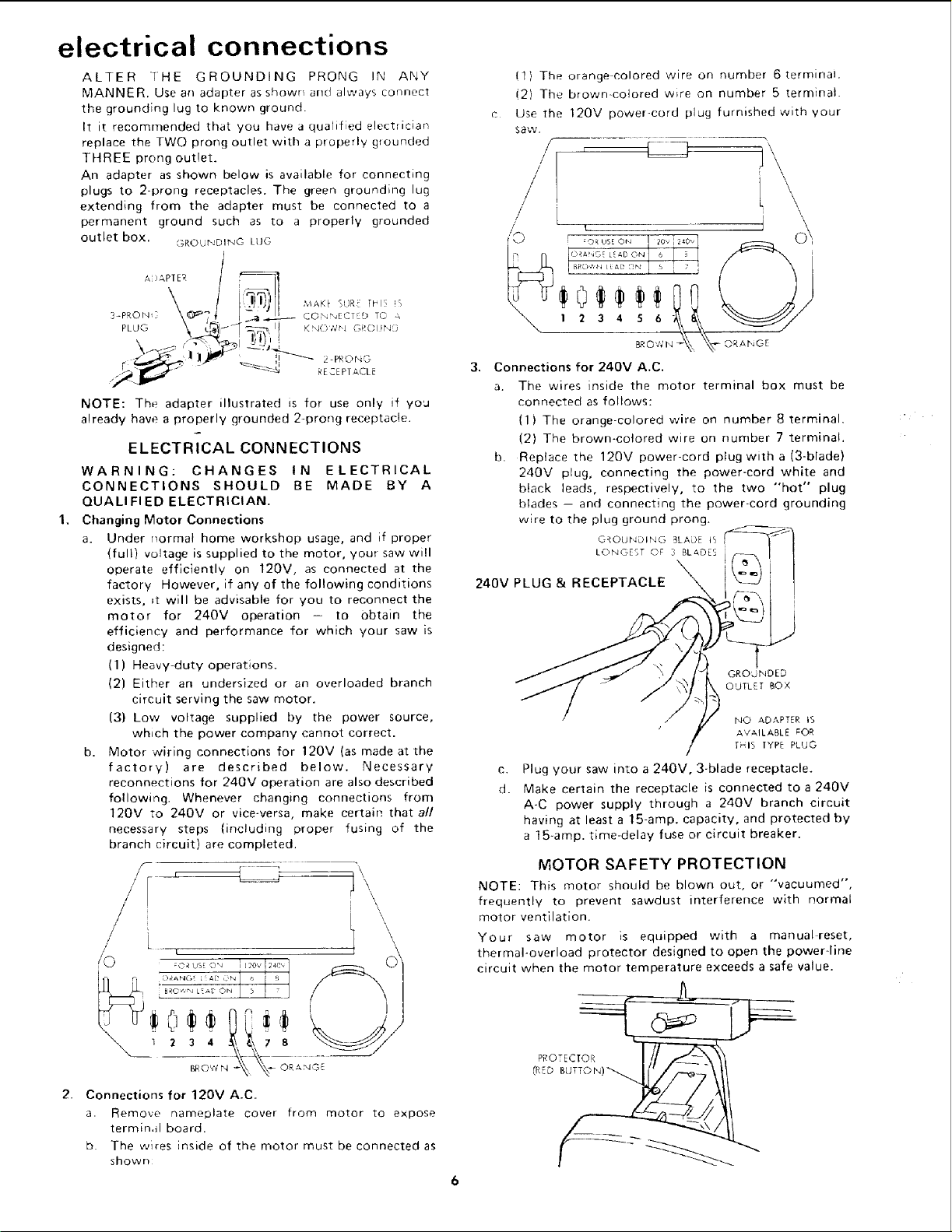
2. Connections for 1207 A.C.
a. Remove nameplate cover from motor to expose
terminal board.
b. The w_res inside of the motor must be connected as
shown
(1) The orange-colored wire on number 6 terminal.
(2) The brown-colored w_re on number 5 terminal.
c Use the 120V power-cord plug furnished with your
saw.
/' ["
/ : \
Connections for 2407 A.C.
a. The wires inside the motor terminal box must be
connected as follows:
(1) The orange colored wire on number 8 terminal.
(2) The brown-colored wire on number 7 terminal,
b. Replace the 120V power-cord plug with a (3-blade)
240V plug, connecting the power-cord white and
black leads, respectively, to the two "hot" plug
blades -- and connecting the power-cord grounding
wire to the plug ground prong,
O_OUtqDING BLADE tq, I
LONGEST OF 3 BLADE5
240V PLUG & RECEPTACLE
GROdNDED
OUTLET BOX
NO ADAPTER IS
AVAILABLE _OR
fmlb TYPE PLUG
C.
d.
Plug your saw into a 240V, 3-blade receptacle.
Make certain the receptacle is connected to a 240V
A-C power supply through a 240V branch circuit
having at least a 15-amp. capacity, and protected by
a 15-amp. time-delay fuse or circuit breaker.
MOTOR SAFETY PROTECTION
NOTE: This motor should be blown out, or "'vacuumed",
frequently to prevent sawdust interference with normal
motor ventilation.
Your saw motor is equipped with a manual reset,
thermal-overload protector designed to open the power-line
circuit when the motor temperature exceeds a safe value.
PROTECT_
Loading ...
Loading ...
Loading ...