Loading ...
Loading ...
Loading ...
adjustments to compensate for wear
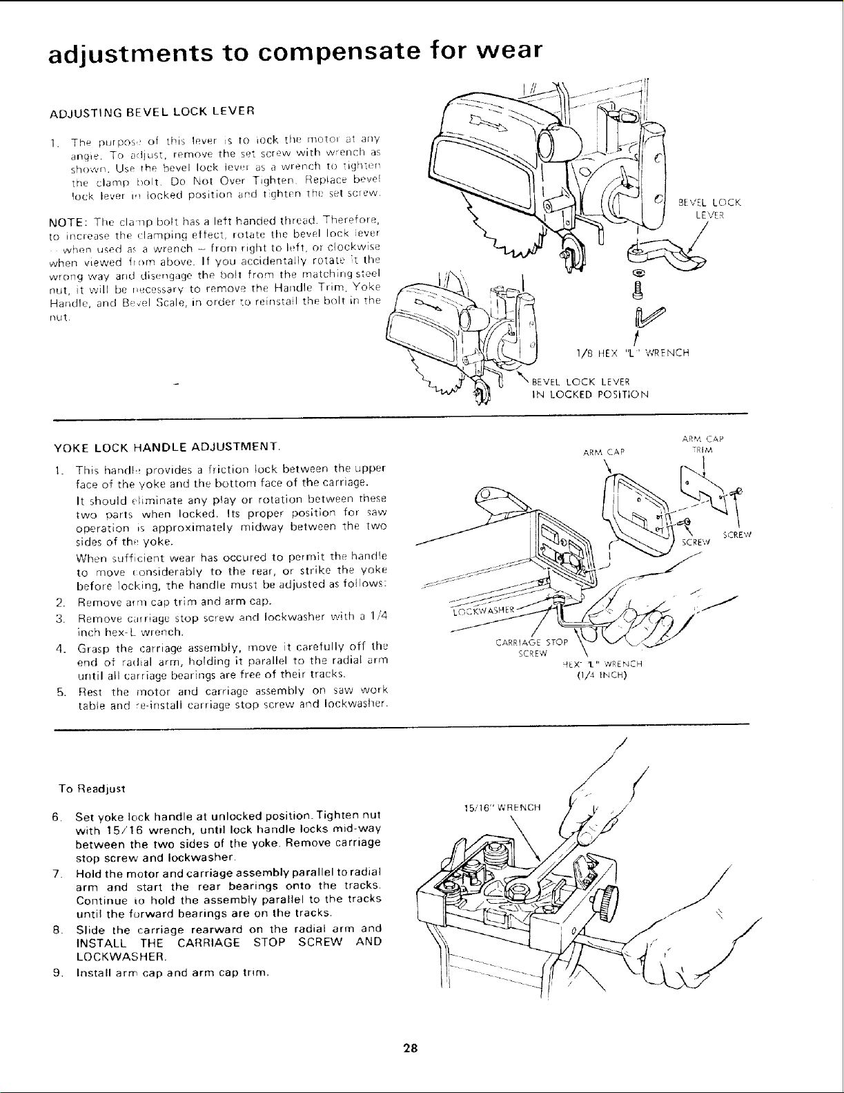
ADJUSTING BEVEL LOCK LEVER
1.
The purpos of tt_is lever _s to iock the moto_ at any
anc]ie, lo adjust, remove the set screw with wrench as
shown. Use the bevel lock tev.r as a wlendq to ight(n
the clamp i_oh Do Not Over Tighten Replace, bevel
lock lever m tocked position and t ghten the set screw
NOTE: The clamp bolt has a left handed thread. Therefore,
to increase the clamping effect, rotate the bevel lock ever
when used as a wrench - from right to left, or clockwise
when viewed horn above. If Vou accidentally rotate t the
wrong way arid disengage the bolt from the matchirlgsteel
nLit, it will be t, _eessarv to remove the Handle Trim, Yoke
Handle, and Bevel Scale, in order ;.o reinstail the bolt in the
filet.
BEVEL LOCK
LEVER
f
1/8 itEX "L' WRENCH
LOCK LEVER
IN LOCKED POSITION
YOKE LOCK HANDLE ADJUSTMENT.
1. This handh_ provides a friction lock between the upper
face of the yoke and the bottom face of the carriage.
It should eliminate any play or rotation between these
two parts when locked. Its proper position for _aw
operation _s approximately midway between the two
sides of the yoke.
When sufficient wear has occured to permit the handle
to move considerabl V to the rear, or strike the yoke
befole locking, the handle must be adiusted as foJlows:
2. Remove arm cap trim and arm cap.
3. Remove cwriage stop screw and Iockwasher with a 1/4
inch hex-L wrench.
4. Grasp the carriage assembly, move it carefully off the
end of radial arm, holding it parallel to the radial arm
until all carriage bearings are free of their tracks.
5. Rest the motor and carriage assembly on saw work
table and re-install carriage stop screw and Iockwasher.
LOC
ARM CAP
\
AR#7, CAP
TRIM
SCREW
SCREW
To Readjust
6. Set yoke lock handle at unlocked position. Tighten nut
with 15/16 wrench, until lock handle locks mid-way
between the two sides of the yoke. Remove carriage
stop screw and Iockwasher.
7. Hold the motor and carriage assembly parallel to radial
arm and start the rear bearings onto the tracks,
Continue io hold the assembly parallel to the tracks
until the forward bearings are on the tracks.
8. Slide the carriage rearward on the radial arm and
INSTALL THE CARRIAGE STOP SCREW AND
LOCKWASHER
9, Install arm cap and arm cap tnrn.
15,, 16" WRENCH
/
/
//
28
Loading ...
Loading ...
Loading ...