Loading ...
Loading ...
Loading ...
3. To cotrec_ "heel" cflndit_on proceed as follows:
a. Remove left hand carriage cover.
b. Loos_n the yoke lock handle.
c, Loosen (slightly) the t_'Jo hex-head screws.
d. Rotate the yoke assembly until gap between the
saw bade and square is eliminated.
e. Lock yoke lock handle and retighten the two hex-
head screws.
f. Recheck for "heel" and install carriage cover.
g. Loos[,n carriage lock knob.
NOTE: Tbs alignment procedure will simultaneously set
both yoke indexing positions for blade in and out rip.
HIx tE,\D 5CR[vVS
LEFT SIDE C'F ICA_RIAC2[
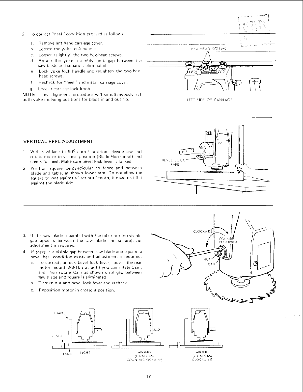
VERTICAL HEEL -ADJUSTMENT
1. With smt,,blade in 90 ° cutoff position, elevate saw and
rotate motor to vertical position (Blade Horizontal) and
check fol heel. Make sure bevel lock lever is locked.
2. Position square perpendicular to fence and between
blade and table, as shown lower arm. Do not allow the
square to rest against a "set-out" tooth, it must rest flat
against the blade side.
If the saw blade is parallel with the table top (no visible
gap appears between the saw blade and square), no
adjustment is required.
If there i,_ a visibie gap between saw blade and square, a
bevel heel condition exists and adjustment _s required.
a. To correct, unlock bevel lock lever, loosen the rear
motor mount 3/8-16 nut until you can rotate Cam,
and _hen rotate Cam as shown until gap between
saw, blade and square is eliminated.
b. Tighten nut and bevel lock lever and recheck.
c. Reposition motor in crosscut position.
\
SOUAR_\
TABLE RIGHT
'J
WRONG
(ILJRt_ C&M
C() L,INTER CL ()CK t_'lS_}
VlR0 N G
{TURN CAM
CLOCK'HISE)
1
1
17
Loading ...
Loading ...
Loading ...