Loading ...
Loading ...
Loading ...
Fs F_s _ ;ed
.
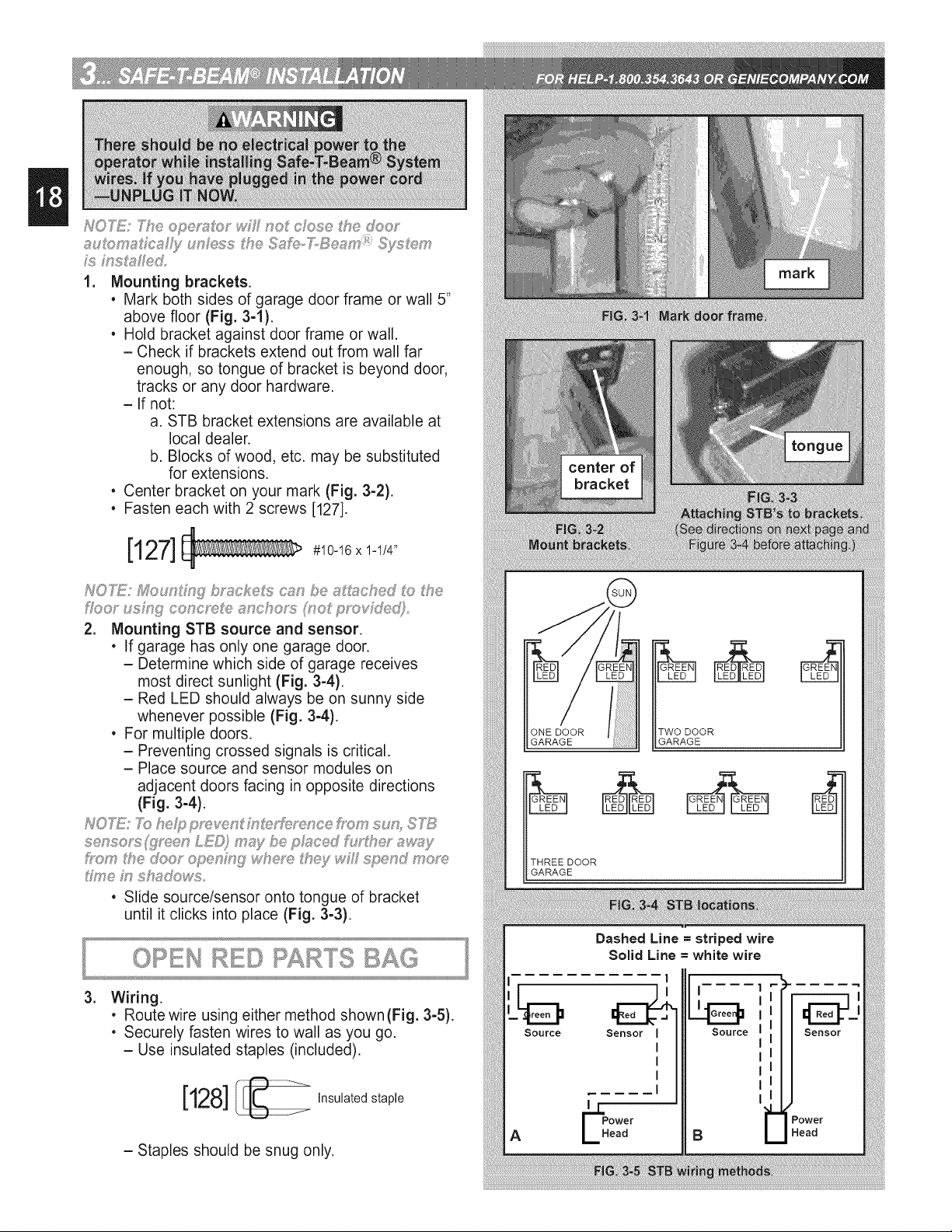
Mounting brackets.
• Mark both sides of garage door frame or wall 5"
above floor (Fig. 3-1).
• Hold bracket against door frame or wall.
- Check if brackets extend out from wall far
enough, so tongue of bracket is beyond door,
tracks or any door hardware.
- If not:
a. STB bracket extensions are available at
local dealer.
b. Blocks of wood, etc. may be substituted
for extensions.
• Center bracket on your mark (Fig. 3-2).
• Fasten each with 2 screws [127].
[127] #10-16xi-1/4,,
2, Mounting STB source and sensor.
• If garage has only one garage door.
- Determine which side of garage receives
most direct sunlight (Fig. 3-4).
- Red LED should always be on sunny side
whenever possible (Fig. 3-4).
• For multiple doors.
- Preventing crossed signals is critical.
- Place source and sensor modules on
adjacent doors facing in opposite directions
(Fig. 3-4).
• Slide source/sensor onto tongue of bracket
until it clicks into place (Fig. 3°3).
,
Wiring.
• Routewire using either method shown(Fig. 3-5).
• Securely fasten wires to wall as you go.
- Use insulated staples (included).
[128] Insulated staple
- Staples should be snug only.
ONE DOOR
GARAGE
TWO DOOR
GARAGE
THREEDOOR
GARAGE
Dashed Line = striped wire
Solid Line = white wire
Source
A
1
I
Power
Head
I i.
Source
Power
Head
Loading ...
Loading ...
Loading ...