Loading ...
Loading ...
Loading ...
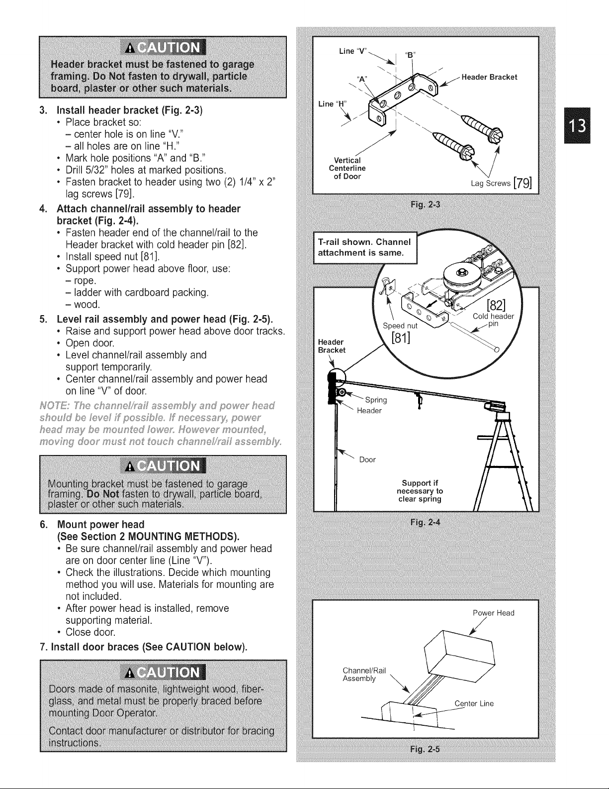
3. install header bracket (Fig. 2-3)
• Place bracket so:
- center hole is on line "V."
- all holes are on line "H."
• Mark hole positions "A" and "B."
• Drill 5/32" holes at marked positions.
• Fasten bracket to header using two (2) 1/4" x 2"
lag screws [79].
4. Attach channel/rail assembly to header
bracket (Fig. 2-4).
• Fasten header end of the channel/rail to the
Header bracket with cold header pin [82].
• Install speed nut [81].
• Support power head above floor, use:
- rope.
- ladder with cardboard packing.
- wood.
5. Level rail assembly and power head (Fig. 2-5).
• Raise and support power head above door tracks.
• Open door.
• Level channel/rail assembly and
support temporarily.
• Center channel/rail assembly and power head
on line "V" of door.
should be h_ve ff pess£_Fe ff necessuy, po_<_,r
head may be moun_,d fo_,r: _,,fo'_:_,yermouni',ed,
mevi_ £ doer must no _'ouc_ c_ anne_'_/ assembJy_
6. Mount power head
(See Section 2 MOUNTING METHODS).
• Be sure channel/rail assembly and power head
are on door center line (Line "V').
• Check the illustrations. Decide which mounting
method you will use. Materials for mounting are
not included.
• After power head is installed, remove
supporting material.
• Close door.
7. Install door braces (See CAUTION below).
T-rail shown. Channel
attachment is same.
Header
Bracket
Speed nut
[81]
Cold header
Header
Door
Supportif
yto
clearsprmg
Power Head
Channel/Rail
Assembly
\
Center Line
Loading ...
Loading ...
Loading ...