Loading ...
Loading ...
Loading ...
Read these instructions completely
before you attempt to assemble or
operate your new equipment. Your
tiller has been assembled at the fac-
tory with the exception of those parts
left unassembled for shipping pur-
poses. Steps in this section show
you how to do so. To ensure safe
and proper operation of your ma-
chine, all parts and hardware you in-
stall or adjust must be tightened se-
curely. Use the correct tools as nec-
essary to ensure proper tightness.
UNPACKINGINSTRUCTIONS
• Inspect your machine immediately.
Be sure neither the carton nor con-
tents have been damaged. If you
find or have reason to suspect
damage, contact the nearest
Sears Service Center/Department
for assistance.
• Once the cardboard shipping car-
ton is open, remove any packing
material from around the machine.
Remove any staples securing bot-
tom of carton to wood pallet. Lift
off carton. Before disposing of the
carton or any of the packing mate-
rials, be sure to check them thor-
oughly for any small parts.
• Leave unit on base of pallet dur-
.ing assembly steps (to safely re-
move unit from pallet, wait until
you have installed the handlebar
assembly).
• Also remove any packaging around
the handlebar.
• Perform the assembly on a clean,
level surface. If you need to move
the machine, be careful not to
severely bend any of the control
cables on the equipment.
Tools Needed For Assembly:
• Open,end or adjustable wrenches:
One 3/8";Two 7/16";
One 1/2"; Two9/16"
• Funnel (toadd motor oil)
• Rag (forany oil cleanup needed)
• Block of Wood (to support Me tiller
when removing wheel)
• Ruler (for belttension check)
ASSEMBLY
H
G
B
D
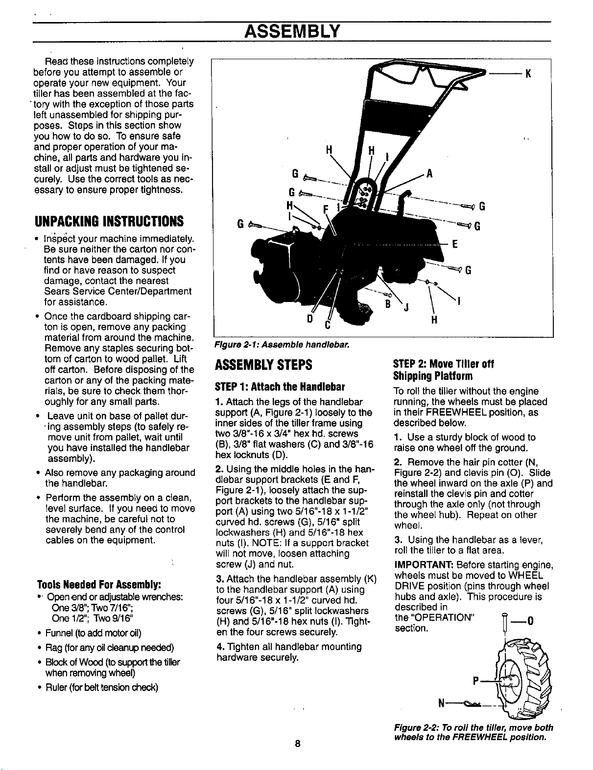
Figure 2-1: Assemble handlebar.
ASSEMBLYSTEPS
STEP1: Attach the Handlebar
1. Attach the legs of the handlebar
support (A, Figure 2-1) loosely to the
inner sides of the tiller frame using
two 3/8"-16 x 3/4" hex hd. screws
(B), 3/8" flat washers (C) and 3/8"-16
hex Iocknuts (D).
2. Using the middle holes in the han-
dlebar support brackets (E and F,
Figure 2-1), loosely attach the sup-
port brackets to the handlebar sup-
port (A) using two 5/16"-18 x 1-1/2"
curved hd. screws (G), 5/16" split
Iockwashers (H) and 5/16"-18 hex
nuts (I). NOTE: If a support bracket
will not move, loosen attaching
screw (J) and nut.
3. Attach the handlebar assembly (K)
to the handlebar support (A) using
four 5/16"-18 x 1-1/2" curved hd.
screws (G), 5/16" split Iockwashers
(H) and 5/16"-18 hex nuts (I). Tight-
en the four screws securely.
4. Tighten all handlebar mounting
hardware securely.
8
STEP2: MoveTiller off
ShippingPlatform
To roll the tiller without the engine
running, the wheels must be placed
in their FREEWHEEL position, as
described below.
1. Use a sturdy block of wood to
raise one wheel off the ground.
2. Remove the hair pin cotter (N,
Figure 2-2) and clevis pin (O). Slide
the wheel inward on the axle (P) and
reinstall the clevis pin and cotter
through the axle only (not through
the wheel hub). Repeat on other
wheel.
3. Using the handlebar as a lever,
roll the tiller to a flat area.
IMPORTANT: Before starting engine,
wheels must be moved to WHEEL
DRIVE position (pins through wheel
hubs and axle). This procedure is
described in
the "OPERATION" _ --0
section.
U
I
N ,
Figure22: Toroll the tiller,move both
wheels to theFREEWHEEL position.
Loading ...
Loading ...
Loading ...