Loading ...
Loading ...
Loading ...
Model 1! 3221611 Table Saw with Table Extensions
is shipped complete in one carton
Separate all parts from packing materials and check
each one with the illustration and the list of Loose
Parts to make certain alf items are accounted for,
before discarding any packing material
If any parts are missing, do not attempt to assemble
the table saw, plug in the power cord or turn the
switch on until the missing parts are obtained and
are installed correctly
Apioly a coat of automobile wax to the table.
Wipe att parts thoroughly with a clean, dry cloth.
WARNING: FOR YOUR OWN SAFETY, NEVER
CONNECT PLUG TO POWER SOURCE OUTLET
UNTIL ALL ASSEMBLY STEPS ARE COMPLETE,
AND YOU HAVE READ AND UNDERSTAND THE
SAFETY AND OPERATIONAl, INSTRUCTIONS_
ITEM
A
B
C
D
E
F
G
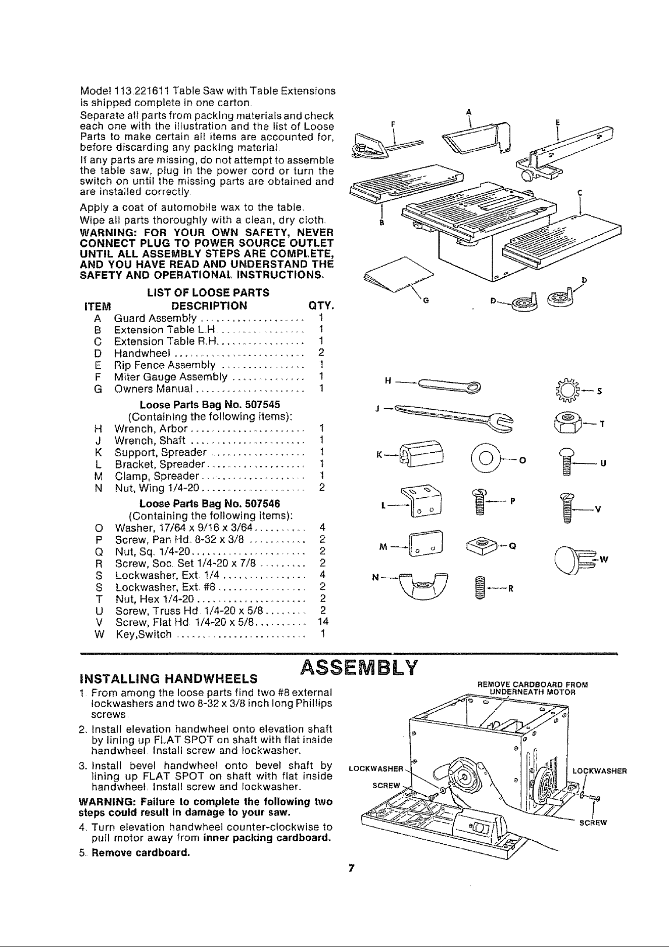
LIST OF LOOSE PARTS
DESCRIPTION QTY.
Guard Assembly ....................... 1
Extension Table LH ...................... 1
Extension Table R..H................... 1
Handwheel .............................. 2
Rip Fence Assembly ................... 1
Miter Gauge Assembly ................. 1
Owners Manual ...................... 1
Loose Parts Bag No. 507545
(Containing the following items):
H Wrench, Arbor .......................... 1
J Wrench, Shaft .......................... 1
K Support, Spreader ..................... 1
L Bracket, Spreader ..................... 1
M Clamp, Spreader_.. .................. t
N Nut, Wing 1/4-20 ....................... 2
Loose Parts Bag No. 507546
(Containing the following items):
O Washer, t7/64 x 9/16 x 3/64 .......... 4
P Screw, Pan Hd. 8_32 x 3/8 ............ 2
Q Nut, Sq.. 1/4-20 ........................ 2
R Screw, Soc. Set 1/4-20 x 7/8 ......... 2
S Lockwasher, Ext. I/4 ................ 4
S Lockwasher, Ext. #8 ...................... 2
T Nut, Hex 1/4-20 ........................ 2
U Screw, Truss Hd 1/4-20 x 5/8 ......... 2
V Screw, Flat Hd 1/4-20 x 5/8 ............ 14
W Key,Switch ........................... 1
F
D
--- o
_R
_S
INSTALLING HANDWHEELS
1 From among the loose parts find two #8 external
tockwashers and two 8-32 x 3/8 inch long Phillips
screws
2. Install elevation handwheel onto elevation shaft
by lining up FLAT SPOT on shaft with flat inside
handwheel. Install screw and Iockwasher.
3. Install bevel handwheel onto bevel shaft by
lining up FLAT SPOT on shaft with flat inside
handwheet, Install screw and Iockwasher
WARNING: Failure to complete the following two
steps could result in damage to your saw.
4. Turn elevation handwheel counter-clockwise to
pull motor away from inner packing cardboard,
5 Remove cardboard.
ASSEMBLY
LO(
SCREW
REMOVE CARDBOARD FROM
UNDERNEATH MOTOR
LOCKWASHER
SCREW
7
Loading ...
Loading ...
Loading ...