Loading ...
Loading ...
Loading ...
64 installation
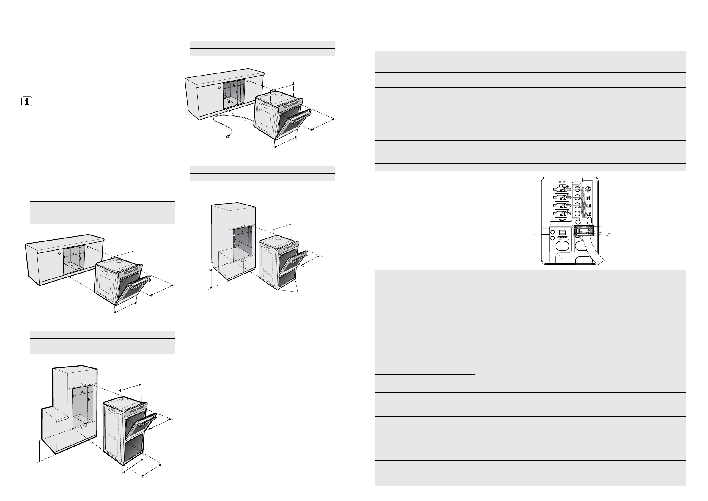
Underbench oven
Your underbench oven looks best when the control panel
is directly under the benchtop. An upper infill panel may
be added if the cooktop placed above the benchtop is too
deep. Refer to cooktop installation instructions for required
clearance between cooktop and oven.
IMPORTANT!
Note: Dimension’D’*
A requirement for all EVEPxxxx pyrolytic clean ovens and
Duo ovens – for proper ventilation there must be a gap
at the bottom rear of the cabinet. This can be a full width
opening 20mm deep.
Power point connection for the EVEP615SB and
EVEP618BB must be accessible with the appliance fully
installed. If the supply cord is damaged it must be replaced
by the manufacturer, its service agent or similarly qualified
persons in order to avoid a hazard.
Cut-out dimensions
type of fit A (width) B (height) C (depth)
Flush fit (mm)
600 600 581 min.
Proud fit (mm) 568 590 560 min.
Double oven Cut-out dimensions
type of fit A (width) B (height) C (depth)
Flush fit (mm)
600 1086 581 min.
Proud fit (mm) 568 1078 560 min.
INSTALLATION OF THE APPLIANCE
Pyrolytic underbench cut-out dimensions
type of fit A (width) B (height) C (depth) D*
Flush fit (mm)
600 600 581 min. 20
Duo oven cut-out dimensions
type of fit A (width) B (height) C (depth) D*
Flush fit (mm)
600 893 581 min. 20
596mm
561mm
561mm
561mm
mounting
holes 582mm
mounting holes
582mm
fit long screws
provided
mounting holes
fit countersunk screws
with plastic spacers
provided
mounting
holes 582mm
596mm
650mm
min.
Plastic clips
Plastic clip
securing points
installation 65
Hard wiring details
1. Remove terminal cover plate from rear panel of
appliance.
2. Fit wires through hole in cover plate and make
connections to terminals.
3. Engage wires into plastic clip. Secure plastic clip with
two long silver screws (supplied in separate bag).
4. Replace cover plate onto rear panel.
Error codes
TECHNICAL SPECIFICATIONS
model
product dimensions
(h x w x d) mm
electrical
connection
min. fuse rating max. power rating max. current rating
EVE611SA 597 x 596 x 573 230-240V/50Hz 16A 3.1kW 12.9A
EVE613SA 597 x 596 x 573 230-240V/50Hz 16A 3.1kW 12.9A
EVE614BA 597 x 596 x 573 230-240V/50Hz 16A 3.1kW 12.9A
EVE616BA 597 x 596 x 573 230-240V/50Hz 16A 3.1kW 12.9A
EVEP611SB 597 x 596 x 573 230-240V/50Hz 16A 3.1kW 12.9A
EVEP614BB 597 x 596 x 573 230-240V/50Hz 16A 3.1kW 12.9A
EVEP613SB 597 x 596 x 573 230-240V/50Hz 16A 3.1kW 12.9A
EVEP616BB 597 x 596 x 573 230-240V/50Hz 16A 3.1kW 12.9A
EVEP615SB 597 x 596 x 573 230-240V/50Hz 16A 3.5kW 12.9A
EVEP618BB 597 x 596 x 573 230-240V/50Hz 16A 3.5kW 12.9A
EVE623SA 890 x 596 x 573 230-240V/50Hz 25A 5.3kW 22.1A
EVEP623SB 890 x 596 x 573 230-240V/50Hz
25A 5.3kW 22.1A
EVEP626BB 890 x 596 x 573 230-240V/50Hz
25A 5.3kW 22.1A
EVE633SA 1083 x 596 x 573 230-240V/50Hz
25A 6.2kW 24.2A
error code description comment fix
F01 or 01 Door lock sensor alarm
This relates to a door lock failure which is only
associated with the Pyrolytic product
Check wiring/plugs or replace door lock
F02 or 02 Door lock actuator alarm
F04 or 04 Oven Probe (PT500) out
This relates to the temperature sensing probe
which may be out of tolerance, of range alarm
or have open/short circuit connections
Replace probe
F05 or 05
Oven Probe (PT500) too
high temperature alarm
25
Board Temperature
Sensor (NTC) too high
temperature alarm
This relates to the temperature of the
powerboard and/or the (NTC)
on the powerboard
Cooling fan not working or replace
powerboard
26
Board Temperature
Sensor (NTC) out of
range warning
6
Board Temperature
Sensor (NTC) out of
range alarm
F08 or 08 Communication alarm
This relates to an error in communication
between the powerboard and the IOI
controller. This can occur if the IOI controller is
connected while the powerboard is energised
Reset power. (Minimum of 20 sec.) or
check or replace data cable
F09 or 09
Software compatibility
code alarm
This relates to a mismatch between
powerboard firmware version and the IOI
controller firmware version. Most likely caused
by an un-programmed powerboard
Replace Powerboard
C1 Telescopic runners fitted Only applies to Pyrolytic product
Remove both side racks and re-start
pyrolytic cycle
C3 Door open Only applies to Pyrolytic product Close door and restart pyrolytic cycle
F03 or 03
EEPROM check sum
alarm
Relates to the controller Replace Controller
F14 or 14
EEPROM compatibility
code alarm
Relates to the controller Replace Controller
D
561mm
650mm
min.
596mm
mounting
holes 582mm
mounting
holes 582mm
Loading ...
Loading ...